SPEAKER DISTRIBUTION SYSTEM OWNERS MANUAL ®
Introduction 3 DS70 Features 3 Guided Tour 4 Modes of Operation 5 Wiring Diagrams 6 Four-Zone 70V (Unbridged) 6 Two-Zone 70V (Bridged) 7 Four-Zone 25.
Introduction / DS70 Features Congratulations on purchasing the Samson DS70 Speaker Distribution System! The DS70 provides four high-quality toroidal step-up transformers in a single chassis. Each transformer can accept a nominal-level signal from any standard power amplifier, and can then convert it to a 70 volt, 25.2 volt, or 100 volt line-level output for use in paging and public address systems and wherever long cable runs and multiple speakers are required.
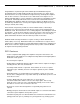
Guided Tour 4 X 120WATT 120W TT 70 VOL OLT T SPEAKER DISTRIBUTION DISTRIBUTION SYSTEM DS70 + RISK OF ELECTRIC SHOCK DO NOT OPEN 70V 25.2V COM COM – INPUT + – + – INPUT – + AVIS DS70 CAUTION RISQUE DE CHOC ELECTRONIQUE NE PAS OUVRIR DO NOT EXPOSE THIS EQUIPMENT TO RAIN OR MOISTURE SPEAKER DISTRIBUTION BRIDGE 70V 70V 25.2V COM CH1 COM CH2 CH3 BRIDGE CH4 BRIDGE 70V 25.2V COM COM BRIDGE 70V 70V 25.2V COM COM SAMSON SAMSON TECHNOLOGIES CORP.
About Distributed Sound A distributed sound system (sometimes known as a “constant voltage” system) allows a single power amplifier to drive multiple loudspeakers over a single high-impedance line. Used commonly in public address and paging systems (such as in schools, houses of worship, hotels, factories, stores, and other places of business), distributed sound offers numerous advantages: • All wiring is in parallel and is therefore simple and straightforward.
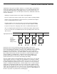
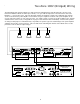
Four-Zone 70V (Unbridged) Wiring The illustration below shows the wiring for a single channel of a DS70 being used in standard 70 volt mode. In this kind of setup, the output level controls of the power amplifier can be used to control the volumes of each of the four zones. For volume control of each of the speakers within a zone, an optional autotransformer can be used (see Appendix A on page 9 of this manual for more information).
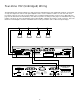
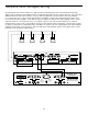
Two-Zone 70V (Bridged) Wiring The illustration below shows the wiring for two channels of a DS70 being used in Bridged 70 volt mode. Since the two input channels are bridged, a signal of up to 240 watts (into 8 ohms) can be received from the power amplifier. In this kind of setup, the output level controls of the power amplifier can be used to control the volumes of each of the two zones.
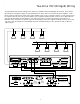
Four-Zone 25.2V (Unbridged) Wiring The illustration below shows the wiring for a single channel of a DS70 being used in 25.2 volt mode. In this kind of setup, the output level controls of the power amplifier can be used to control the volumes of each of the four zones. For volume control of each of the speakers within a zone, optional autotransformers can be used (see Appendix A on page 9 of this manual for more information).
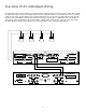
Two-Zone 100V (Bridged) Wiring The illustration below shows the wiring for a single channel of a DS70 being used in 100 volt mode. Because each transformer within the DS70 can deliver up to 70 volts, so to get a 100 volt output, two of the transformers have to be bridged (i.e., connected in series). Since the two input channels are bridged, a signal of up to 240 watts (into 8 ohms) can be received from the power amplifier.
Two-Zone 140V (Bridged) Wiring The illustration below shows the wiring for a single channel of a DS70 being used in a non-standard 140 volt mode (which can be used with custom equipment where exceptionally long cable runs are required. Because each transformer within the DS70 can deliver up to 70 volts, so to get a 140 volt output, two of the transformers have to be bridged (i.e., connected in series).
Appendix A: Block Diagram Note: The block diagram below shows the signal flow for a single channel of the DS70.
Specifications 4 Ω (non-bridged modes) 8 Ω (bridged modes) 2 Ω (dual mode) 1: Input Impedance 2: Maximum Power Each Input 120 Wrms (non-bridged modes) 240 Wrms (bridged and dual modes) 3: Output 70 V, 25.2 V (non-bridged), 100 V, 140 V (bridged) 4: Insertion Loss -0.55 dB @ 1kHz 5: Frequency Response Flat, +0 dB, -3 dB 20 Hz to 20 kHz, ref. 1 kHz -1 dB, 15 Hz & 9.1 kHz @ 120 Wrms -3 dB, 10 Hz & 20 kHz @ 120 Wrms 6: THD + N < .04% @ 120 Wrms 7: Dimensions 482 mm (w) x 190 (d) x 88 (h) 19 in.
Produced by On The Right Wavelength for Samson Technologies Corp. Copyright 1998, Samson Technologies Corp. Printed January 1998 Samson Technologies Corp. 575 Underhill Blvd. P.O.