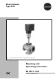
Electric Actuator Type 3374 Fig.
Contents Contents Page 1 1.1 1.2 Design and principle of operation . . . . . . . . . . . . . . . . . . . 5 Additional equipment. . . . . . . . . . . . . . . . . . . . . . . . . . 5 Technical data . . . . . . . . . . . . . . . . . . . . . . . . . . . . . 6 2 2.1 2.2 Installation . . . . . . . . . . . . . . . . . . . . . . . . . . . . . . . 8 Mounting position . . . . . . . . . . . . . . . . . . . . . . . . . . . 8 Attachment to the valve . . . . . . . . . . . . . . . . . . . . . . . . .
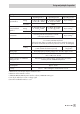
Safety instructions General safety instructions 4 Assembly, start-up and operation of this device may only be performed by 4 4 4 trained and experienced personnel familiar with the product. According to these mounting and operating instructions, trained personnel refers to individuals who are able to judge the work they are assigned to and recognize possible hazards due to their specialized training, their knowledge and experience as well as their knowledge of the applicable standards.
Note: Actuators with a CE marking fulfill the requirements of the Directives 94/9/EC and 89/336/EEC. The Declaration of Conformity is available on request.
Design and principle of operation 1 Design and principle of operation The Type 3374 Electric Actuator is used in industrial plants as well as in heating, ventilation and air-conditioning systems. The linear actuator is suitable for form-fit attachment to various SAMSON valve series, depending on the version with or without fail-safe action. The actuators consist of a reversible synchronous motor and a maintenance-free planetary gear with ball screw.
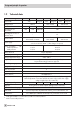
Design and principle of operation 1.2 Technical data Actuator Type 3374 -10 Version with -11 Yoke Safety function Rated travel -21 -26 -31 -36 Yoke Ring nut Yoke Ring nut Without mm Actuating time for rated travel s Actuating time in case of fail-safe action s Stem extends Stem retracts 30 15 30/15 15 240 120 240/120 120 – 12 2.5 kN Stem extends or retracts Nominal thrust 2 kN Stem extends 0.5 kN Stem retracts 207 V to 253 V; 50 Hz, 90 V to 127 V; 60 Hz or 21.6 V to 27.
Design and principle of operation Digital positioner 1) Input variable 2) Range Operating mode 1 Operating mode 2 Operating mode 3 4...20 mA, Ri = 0.05 kΩ 2...10 V, Ri = 10 kΩ 0...20 mA, Ri = 0.05 kΩ 0...10 V, Ri = 10 kΩ As per settings 3) Resolution Position feedback signal 4) 5) Range 4...20 mA, RB 0.2 ≤ kΩ 2...10 V, RB ≥ 5 kΩ Resolution 0...20 mA, RB ≤ 0.2 kΩ 0...
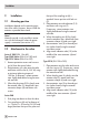
Installation 2 Installation 2.1 Mounting position Installation depends on the mounting position of the valve. However, do not install the actuator suspended downwards. Note! Manual override is only possible in actuators with fail-safe action when the power supply is connected (see section 4.1). 2.2 Attachment to the valve Series V 2001 (DN 15 to 80), Type 3260 Valves (DN 65 to 150) and Type 3214 Valves (DN 65 to 100) 1. Remove protective covers and unscrew nut (6) from the control valve. 2.
Installation Attachment to Series V 2001, Type 3260 DN 65 to 150 and Type 3214 DN 65 to 100 Attachment to Series 240 1 1 2.1 2.3 7 x 3 3 4 8 9 4 5 6 10 5 1 2.2 7 3 10 4 5 Attachment to Type 3214 DN 125 to 250 1 2.1 Actuator Actuator yoke 2.2 2.3 3 4 5 6 7 8 9 10 Valve yoke Bonnet Actuator stem Stem connector Plug stem Nut Ring nut Coupling nut Lock nut Travel indicator scale Fig.
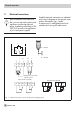
Electrical connections 3 Electrical connections Upon installation of the electric cables, you are required to observe the regulations concerning electrical power installations according to DIN VDE 0100 as well as the regulations of your local power supplier. Establish electrical connections as indicated on the circuit diagram on the actuator cover and as illustrated in Figs. 3 and 4. A maximum of 3 cable glands can be attached to the housing for cable entries.
Electrical connections Caution! 4 Only connect to the main power network 4 Particularly for 24 V, 50 Hz actuators, when the power is switched off. use wires with a sufficiently large cross-section to guarantee that the per4 Only use power interruption devices which ensure that the power cannot be switched on again unintentionally. missible voltage tolerances are not exceeded. Limit switches (optional) 41 44 42 51 54 52 Load, max.
Operation and setting 4 Operation and setting 4.2.1 Limit switches 4.1 Manual operation of the actuator 1. Use motor or manual override to move the control valve to the position where the switching function is to be activated. 2. Use hex wrench to turn spindle (2) for the upper limit switch or spindle (3) for the lower limit switch until the associated contact cam on the cam bracket (7) triggers the switch contact of the upper or lower microswitch (1).
Operation and setting Limit switch Stem retracts Metal tag Stem extends Rated travel inscription 12 12.1 e 13.1 a N B en n 15 hu b a 13 1 2 3 5 7 12 12.1 13 13.1 1 2 3 7 Microswitch Spindle upwards Spindle downwards Intermediate gear Cam bracket Gear potentiometer 1 Potentiometer shaft Gear potentiometer 2 Potentiometer shaft 5 Fig.
Operation and setting 4.3 Setting the digital positioner In the actuator version with digital positioner, the travel is calibrated automatically, allowing the travel (controlled variable x) and the input signal (reference variable w) of the positioner to be matched in the best possible way. Additionally, the digital positioner provides valve position feedback for remote transmission. Setting and start-up can be carried out using four different operating modes.
Operation and setting Press the button briefly to obtain a travel calibration for valve CLOSED when the actuator stem extends. Direction of action: Increasing/increasing. Caution! The automatic travel calibration lasts approximately twice as long as the actuator's transit time. During this period, the valve leaves its current position. Calibrate the travel either on the test bench or when the shut-off valves in the plant are closed.
Operation and setting as it will go to the valve's CLOSED position. Calibration is carried out when both signal lamps (8 and 9) are lit. Travel calibration starts after the mounting position of the potentiometer gear (12) has been determined automatically. This is indicated by signal lamp (8) for 6 to 35 mm travel and by signal lamp (9) for 6 to 20 mm travel. When travel calibration starts, the lower signal lamp (9) blinks quickly for about 10 seconds.
Retrofitting additional electrical equipment Setting with limited travel range Travel calibration is usually based on the maximum travel of the control valve. If, however, the maximum possible travel is to be limited to a smaller travel end value, press the button (4) once at the start of calibration while the signal lamp blinks for 10 seconds. As a result, travel calibration via the potentiometer gear with rated travel 15 or 30 is limited to 6 mm.
Retrofitting additional electrical equipment 5.1 Limit switches The retrofit kit (order no. 1400-8830) is required to install limit switches. If the actuator is not already equipped with potentiometers or a positioner, the basic unit (order no. 1400-8829) is also required. The unit includes the spindle gear (2) and the intermediate gear (5). Note! To mount the limit switches, the actuator stem must be in end position, i.e. the stem must be either fully extended or fully retracted.
Retrofitting additional electrical equipment 1 Actuator board 9 Spacer 2 3 Spindle gear Sleeve 10 Serrated ring 11 4 Spindle Terminal board with microswitches 5 6 Intermediate gear Contact cam 12 Gear in version with potentiometer 7 Cam bracket 8 Adjustment gear 7.1 Position of the contact cams (6) on the cam bracket (7) 8 9 5 4 3 2 1 7 12 6 6 For actuator stem retracts extends 7.
Retrofitting additional electrical equipment 5.2 Potentiometers Actuators with a digital positioner cannot be equipped with potentiometers. To install the potentiometers, an actuator board with the appropriate potentiometers and gears (12 and 13) is required. If the actuator is not already equipped with limit switches, the basic unit (order no. 1400-8829) is also required. The unit includes the spindle gear (2) and the intermediate gear (5). 1. Remove the fastening screws.
Retrofitting additional electrical equipment 5.3 Digital positioner To install a positioner, a corresponding actuator board and TROVIS-VIEW 3374 and connecting cable 0450-1978 are necessary. If the actuator is not already equipped with limit switches, the basic unit (order no. 1400-8829) is also required. The unit includes the spindle gear (2) and the intermediate gear (5).
Retrofitting additional electrical equipment 5.3.1 Calibrating the positioner To calibrate the positioner, proceed as described in section 4 of EB 8331-2 EN. 5.3.2 Simplest method to calibrate the actuator If tools such as the TROVIS-VIEW software, PC etc. are not available for calibration of the actuator and the actuator operation with maximum precision is not necessary, the simplest calibration method can be performed as follows: 1. Position the selector switch (2) to operating mode 0 = . 2.
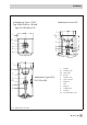
Dimensions in mm Dimensions in mm Version with yoke Version with ring nut 193 120 30 (15) Stem connector 90 (75) 15 (30) 294 204 60 50 6 EB 8331-1 EN 23
EB 8331-1 EN S/Z 2007-10 SAMSON AG · MESS- UND REGELTECHNIK Weismüllerstraße 3 · 60314 Frankfurt am Main · Germany Phone: +49 69 4009-0 · Fax: +49 69 4009-1507 Internet: http://www.samson.