Important Safety Information ATTENTION RISQUE D'ELECTROCUTION ! NE PAS OUVRIR! CAUTION: TO REDUCE THE RISK OF ELECTRIC SHOCK, DO NOT REMOVE COVER (OR BACK). NO USER-SERVICEABLE PARTS INSIDE. REFER SERVICING TO QUALIFIED SERVICE PERSONNEL. This lightning flash with arrowhead symbol within an equilateral triangle is intended to alert the user to the presence of non-insulated "dangerous voltage" within the product's enclosure that may be of sufficient magnitude to constitute a risk of electric shock.
Important Safety Information 1. Read these instructions. 2. Keep these instructions. 3. Heed all warnings. 4. Follow all instructions. 5. This apparatus shall not be exposed to dripping or splashing liquid and no object filled with liquid, such as a vase, should be placed on the apparatus. 6. Clean only with a dry cloth. 7. Do not block any of the ventilation openings. Install in accordance with the manufacturer•s instructions. 8. 9. paratus.
Table of Contents Introduction . . . . . . . . . . . . . . . . . . . . . . . . . . . . . . . . . . . . . . . . . . . . . 5 Features . . . . . . . . . . . . . . . . . . . . . . . . . . . . . . . . . . . . . . . . . . . . . . . 6 Setting Up the XP150 . . . . . . . . . . . . . . . . . . . . . . . . . . . . . . . . . . . . . . . 7 XP1 SO Quick Start . . . . . . . . . . . . . . . . . . . . . . . . . . . . . . . . . . -. . . . . . . 9 Configuring the XP1 SO for Transport . . . . . . . . . . . . . . . . . . . . .
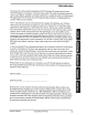
Introduction Thank you for purchasing the Expedition XP150 Portable PA System from Samson! The XP150 features a compact, 5-channel mixer with 150 watts of on board power and dual 2-way speakers, making it an ideal solution for a variety of small- to medium-size d PA applications. The XP150 is also extremely portable, thanks to its lightweight and unique "Slide and Lock" design. The 5-channel mixer can be removed from the speaker for tabletop use.
Features • The XP150 is a compact PA system with dual 2-way speakers, on board mixer, and 150 watt power amplifier. • The XP150 is the ultimate in portability . The lightweigh t, clever design allows you to slide and lock the two speakers together to carry all componen ts together in a single, easy to move case. The mixer is stored in one of the speaker cabinets. The second cabinet has a compartm ent for storing the speaker cables, microphon es, and other accessories.
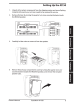
Setting Up the XP150 1. Unpack all the system components from the shipping carton and save all packing materials in the event your unit ever needs to be returned for service. 2. Remove the mixer by turning the quarter turn screw counterclockwise towards the RELEASE position. LOCK ® 111111 m~Wf.111111111 RELEASE ® ® ~ ~0 ~~· 0 111111 ifil~ 111111111 ® o: ~o~~ oEi} ~o~~ o(O ~ ~~ 00 0 3. Carefully hold the mixer to remove it from the speaker. 4.
Setting Up the XP150 5. Replace the accessory panel by aligning the bottom of the panel with the slots. Make sure the quarter turn screw is in the RELEASE position; then close the panel and turn the quarter turn screw clockwise to LOCK. 6. Position the speakers on the floor or on stands. 7. Using one of the included speaker cables, connect the mixer's LEFT SPEAKER OUT to the left speaker's input connector.
XP150 Quick Start 1. Be sure that the XP150's POWER switch is set to the OFF position. 2. If the speakers are not connected, connect the speaker wires as described in the previous section. 3. Turn each of the channel volume (VOL) and MASTER volume controls fully counterclockwise, to the "0" position. 4. Next, connect one side of the included power cable to the XP150 mixer's power inlet and the other to a grounded AC power outlet. 5.
XP150 Quick Start 8. Start talking or playing into channel1 while slowly adjusting the VOL control until you have reached the desired level. Do the same for each channel you are using. 9. If you notice that the POWER/PEAK indicator is lighting constantly, turn the MASTER volume down so that the indicator only lights occasionally. 10. To add depth to the mix or smooth out the vocals, you can apply reverb to channel 1-3.
Configuring the XP150 for Transport You can easily carry your sound system using the XP150's 1/Siide and Lock" feature. The liS Iide and Lock" speaker enclosures allow you to connect both speakers together into a single, easy to carry unit. Follow these steps to configure the XP150 for easy transport. 1. Place one speaker on the floor and · set it on its side. 2.
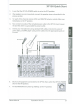
XP1 SO Mixer Layout ® ---- ® 1 ® CH'1 ® 1. XLR Mic Input Connectors (channels 1-3)- Use these XLR jacks to connect low impedance microphones to the XP150's built-in mic preamps. 2. %-inch Line Input Connectors (channels 1-3)- Use these 1.4" jacks to connect instrument or audio sources with line level signals to the XP150. You can connect the outputs from acoustic guitar pickups, keyboards, drum machines, CD/MP3 players and other units with line level outputs here. 3.
XP150 Mixer Layout 7. REVERB Switch- Use the REVERB switch to add an effect to a Mic or Line input on any of the inputs 1-3. The REVERB LED indicator lights GREEN when the REVERB is ON. 8. REVERB Indicator-The REVERB LED will illuminate when the REVERB switch is pressed down, indicating the channel is set to add reverb (see #7 above). 9. VOLUME Control Knob- This knob sets the overall level for each channel's Mic or Line input.
.,....>< .... ~ ------- U1 0 ~ -----1 f ~ ~ IRimiWimiRIIIWIIIWIIIRI!I c=::J o II ~--~ ® X ""0 m a. c=;: 6' ::::l -u ~ U1 0 ® ----- 0 0 0 - m X ---- a:------ HF D 1DK ~11, HF 10K D aQX"'"".-e aQX"'"".-s ~~~ +-11!1 ,.,a_ ~~~ +.. ,., ,,l'- 'IOtffi\10 'IOtffi\_10 o HF 10K a.f..~X"'"".-a\ 10 'IDC> .. ~ 1 ul1- · +lJ1e HF o 10K A .-.MUSIC _o 1o_ tffi\. ~~~ D 18°- 1---- . -.. " LF LF IU I I I ® VDL t ® f.~0;1(''..,...,\ ;I(..,..._ ~; \ f.
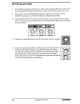
XP150 Wiring Guide There are several ways to interface the XP150 to support a variety of applications. The XP150 features balanced inputs, so connecting balanced and unbalanced signals is possible. Unbalanced Y4" Connector Tip (signal) Signal Sleeve (ground) Ground Ground Stereo TRS 3.
Specifications , Amplil1e1 · 150 W@ 80 (75 W per channel) RMS Power Frequency Response 40Hz-20kHz Power Consumption AC Input 100V--240V 50/60Hz 180W Low Frequency 6" bass transducer High Frequency 1"tweeter XLR, ~"balanced, 3.5 mm stereo Inputs 114" Speaker output Outputs + 15V DC, Fixed Phantom Voltage Phantom Power Input Channel EQ High 1OkHz Shelving ±15 dB Low 100Hz Shelving ±15 dB Speech/Music Switch Two Color LED- Power/Peak Indicators Dimensions 150Hz, 18dB/Octave Length 15.
~ m 0::: :J CD ...,_ LrJ > LrJ ..JO:O::: en s: Q) :J c: Q) -I -32dBu I + + Inputs CH1-3 ~ I HIGH LOW II OdBu - LEVEL REVERB. I I "'0 CD a. a: 0 :JI n ~ BA/ X -o ~I I EQ I I ~w ~GH ++ Inputs CH4/5 I I OdBu I LEVEL I . . . . ~ . ~ L ~- .