���������� ���� ���� ���� ��������� ���� � � ������� ��� � � �� � � ���� �� � � �� �� �� �� �� � � � ���� �� �� ������� ������ ������� ����� ����� ����� ������� �������� �� � �� �� ����� ������ �� � � � ���� � �� � ���� �� �� �� ��� �� � � � ���� � � ���� ���� �� � �� �� �� �� �� �� � � ��� �� � � ���� �� ���� �������� � �� � �� �� �� ��������� ��� � ��� �� � ��� ������� � �� � �� �� �� �� �� � ��� �� ���������
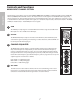
Safety Instructions/Consignes de sécurité/Sicherheitsvorkehrungen/Instrucciones de seguridad RISK OF ELECTRIC SHOCK DO NOT OPEN WARNING: To reduce the risk of fire or electric shock, do not expose this unit to rain or moisture. To reduce the hazard of electrical shock, do not remove cover or back. No user serviceable parts inside. Please refer all servicing to qualified personnel.
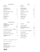
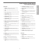
Table of Contents Inhalt Introduction 2 Einleitung 34 MDR6 Features 3 MDR6 Features 35 Controls and Functions Front and Rear Panel Layout Mono Input Channel Section MasterSection 4–5 6–7 8–9 Regler und Funktionen Vorder- und Rückseite Mono-Eingangskanal-Sektion Master-Sektion 36–37 38–39 40–41 MDR6 Input and Output Connections 10–11 MDR6 Eingänge und Ausgänge 42–43 Operating the MDR6 12–15 MDR6bedienen 44–47 System Set-ups 16–17 System-Einrichtungen 48–49 MDR6 Wiring Guide 66 MDR
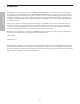
ENGLISH Introduction Congratulations on your purchase of the Samson MDR6 mixer! The MDR6 is an six channel mixer, with four low noise microphone pre-amps. The MDR6 also features HDM (Hard Disk Mode), which when engaged, provides a special monitoring and bussing mode ideal for interfacing with a computer based hard disk recorder. Clean, clear sound reproduction packaged in a rugged enclosure, ensure reliable high quality sound from performance to performance.
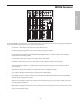
MDR6 Features ���������� ���������� ���� ���� ���� � �� � � �� � � ���� �� � � �� �� �� � � � ���� �� �� ������� ������ ������� ����� ����� ����� ������� �������� �� � �� �� ����� ������ �� � � � ���� � �� � ���� �� �� �� ��� �� � � � ���� � � ���� ���� �� � �� �� �� �� �� �� � � ��� �� � � ���� ���� �������� � �� � �� �� �� �� �� �� � � ��� �� ��������� ��� � �� � �� �� �� �� �� � ��� �� ��� ������� ��� �����
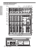
Controls and Functions Front and Rear Panel Layout 11 1 13 12 15 14 16 17 MIC/LINE 1 ENGLISH 2 MIC/LINE 2 MIC/LINE 3/4 MASTER SECTION MIC/LINE 5/6 LEFT LEFT LEFT/MONO AUX OUT 18 3 30 GAIN GAIN CLIP CLIP 4 5 +26 -26 3/L 30 5/L LINE IN AUX RET CR OUT MIX OUT RIGHT RIGHT RIGHT LINE IN MONO OUT 19 20 60 5 -26 +26 4/R 60 6/R 21 5 0 5 6 10 0 5 7 15 10 0 5 15 0 5 15 10 15 LF 0 5 15 15 0 10 10 15 LF 15 0 0 5 15 2T IN 23 2T OUT 10 1
Front and Rear Panel Layout Front and Rear Panel Layout 18 2 TRACK INPUTS & OUTPUTS – Connect a DAT, Cassette, Mini Disk or Hard Disk Recording system. FRONT PANEL MIC/LINE – Combination Input connector for Low-Noise Microphone pre-amp and Line level inputs. 2 GAIN – Used to set the input level of the mic pre and line input. 3 CLIP – Red LED will illuminate indicating when the mic GAIN has been adjusted too high. 4 HIGH FREQUENCY – Controls the high band of the Channel Equalizer, +/- 15 dB at 12KHz.
Controls and Functions ENGLISH MONO INPUT CHANNEL SECTION The following section details each part of the MDR6’s MONO INPUT CHANNELS including the GAIN control, 3-BAND EQ, AUX send, RECORD, PAN and LEVEL controls. The input channels one through four on the MDR6 feature high quality, discrete transistor pre-amp providing transparency and extended dynamic range.
Controls and Functions MONO INPUT CHANNEL SECTION BALANCE (Stereo Inputs Only) The MDR6’s BALANCE control is used to place or position a mono input into the stereo main Left and Right MIX bus. For a stereo input, the balance control is used to center the sound between the Left and Right Mix bus. You can create a stereo image by panning some input signals to the left and others to the right.
Controls and Functions �������������� ��������� ���� ���� ������� ������� ������ ������� MASTER SECTION ENGLISH 2 TRACK INPUT AND OUTPUT The MDR6’s 2 Track section provides the connections for playback and recording for an external device such as a DAT, cassette recorder, CD or Mini Disk. -The signal from a device connected to the 2T IN is heard only in the CONTROL ROOM and HEADPHONE outputs.
Controls and Functions ������ ����� ����� ������� �������� ����� MASTER SECTION C/ROOM + PHONES The C/ROOM + PHONES control is used to set the level sent to the control room outputs, and also to the headphone jack. 13 +48V - Phantom Power LED The +48V LED illuminates indicating that the 48 volt phantom power is applied to the microphone pre-amps enabling use with condenser microphones.
MDR6 Input and Output Connections ���������� ENGLISH 1 ���������� ������������ �������������� ������������ 4 ��������� ���� ���� ������� ������ ������� ����� ����� ����� 9 6 5 ������� 2 �� �� ���� ���� ���� ���� ������� ����� ��������� ���� ������� ��� ��������� ��� ��� ��� ������� ��� �������� ��� 3 CHANNEL 1–6 MIC and LINE INPUTS 7 �������� 8 The MDR6’s six input channels each have a "Combie" (combination XLR & 1/4-inch) connector with a LINE level, Hi-Z (High Impe
MDR6 Input and Output Connections EXTERNAL OUTPUT JACKS 5 AUX Output The signal present at the AUX output is sent from the AUX bus, which is fed from the AUX send on the input channels. The AUX output can be used as the MONITOR MIX bus in a live sound situation by connecting the output to a power amp and monitor speaker. 6 CONTROL ROOM LEFT/RIGHT The Control Room outputs are used to connect a studio monitor system.
Operating the MDR6 ENGLISH SENDING AN INDEPENDENT MIX TO THE MONITOR SPEAKERS The MDR6’s AUX send can be used to feed a separate set of amplifiers and loudspeakers for stage monitors. This lets you build one stereo mix for the amplifiers and speakers facing the audience and the other mono mix for the amplifiers and monitor speakers facing the musicians. 1. Raise the AUX controls for the channels that you wish to hear from the monitor speakers.
Operating the MDR6 BASIC OPERATION The following section explains the basic operation of the MDR6. ENGLISH CONNECTING MICROPHONES AND INSTRUMENTS SA M SO N 21 R 1. Before connecting mics or instruments, make sure that the power of all your systems components including the MDR6 is turned off. Also, make sure that the Left and Right MIX faders are turned all the way down. Bass Guitar Lead Guitar Vocal Direct Box Signal Processor Stereo Signal SIGNAL FLOW SIGNAL FLOW SIGNAL FLOW SIGNAL FLOW 2.
Operating the MDR6 ENGLISH Using The HDM (HARD DISK MODE) The MDR6 includes an exclusive HDM (HARD DISK MODE) that has been designed to interface with computer based hard disk recorders. Never before have such flexible routing and monitoring been included in such a small mixer. The HDM provides a seamless solution for recording and overdubbing on a hard disk recorder by providing a special record bus plus unique monitoring to solve latency problems.
Operating the MDR6 Using The HDM (Continued) Now that you have recorded a basic rhythm track you can overdub additional tracks using MDR6’s HDM. For this example, we’ll overdub a vocal track using a microphone. Follow the steps below. 1. Connect the output from your computer sound card to the MDR6’s 2-Track In and then connect the MDR6’s 2-Track Output to the input of the sound card. 2.
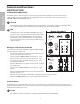
This system shows the MDR6 connected to a pair of powered speakers like the SAMSON Expedition EX20. The MONITOR OUT is connected to an external power amp, which is driving 2 monitor speakers. For inputs, one microphone is connected to channel 1’s low-impedance input, and the output of the Bass Direct Box is also connected to the Low-Impedance input on Channel 2. The Keyboards, as well as the Lead Guitar’s signal processor's outputs, are connected to the MDR6’s line inputs.
ENGLISH This system shows the MDR6 in a recording set up with the LEFT and RIGHT CONTROL ROOM output hooked up to powered studio monitors and the AUX OUT feeding a headphone mix sent to a Samson S•phone headphone amp. For inputs, a microphone is connected to channel 1’s low-impedance input, and the output of the Bass Direct Box is also connected to the LowImpedance input on channel 2. The Keyboards, as well as the Lead Guitar’s signal processor's outputs, are connected to the MDR6s line inputs.
Introduction Nous tenons à vous remercier d’avoir choisi la console Samson MDR6. La MDR6 est une console six canaux, avec 4 préamplificateurs micro à faible bruit. La MDR6 offre également une fonction HDM (Hard Disk Mode), offrant un mode d’affectation des bus et du système d’écoute prévu pour les enregistrements sur ordinateur. Le boîtier très robuste vous assurera une qualité exceptionnelle, utilisation après utilisation.
MDR6 - Caractéristiques MIC/LINE 1 MIC/LINE 2 30 GAIN CLIP CLIP -26 +26 60 5 0 5 15 0 5 5 15 MF 10 0 5 15 0 5 LF 0 5 5 80Hz 5 15 MF 15 0 5 LF 5 15 10 MF 5 2.5K 10 5 80Hz LEFT AUX RET CR OUT MIX OUT RIGHT RIGHT RIGHT AUX OUT MONO OUT 10 0 5 15 HF 5 15 12K 10 15 LEFT LINE IN 0 HF 5 10 5 2.5K 10 15 LEFT/MONO 6/R 15 12K 10 10 5/L LINE IN 0 HF 5 MASTER SECTION MIC/LINE 5/6 4/R 60 10 5 2.
Réglages et fonctions Faces avant et arrière 11 1 12 13 15 14 16 17 MIC/LINE 1 2 MIC/LINE 2 MIC/LINE 3/4 MASTER SECTION MIC/LINE 5/6 LEFT/MONO LEFT LEFT AUX OUT 18 3 30 GAIN GAIN CLIP CLIP 4 5 -26 +26 3/L 30 5/L LINE IN AUX RET CR OUT MIX OUT RIGHT RIGHT RIGHT LINE IN MONO OUT 20 60 5 -26 +26 4/R 60 6/R 21 5 0 5 6 10 0 5 7 5 12K 10 15 0 HF 5 15 10 10 10 15 0 5 15 0 5 15 10 15 LF 0 5 15 15 0 15 LF 15 10 15 0 0 5 15 5 MF
Faces avant et arrières Réglages 18 ENTRÉES ET SORTIES 2 TRACK – Connectez un lecteur DAT, cassette, Mini Disk ou système D-t-D. FACE AVANT 1 CONNECTEUR MIC/LINE – Embase combinée très faible bruit Jack/XLR pour niveaux ligne et micro 2 GAIN – Permet d’ajuster le niveau d’entrée de l’entrée ligne et micro en fonction de la source. 3 CLIP – Led rouge s’allumant lorsque le gain d’entrée est trop important. 4 AIGUS – Égaliseur aigu de voie.
Réglages et fonctions VOIES MONO Ce chapitre couvre tous les réglages et fonctions des entrées mono de la console MDR6, dont le GAIN, l’égaliseur 3 bandes, le départ AUX, RECORD, PAN et LEVEL. Les entrées 1 à 4 de la console MDR6 sont équipées de préamplificateurs de très haute qualité à transistors discrets et offrent une transparence sonore extrême, ainsi qu’une plage dynamique étendue.
RÉGLAGES ET FONCTIONS VOIES MONO 5 BALANCE (entrées stéréo uniquement) Le réglage de BALANCE de la MDR6 permet de placer un signal mono dans le champ stéréo de la sortie. Dans le cas d’un signal stéréo, le réglage de Balance centre le son entre les Bus gauche et droit. Vous pouvez créer une image stéréo en plaçant certains signaux à gauche et d’autres à droite. PAN (voies mono uniquement) Le réglage PAN de la MDR6 permet de positionner le signal d’entrée dans le champ stéréo des sorties générales.
�������������� Réglages et fonctions ��������� ���� ���� ������� ������� ������ ������� ����� ����� ����� SECTION DE SORTIE ENTRÉE/SORTIE 2 TRACK �������� La section 2 Track de la console MDR6 permet la connexion pour la lecture et l'enregistrement d'un équipement externe tel qu'un DAT, magnétophone à cassette, CD ou Mini-Disc. 9 2TK LEVEL Le potentiomètre 2TK LEVEL permet de régler le niveau du signal de l’entrée 2T IN affecté au Bus de mixage général G/D.
�������������� ��������� ���� ������� ���� Réglages et fonctions 12 SECTION DE SORTIE ������� ������ ������� ����� ����� ����� �������� Potentiomètre C/ROOM + PHONES Le potentiomètre C/ROOM + PHONES permet le réglage du niveau du signal de la sortie Control Room et du casque.
Connexions des entrées et des sorties de la MDR6 ���������� 1 ���������� ������������ ������������ 4 �������������� ��������� ���� ���� ������� ������ ������� ����� ����� ����� 9 6 7 5 ������� 2 �� �� ���� ���� ���� ���� ������� ����� ��������� ���� ������� ��� ��������� ��� ��� ������� ��� ��� �������� ��� 3 FRANÇAIS VOIES 1 À 6 (MICRO ET LIGNE) �������� 8 Les entrées de la console MDR6 sont équipées d’un connecteur mixte XLR/Jack 6,35 mm travaillant à niveau ligne h
Connexions des entrées et des sorties de la MDR6 CONNECTEURS JACKS DE SORTIE La MDR6 dispose de plusieurs connecteurs de sortie vous permettant de l’utiliser avec de nombreux équipements externes. Connectez un enregistreur de type magnétophone à cassette aux sorties 2 Track, les amplificateurs aux sorties CONTROL ROOM et MAIN, par exemple. 5 Sortie AUX Le signal de la sortie Aux est dérivé du bus auxiliaire qui est alimenté par les réglages de départ AUX Send des différentes voies d’entrées.
Utilisation de la console MDR6 UTILISATION SIMPLE Le chapitre suivant vous explique les utilisations basiques de la console MDR6. CONNEXION DE MICROS ET INSTRUMENTS 21 R Bass Guitar Lead Guitar Vocal Direct Box Signal Processor Stereo Signal SIGNAL FLOW 2. Connectez les câbles de vos micros et instruments et insérez l’autre extrémité aux entrées correspondantes de la MDR6. SIGNAL FLOW SIGNAL FLOW SIGNAL FLOW FRANÇAIS SA M SO N 1.
Utilisation de la console MDR6 ENVOI D’UN MIXAGE INDÉPENDANT AUX ENCEINTES D’ÉCOUTE Le départ auxiliaire de la console MDR6 permet d’alimenter des amplificateurs et enceintes utilisées comme retours de scène. Ceci vous permet de réaliser un mixage pour les amplificateurs/enceintes tournés vers le public et un autre pour les enceintes placées devant les musiciens. 1. Réglez le bouton AUX des voies que vous souhaitez entendre dans les retours.
Utilisation de la console MDR6 Utilisation du mode HDM (HARD DISK MODE) La console MDR6 offre un mode HDM (HARD DISK MODE) qui lui est spécifique et conçu pour son utilisation avec les systèmes d’enregistrement sur ordinateur (Direct-to-Disc). C’est la première fois qu’une telle fonction d’affectation du trajet du signal et de Monitoring est disponible sur une console de cette compacité. La fonction HDM offre un Bus d’enregistrement et un circuit d’écoute spécifique à l’utilisation en D-t-D.
Utilisation de la console MDR6 0 5 10 0 5 Enregistrement en écoutant le signal déjà enregistré lors de la première passe 15 10 15 0 15 10 15 LF 15 MF 5 2.5K 10 5 80Hz 15 15 0 5 Maintenant que vous avez enregistré votre piste de batterie, vous pouvez rajouter d’autres pistes en utilisant le mode HDM de la console MDR6. Pour cet exemple, nous allons rajouter une piste de chant en utilisant un 10micro. Suivez 10les éta10 pes ci-dessous : 5 15 0 LF 5 5 80Hz 10 15 15 AUX 1.
32 5 HF 12K MF 10 LF 5 5 5 15 20 30 40 5 10 15 20 30 40 10 15 20 30 40 21 R CHANNEL 1 L 0 REC 0 0 0 0 +26 _ _ _ _ _ _ _ _ -26 MF 10 HF 12K LF R 30 40 20 15 10 5 0 5 10 PAN 10 AUX 15 10 5 80Hz 15 10 5 2.5K 15 5 60 CHANNEL 2 10 0 0 0 5 _ _ _ _ _ _ _ _ 5 PAN 5 15 10 15 10 5 15 10 5 5 10 R 10 AUX 15 10 5 80Hz 15 10 5 2.
FRANÇAIS Ce système indique la MDR6 en configuration d’enregistrement avec les sorties CONTROL ROOM GAUCHE et DROITE connectées aux moniteurs actifs et la sortie AUX OUT alimentant un mixage pour casques affecté à l’amplificateur/distributeur de casque Samson S•phone.
Einleitung Herzlichen Glückwunsch zum Kauf des Samson MDR6 Mischpults! Der MDR6 ist ein 8-Kanal-Mischer mit 6 rauscharmen Mikrofon-Vorverstärkern. Der MDR6 verfügt auch über einen HDM (Hard Disk-Modus), der eine spezielle Monitoring- und Bussing-Betriebsart aktiviert, die optimal mit einem computergestützten Hard Disk Recorder zusammenarbeitet.
MDR6 Features ���������� ���������� ���� ���� ���� ��������� ���� � ������� ��� � �� � � � �� �� �� �� � � � �� � � � ���� � �� �� �� � � �� � �� �� �� ������� ������ ������� ����� ����� ����� ������� �������� �� � � � �� ����� ������ �� � � � ���� � �� � ���� �� �� �� ��� �� � � ���� �� � ���� ���� �� � �� ��� �� �� �� ���� �������� � �� � �� � ���� �� �� �� ��������� ��� �� ��� �� � � ���� �� ��� ������� � �� �
Regler und Funktionen Vorder- und Rückseite 11 1 12 13 15 14 16 17 MIC/LINE 1 2 MIC/LINE 2 MIC/LINE 3/4 MASTER SECTION MIC/LINE 5/6 LEFT/MONO LEFT LEFT AUX OUT 18 3 30 GAIN GAIN CLIP CLIP 4 5 -26 +26 3/L 30 5/L LINE IN AUX RET CR OUT MIX OUT RIGHT RIGHT RIGHT LINE IN MONO OUT 19 20 60 5 -26 +26 4/R 60 6/R 21 5 0 5 6 10 0 5 7 5 12K 10 15 0 HF 5 15 10 10 10 15 0 5 15 0 5 15 10 15 LF 0 5 15 15 0 15 LF 15 10 15 0 0 5 15 5
Vorder- und Rückseite Vorder- und Rückseite 18 2 TRACK INPUTS & OUTPUTS – Anschlüsse für DAT, Tape Deck, MD oder Hard Disk Recording-System. VORDERSEITE 1 MIC/LINE – Kombinierter Eingang für rauscharme MikrofonVorverstärker- und Line-Pegel-Signale. 2 GAIN – Zum Einstellen des Pegels für den Mic Preamp- und Line-Pegel-Eingang. 3 CLIP – Wenn die rote LED leuchtet, ist Mic GAIN zu hoch eingestellt. 4 HIGH FREQUENCY – Regelt das hohe Band des Channel Equalizers um +/- 15 dB bei 12 kHz.
Regler und Funktionen MONO-EINGANGSKANAL-SEKTION Der folgende Abschnitt beschreibt detailliert jedes Bauteil der MDR6 MONO-EINGANGSKANÄLE, inklusive GAIN-Regler, 3-BAND-EQ, AUX Send, RECORD-, PAN- und LEVEL-Regler. Die Eingangskanäle 1 bis 4 des MDR6 zeichnen sich durch hochwertige, getrennte Transistor-Vorverstärker mit ausgezeichneter Transparenz und erweitertem Dynamikbereich aus.
Regler und Funktionen MONO-EINGANGSKANAL-SEKTION 5 BALANCE (nur Stereo-Eingänge) Mit dem BALANCE-Regler positionieren Sie ein Mono-Eingangssignal auf dem Stereo Links/Rechts Haupt-MIX Bus. Bei Stereo-Eingangssignalen können Sie den Sound in die Mitte des Links/Rechts Mix Bus platzieren. Indem Sie die Eingangssignale nach links und rechts verteilen, können Sie ein Stereobild erzeugen.
Regler und Funktionen MASTER-SEKTION �������������� ��������� 2-SPUR EINGANG UND AUSGANG ���� ������� ���� Die 2-Spur-Sektion des MDR6 verfügt über Anschlüsse für die Wiedergabe und Aufnahme externer Geräte, wie DAT, Cassettenrecorder, CD oder Mini Disk. 9 ������� ������ ������� ����� ����� ����� �������� 2T LEVEL Mit dem 2-Track to Mix-Regler bestimmen Sie den Signalanteil, der von den 2T IN-Buchsen zum L/R Mix HauptBus geleitet wird.
��������� ���� ������� ���� Regler und Funktionen 12 ������� ������ ����� ����� ������� MASTER-SEKTION �������� ����� C/ROOM + PHONES Mit dem C/ROOM + PHONES-Regler stellen Sie den Pegel des Signals ein, das zu den Control Room- und Kopfhörer-Ausgängen geleitet wird. 13 +48V - Phantom Power LED Wenn die +48V LED leuchtet, wird 48 Volt Phantomspannung für den Betrieb von Kondensatormikrofonen an die Mikrofonvorverstärker angelegt.
MDR6 Eingänge und Ausgänge ���������� 1 ���������� ������������ �������������� ������������ 4 ��������� ���� ���� ������� ������ ������� ����� ����� ����� 9 6 5 ������� 2 �� �� ���� ���� ���� ���� ������� ����� ��������� ���� ������� ��� ��������� ��� ��� ��� ������� ��� �������� ��� 3 CHANNEL 1–6 MIC/LINE-EINGÄNGE 7 �������� 8 Die “Kombi”-Anschlüsse (XLR & 1/4” Klinke) der 6 Eingangskanäle verfügen über einen LINE-Pegel-Eingang (Hi-Z, hochohmig) und einen MIC-Pegel-E
MDR6 Eingänge und Ausgänge EXTERNE AUSGANGSBUCHSEN Der MDR6 bietet auch mehrere Ausgänge für den Anschluss externer Geräte. Sie können ein Stereo-Aufnahmegerät, z. B. Cassettenrecorder, an die 2 Track-Buchsen sowie zusätzliche Endstufen an die CONTROL ROOM- und MAINAusgangsbuchsen anschließen. 5 AUX-Ausgang Das am AUX-Ausgang anliegende Signal kommt vom AUX Bus, der vom AUX Send der Eingangskanäle gespeist wird.
MDR6 bedienen ELEMENTARE BEDIENUNG Der folgende Abschnitt erklärt die elementare Bedienung des MDR6. MIKROFONE UND INSTRUMENTE ANSCHLIESSEN SA M SO N 21 R 1. Bevor Sie Mikrofone oder Instrumente anschließen, müssen alle Systemkomponenten, inklusive MDR6, ausgeschaltet sein. Stellen Sie außerdem sicher, dass die Linken und Rechten MIX Fader ganz nach unten geschoben sind. E-Bass Direct Box Signalprozessor Stereo-Signal SIGNALFLUSS SIGNALFLUSS SIGNALFLUSS SIGNALFLUSS 2.
MDR6 bedienen SEPARATE MISCHUNG ZU DEN MONITOR-LAUTSPRECHERN LEITEN Über den AUX Send-Weg können Sie ein separates Set von Verstärkern und Lautsprechern ansteuern, die als Bühnenmonitore dienen. Dadurch lässt sich eine Stereo-Mischung für die auf das Publikum gerichteten Verstärker/ Lautsprecher aufbauen und eine zweite Mono-Mischung für die auf die Musiker gerichteten Verstärker/Lautsprecher. 1. Drehen Sie die AUX-Regler der Kanäle auf, die in den Monitorlautsprechern hörbar sein sollen.
MDR6 bedienen HDM (HARD DISK-MODUS) einsetzen Der MDR6 bietet einen exklusiven HDM (HARD DISK-MODUS), der eine Schnittstelle zu computergestützten Hard DiskRecordern bildet. Noch nie wurde ein derart flexibles Routing und Monitoring in einen so kleinen Mischer integriert. Mit seinem speziellen Aufnahme-Bus und beispiellosen Monitoring zur Lösung von Latenzproblemen stellt der HDM eine nahtlose Lösung für Aufnahmen und Overdubs mittels Hard Disk Recorder dar.
MDR6 bedienen 0 5 10 0 5 15 15 10 0 0 5 15 0 15 15 Verbinden Sie den Ausgang Ihrer Computer Soundkarte mit 2-Track In des MDR6 und anschließend den 2-TrackAUX Ausgang mit dem Eingang der Soundkarte. 3. Drücken Sie die HDM-Taste. 4. L R Drücken Sie die RECORD-Taste von Kanal 1. Die REC LED des Eingangskanals blinkt, um anzuzeigen, dass der Kanal dem RECORD Bus zugewiesen ist. REC 6.
Bei diesem System ist der MDR6 an ein Paar Aktivlautsprecher, z. B. SAMSON Expedition EX20, angeschlossen. MONITOR OUT ist mit einer externen Endstufe verbunden, die 2 Monitorlautsprecher betreibt. Bei den Eingängen ist ein Mikrofon mit dem niederohmigen Eingang von Kanal 1 und der Ausgang der Bass Direct Box ist mit dem niederohmigen Eingang von Kanal 2 verbunden. Die Keyboards und die Ausgänge des Signalprozessors der Lead Guitarre sind an die Line-Eingänge des MDR6 angeschlossen.
Bei diesem Aufnahme-Setup ist der LINKE und RECHTE CONTROL ROOM Ausgang des MDR6 mit Studio-Aktivmonitoren verbunden, wobei der AUX OUT-Weg eine Kopfhörermischung in einen Samson S•phone Kopfhörerverstärker einspeist. Bei den Eingängen ist ein Mikrofon mit dem niederohmigen Eingang von Kanal 1 und der Ausgang der Bass Direct Box ist mit dem niederohmigen Eingang von Kanal 2 verbunden. Die Keyboards und die Ausgänge des Signalprozessors der Lead Guitarre sind an die Line-Eingänge des MDR6 angeschlossen.
Introducción ¡Enhorabuena por la compra de su mezclador Samson MDR6! El MDR6 es un mezclador de ocho canales, con seis preamplificadores de micrófono de bajo. El MDR6 también dispone del modo HDM (modo de disco duro), que cuando está activado, le ofrece un modo especial de monitorización y de control de buss totalmente adecuado para la interconexión con una grabadora de disco duro con base en ordenador.
Características del MDR6 ���������� ���������� ���� ���� ���� ��������� ���� � ������� ��� � �� � � � �� �� �� �� � � � �� � � � ���� � �� �� �� � � �� � �� �� �� ������� ������ ������� ����� ����� ����� ������� �������� �� � � � �� ����� ������ �� � � � ���� � �� � ���� �� �� �� ��� �� � � ���� �� � ���� ���� �� � �� ��� �� �� �� ���� �������� � �� � �� � ���� �� �� �� ��������� ��� �� ��� �� � � ���� �� ��� �������
Controles y Funciones Distribución del panel frontal y trasero 11 1 12 13 15 14 16 17 MIC/LINE 1 2 MIC/LINE 2 MIC/LINE 3/4 MASTER SECTION MIC/LINE 5/6 LEFT/MONO LEFT LEFT AUX OUT 18 3 30 GAIN GAIN CLIP CLIP 4 5 -26 +26 3/L 30 5/L LINE IN AUX RET CR OUT MIX OUT RIGHT RIGHT RIGHT LINE IN MONO OUT 19 20 60 5 -26 +26 4/R 60 6/R 21 5 0 5 6 10 0 5 7 5 12K 10 15 0 HF 5 15 10 10 10 15 0 5 15 0 5 15 10 15 LF 0 5 15 15 0 15 LF 15 10 1
Controles y Funciones Distribución del panel frontal y trasero 18 ENTRADAS Y SALIDAS 2 TRACK – Conecte un DAT, pletina, Mini Disk o sistema de grabación en HD. PANEL FRONTAL 1 MIC/LINE – Conector combinado con previo de micro de bajo nivel de ruido y entradas de nivel de línea. 2 GAIN – Se usa para ajustar el nivel de entrada del previo de micro y de la entrada de línea. 3 CLIP – El piloto rojo se ilumina para indicar que la ganancia de micro ha sido ajustada demasiado alto.
Controles y Funciones SECCION DE CANAL DE ENTRADA MONO La sección siguiente le describe cada una de las partes de los CANALES DE ENTRADA MONO del MDR6 incluyendo el control GAIN, el EQ de 3 bandas, el envío AUX y los controles RECORD, PAN y LEVEL. Los canales de entrada uno a cuatro del MDR6 disponen de preamplificadores de alta calidad y con transistores independientes que le ofrecen una gran transparencia y un rango dinámico ampliado.
Controles y Funciones MONO INPUT CHANNEL SECTION 5 BALANCE (Solo entradas stereo) El control BALANCE del MDR6 se usa para colocar una entrada mono en el bus MIX principal izquierdo y derecho, Para una entrada stereo, el control de balance se usa para centrar el sonido en el bus de mezcla izquierdo y derecho. Puede crear una imagen stereo colocando unas señales de entrada a la izquierda y otras a la derecha.
Controles y Funciones SECCION MASTER ENTRADA Y SALIDA 2 TRACK �������������� ��������� ���� ���� ������� ������� ������ ������� La sección 2 Track del MDR6 le ofrece las conexiones para la reproducción y grabación desde una unidad exterior como un DAT, pletina, CD o Mini Disk. 9 2TK LEVEL El control 2TK LEVEL se usa para ajustar la cantidad de señal enviada desde los conectores 2T IN al bus de mezcla principal I/D.
�������������� ��������� ���� ������� ���� Controles y Funciones SECCION MASTER 12 ������� ������ ������� ����� ����� ����� �������� C/ROOM + PHONES El control C/ROOM + PHONES se usa para ajustar el nivel enviado a las salidas de la sala de control, y también al conector de auriculares.
Conexiones de entrada y salida del MDR6 ���������� 1 ���������� ������������ �������������� ������������ 4 ��������� ���� ���� ������� ������ ������� ����� ����� ����� 9 6 5 ������� 2 �� �� ���� ���� ���� ���� ������� ����� ��������� ���� ��� ������� ��� �������� �������� 3 ������� ��� ��������� ��� ��� ��� ENTRADAS MIC y LINE del CANAL 1–6 7 8 Los seis canales de entrada del MDR6 disponen de un conector "Combie" (combinación de XLR y 6,3 mm) con una entrada de nivel d
Conexiones de entrada y salida del MDR6 CLAVIJAS DE SALIDA EXTERNA El MDR6 dispone de varios conectores de salida que le permiten interconectar una gran variedad de unidades exteriores. Puede conectar una unidad de grabación exterior como una grabadora de cassette a las tomas 2 Track, o etapas de potencia adicionales a las salidas CONTROL ROOM y MAIN. 5 Salida AUX La señal presente en la salida AUX es enviada desde el bus AUX, que recibe su señal del envío AUX de los canales de entrada.
Manejo del MDR6 FUNCIONAMIENTO BASICO En la sección siguiente le explicamos el funcionamiento básico del MDR6. CONEXION DE MICROFONOS E INSTRUMENTOS SA M SO N 21 R 1. Antes de conectar micros o instrumentos, asegúrese de que todos los componentes de su sistema estén apagados, incluyendo el propio MDR6. Además, asegúrese también de que los faders MIX izquierdo y derecho estén abajo del todo.
Manejo del MDR6 ENVIO DE UNA MEZCLA INDEPENDIENTE A LOS MONITORES Puede usar el envío AUX del MDR6 para dar señal a un grupo de amplificadores y altavoces independientes que use como monitores. Esto le permite tener una mezcla stereo para los amplificadores y cajas que dan señal al público y la otra mezcla mono para las etapas y monitores que dan señal a los músicos. 1. Suba los controles AUX de los canales que quiera escuchar a través de los monitores.
Manejo del MDR6 Uso del HDM (MODO DE DISCO DURO) El MDR6 incluye un modo HDM (MODO DE DISCO DURO) exclusivo que ha sido diseñado para interconectar esta unidad con grabadoras de disco duro con base en ordenadores. Nunca hasta la fecha había sido incluido un sistema de monitorización y direccionamiento tan flexible en una mesa tan pequeña.
Manejo del MDR6 0 5 10 0 5 10 15 0 15 0 MF 5 5 2.5K 10 15 10 15 LF 5 Ahora que ya ha grabado una pista básica de ritmo, puede sobredoblar pistas adicionales usando el5HDM del MDR6. Para5 este ejemplo, vamos a sobredoblar una pista vocal usando un micrófono. Vea estos pasos. 10 10 10 15 0 LF 5 80Hz 80Hz 1. 2. 15 la salida 15 Conecte la salida de la tarjeta de sonido de su ordenador a la entrada 2-Track del MDR6 y después 2-Track AUX del MDR6 a la entrada de la misma tarjeta de sonido.
Aquí mostramos un MDR6 conectado a un par de recintos autoamplificados como los SAMSON Expedition EX20. La salida MONITOR OUTestá conectada a una etapa de potencia exterior, que da señal a 2 monitores. En cuanto a las entradas, un micrófono está conectado a la entrada de baja impedancia del canal 1 y la salida del Direct Box del bajo está conectada también a la entrada de baja impedancia del canal 2.
SIGNAL FLOW 65 5 5 5 60 HF 12K 5 5 0 5 5 5 REC 0 0 0 0 +26 _ _ _ _ _ _ _ _ -26 30 HF 12K LF R 30 40 20 15 10 5 0 5 10 PAN 10 AUX 15 10 5 80Hz 15 10 5 2.5K MF 10 15 5 60 CHANNEL 2 30 40 20 30 40 CHANNEL 1 15 20 10 15 30 40 10 15 20 10 5 5 0 0 L 0 15 10 15 10 5 R PAN 10 5 5 15 10 10 _ _ _ _ _ _ _ _ LF AUX 15 10 5 80Hz 15 10 5 2.
MDR6-Wiring Guide /Plan de câblage /Verdrahtung / Guía de cableado del CONNECTING THE MDR8 The are several ways to interface the MDR6 to support a variety of applications. The MDR8 features balanced inputs and outputs, so connecting balanced and unbalanced signals is possible.
MDR6 Specifications Frequency Response (Trim @ Min, unity gain ± 3 dB) Mic to Main Line to Main Aux Return to Main Line to Aux Send 5 Hz - 54 kHz 5 Hz - 54 kHz 5 Hz - 98 kHz 5 Hz - 57 kHz T.H.D. (Trim @ Min, +4dBu output, unity gain, 1 kHz w/30 kHz LPF) Mic/Line to Main (Mono Ch) Line to Main (Stereo Ch) Line to Aux Send 0.0% 0.02% 0.
MDR6 - Caractéristiques Bande passante (gain au min., gain unitaire ± 3 dB) Entre entrée Mic et sorties Entre entrée Line et sorties Entre Aux Return et sorties Entre Line et Aux Send 5 Hz - 54 kHz 5 Hz - 54 kHz 5 Hz - 98 kHz 5 Hz - 57 kHz DHT (gain au min.
MDR6 Technische Daten Frequenzgang (Trim @ Min, Unity Gain ± 3 dB) Mic zu Main Line zu Main Aux Return zu Main Line zu Aux Send 5 Hz - 54 kHz 5 Hz - 54 kHz 5 Hz - 98 kHz 5 Hz - 57 kHz Klirrfaktor (Trim @ Min, +4 dBu Ausgang, Unity Gain, 1 kHz mit/30 kHz LPF) Mic/Line zu Main (Mono-Kanal) Line zu Main (Stereo-Kanal) Line zu Aux Send 0.02 % 0.02 % 0.02 % Äquivalentes Eingangsrauschen ("A" Filter ein, Eingang kurzgeschlossen) Mic Line -128 dB -104 dB Max.
Especificaciones técnicas del MDR6 Respuesta de frecuencia (Trim @ mín, ganancia unitaria ± 3 dB) Micro a principal Línea a principal Retorno auxiliar a principal Línea a envío auxiliar 5 Hz - 54 kHz 5 Hz - 54 kHz 5 Hz - 98 kHz 5 Hz - 57 kHz T.H.D. (Trim @ Mín, Salida +4dBu, ganancia unitaria, 1 kHz w/30 kHz LPF) Micro/línea a principal (canal mono) Línea a principal (canal stereo) Línea a envío auxiliar 0.02% 0.02% 0.
71 RIGHT LEFT MONO RIGHT LEFT MONO Line Mic Line Mic Ch 5/6 Input Ch 3/4 Input Ch 2 Input Ch 1 Input +48 + + +48 + + +48 + + +48 + + Trim Trim Trim Trim PEAK PEAK PEAK PEAK Equalizer Equalizer Equalizer Equalizer MDR6 BLOCK DIAGRAM Volume Volume Volume Volume AUX Balance AUX Balance AUX Pan Record AUX Pan Record AUX return HDR MODE 2 TK To Mix Main Mix 2TK IN logic control MIX L MIX R AUX 1 2TK R 2 TK L 2TK Send Aux Send 2 Tk To Control Room Phones
Notes 72
Samson Technologies Corp. 575 Underhill Blvd. P.O. Box 9031 Syosset, NY 11791-9031 Phone: 1-800-3-SAMSON (1-800-372-6766) Fax: 516-364-3888 www.samsontech.