INPUT / OUTPUT LEVEL dB -18 -6 0 +6 +9 GAIN REDUCTION dB -24 -12 -6 -4 -2 INPUT / OUTPUT LEVEL dB -18 -6 0 +6 +9 GAIN REDUCTION dB -24 -12 -6 -4 -2 INPUT / OUTPUT LEVEL dB -18 -6 0 +6 +9 GAIN REDUCTION dB -24 -12 -6 -4 -2 INPUT / OUTPUT LEVEL dB -18 -6 0 +6 +9 POWER 4 CHANNEL COMPRESSOR GATE COMPRESSOR / LIMITER TRIGGER THRESHOLD RATIO 20 -10 4:1 GATE 50 0 STEREO LINK CH 1 METER 10 2 6 COMPRESSOR / LIMITER TRIGGER THRESHOLD RATIO 0 20 -10 4:1 I/O -30 EXPANDER/GATE OUTPUT IN
Safety Instructions Caution: To reduce the hazard of electrical shock, do not remove cover or back. RISK OF ELECTRIC SHOCK DO NOT OPEN WARNING DO NOT EXPOSE THIS EQUIPMENT TO RAIN OR MOISTURE AVIS RISQUE DE CHOC ELECTRONIQUE NE PAS OUVRIR No user serviceable parts inside. Please refer all servicing to qualified personnel.
Table of Contents Table des matières Inhalt ENGLISH Contenido DEUTSCHE Forward by Ray Kennedy 3 Vorwort von Ray Kennedy 32 Introduction 4 S•com 4 Features 33 S•com 4 Features 5 Regler und Funktionen Vorderseite Rückseite Controls and Functions Front Panel Layout Rear Panel Layout Operating the S•com 4 Setting Up the S•com 4 Compressing A Signal Gating A Signal Using The Expander Using the Enhancer 6-7 6-7 8 8 9 9 10 Dynamics Processing 101 11-12 Applications 13-14 System Set-ups 15-16
Forward By Ray Kennedy Peak limiting and soft compression are basically good for maximizing levels to tape or disk without a lot of coloration. Essentially knocking the peaks down and bringing the quieter portions of a sound up louder by narrowing the dynamic range. Slow attack and fast release times allow for more transparent sound. I personally like the sound of compression and use it at times to extremes.
ENGLISH Introduction Thank you for purchasing the Samson S•com 4 dynamics processor. The Samson S•com 4 is a one-space, four channel dynamics processor optimized for recording, live sound reinforcement systems, DJ set-ups and commercial installations. The S•com 4 is a complete dynamics processing solution offering four channels of full function Compressor, Expander/Gate, and Enhancer. S•com 4’s convenient meters provide instant status of important gain management settings.
S•com 4 Features GAIN REDUCTION dB -24 -12 -6 -4 -2 INPUT / OUTPUT LEVEL dB -18 -6 0 +6 +9 GAIN REDUCTION dB -24 -12 -6 -4 -2 INPUT / OUTPUT LEVEL dB -18 -6 0 +6 +9 GAIN REDUCTION dB -24 -12 -6 -4 -2 INPUT / OUTPUT LEVEL dB -18 -6 0 +6 +9 GAIN REDUCTION dB -24 -12 -6 -4 -2 INPUT / OUTPUT LEVEL dB -18 -6 0 +6 +9 POWER EXPANDER/GATE 4 CHANNEL COMPRESSOR GATE COMPRESSOR / LIMITER TRIGGER THRESHOLD RATIO 20 -10 4:1 GATE 50 0 STEREO LINK CH 1 METER 10 2 6 COMPRESSOR / LIMITER TRIGGER TH
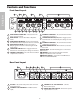
Controls and Functions Front Panel Layout 2 ENGLISH 1 4 3 5 GAIN REDUCTION dB -24 -12 -6 -4 -2 EXPANDER/GATE 4 CHANNEL COMPRESSOR GATE INPUT / OUTPUT LEVEL dB -18 -6 0 +6 +9 COMPRESSOR / LIMITER TRIGGER THRESHOLD RATIO 20 -10 4:1 0 GAIN REDUCTION dB -24 -12 -6 -4 -2 STEREO LINK CH 1 METER GATE 50 6 6 COMPRESSOR / LIMITER OUTPUT TRIGGER THRESHOLD RATIO 0 20 -10 4:1 I/O 10 2 -30 EXPANDER/GATE INPUT / OUTPUT LEVEL dB -18 -6 0 +6 +9 IN/OUT 1 -10 +10 0 EXP T OUTPUT 0 GA
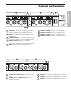
Controls and Functions 7 INPUT / OUTPUT LEVEL dB -18 -6 0 +6 +9 GAIN REDUCTION dB -24 -12 -6 -4 -2 11 INPUT / OUTPUT LEVEL dB -18 -6 0 +6 +9 POWER POWER XPANDER/GATE COMPRESSOR / LIMITER TRIGGER THRESHOLD RATIO 20 -10 4:1 METER GATE 0 STEREO LINK CH 3 10 2 6 COMPRESSOR / LIMITER OUTPUT TRIGGER THRESHOLD RATIO 0 20 -10 4:1 IN/OUT 3 I/O -30 EXPANDER/GATE -10 +10 METER 0 OUTPUT 0 GATE 50 CH 4 I/O -30 10 2 6 -10 +10 IN/OUT 4 OFF +10 -40 dB +20 1 dB -20 dB RELEAS
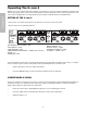
Operating The S•com 4 ENGLISH Whether you are an experienced audio engineer, just starting out, or you just want to experiment, follow the steps below to get going. Further sections in this manual will cover basic dynamics and the associated parameters, system set-ups and applications for using dynamics processing in recording and live sound applications. SETTING UP THE S•com 4 • Connect one set of inputs and outputs to the Channel 1 connectors on the rear panel.
Operating The S•com 4 • GAIN REDUCTION dB -24 -12 -6 -4 -2 EXPANDER/GATE INPUT / OU -18 -6 COMPRESSOR / LIMITER TRIGGER THRESHOLD RATIO 20 -10 4:1 METER GATE 50 0 I/O -30 10 2 OFF +10 -40 dB +20 -1 6 1 dB dB RELEASE ENHANC GATING A SIGNAL Unwanted noises, buzzes and hisses can be easily removed by using S•com 4’s GATE. The idea is to have the Gate open only when your desired signal is playing and to mute off (Gate closed) the unwanted noise, buzz and hiss.
Operating The S•com 4 ENGLISH USING THE ENHANCER The S•com 4’s ENHANCER switch can be engaged to activate the EFR (Enhanced Frequency Recovery) circuit. By engaging the ENHANCER, the S•com 4 EFR restores the high frequency content that can be lost when high gain reduction is applied. The S•com 4 EFR achieves this by adding back the high-end of the original signal in an amount that is equal to the amount of gain reduction.
Dynamics Processing 101 COMPRESSOR A good compressor is one of the most useful tools in live sound and recording. Compressors are used to control the dynamic range of a signal, which offers a variety of benefits including leveling a signal that’s being recorded, having an instrument sit in the mix, and increasing the loudness of a sound system to name a few. Drastic amounts of compression will also result in an effect that becomes more of a sound, than just controlling gain.
Dynamics Processing 101 - Continued ENGLISH Soft-Knee / Hard-Knee In order to prevent harsh, unnatural envelopes on compressed signals, sophisticated dynamics processors like the S•com 4 feature an SKD (Smart Knee Detector) or automatic knee circuit. The Smart Knee Detector automatically switches from Soft-Knee when the signal is less than 10 dB over Threshold, to Hard-Knee when the signal is 10db above Threshold.
Applications Using the Expander/Gate to Remove Hiss and Noise The S•com 4 is an extremely useful tool in reducing the level of unwanted noises. By using the Expander/Gate you can effectively fade the noise into the noise floor or abruptly turn the unwanted signal completely off. Now let’s say you’re attempting to remove the pick-up noise and hum from a guitar track that was recorded through a loud amplifier.
Applications ENGLISH Leveling a Vocal Track When recording a vocal track, the vocalist may change the distance between them and the microphone, or they may naturally have a lot of dynamic range in their performance. In either case, the sound engineer must decide how much compression should be used to balance the natural performance and printing a good level to tape or disk. Adjust the S•com 4’s Ratio to 4:1. The S•com 4 uses the AEG (Auto Envelope Generator) for automatic attack and release.
S•com 4 System Set-Ups LIVE SOUND SYSTEM WITH STEREO COMPRESSION Left High / Mid SAMSON TECHNOLOGIES CORP., NEW YORK, U.S.A. PL 1602 16 CHANNEL LINE MIXER S/N POWER MIC 1 INPUTS BALANCED 10KΩ -30 to +4db TIP + RING - SLEEVE GND.
LIVE SOUND SYSTEM WITH MULTIBAND COMPRESSION PL1602 Mixer Left High / Mid SAMSON TECHNOLOGIES CORP., NEW YORK, U.S.A. PL 1602 16 CHANNEL LINE MIXER S/N POWER MIC 1 INPUTS BALANCED 10KΩ -30 to +4db TIP + RING - SLEEVE GND.
S•com 4 Connections CONNECTING THE S•com 4 INSERT POINTS Many mixers today provide channel and bus or group inserts. Insert points are input and output patch points that interrupt the channel or bus signal so that external processors can be connected. Channel insert points are ideal for connecting to when using the S•com 4 to process a single channel like a vocal, bass or guitar. Bus insert points are ideal for compressing groups of instruments like vocals, strings or drums.
Note de Ray Kennedy FRANÇAIS Les compresseurs et limiteurs sont des outils fondamentaux pour l’enregistrement et le mixage. Beaucoup ne réalisent pas à quel point ils sont essentiels. Pour moi, la compression est bien plus qu’un simple processeur de dynamique. Chaque modèle possède son propre son et se révèle idéal pour des applications bien spécifiques. C’est pourquoi je dispose d’un choix d’environ quarante compresseurs.
Caractéristiques du S•com 4 GAIN REDUCTION dB -24 -12 -6 -4 -2 INPUT / OUTPUT LEVEL dB -18 -6 0 +6 +9 GAIN REDUCTION dB -24 -12 -6 -4 -2 INPUT / OUTPUT LEVEL dB -18 -6 0 +6 +9 GAIN REDUCTION dB -24 -12 -6 -4 -2 INPUT / OUTPUT LEVEL dB -18 -6 0 +6 +9 GAIN REDUCTION dB -24 -12 -6 -4 -2 INPUT / OUTPUT LEVEL dB -18 -6 0 +6 +9 POWER EXPANDER/GATE 4 CHANNEL COMPRESSOR GATE COMPRESSOR / LIMITER TRIGGER THRESHOLD RATIO 20 -10 4:1 GATE 50 0 STEREO LINK CH 1 METER 10 2 6 COMPRESSOR / LIMITER
Face avant du S•com 4 2 1 4 3 5 GAIN REDUCTION dB -24 -12 -6 -4 -2 EXPANDER/GATE 4 CHANNEL COMPRESSOR GATE INPUT / OUTPUT LEVEL dB -18 -6 0 +6 +9 COMPRESSOR / LIMITER TRIGGER THRESHOLD RATIO 20 -10 4:1 0 GAIN REDUCTION dB -24 -12 -6 -4 -2 STEREO LINK CH 1 METER GATE 50 6 10 2 6 COMPRESSOR / LIMITER OUTPUT TRIGGER THRESHOLD RATIO 0 20 -10 4:1 I/O -30 EXPANDER/GATE INPUT / OUTPUT LEVEL dB -18 -6 0 +6 +9 IN/OUT 1 -10 0 EXP T OUTPUT 0 GATE 50 +10 CH 2 METER I/O -30
Face arrière du S•com 4 7 GAIN REDUCTION dB -24 -12 -6 -4 -2 10 9 8 INPUT / OUTPUT LEVEL dB -18 -6 0 +6 +9 GAIN REDUCTION dB -24 -12 -6 -4 -2 11 INPUT / OUTPUT LEVEL dB -18 -6 0 +6 +9 POWER POWER XPANDER/GATE COMPRESSOR / LIMITER TRIGGER THRESHOLD RATIO 20 -10 4:1 METER GATE 0 STEREO LINK CH 3 10 2 6 COMPRESSOR / LIMITER OUTPUT TRIGGER THRESHOLD RATIO 0 20 -10 4:1 IN/OUT 3 I/O -30 EXPANDER/GATE -10 +10 METER 0 OUTPUT 0 GATE 50 CH 4 I/O -30 10 2 6 -10 +10 IN/OUT
Utilisation du S•com 4 Que vous soyez un ingénieur du son expérimenté ou amateur, suivez les étapes ci-dessous pour configurer votre appareil. Les sections suivantes définissent les principes de la dynamique et les paramètres associés, ainsi que les configurations système et les applications de traitement de la dynamique en enregistrement et sur scène. CONFIGURATION DU S•com 4 • Reliez les entrées/sorties aux connecteurs du canal 1 en face arrière.
Utilisation du S•com 4 • À présent, tournez progressivement le potentiomètre THRESHOLD et écoutez la compression obtenue. Vous disposez d’une représentation visuelle de la compression sur l’afficheur GAIN REDUCTION.
Utilisation du S•com 4 UTILISATION DE L’ENHANCER Appuyez sur la touche ENHANCER du S•com 4 (position enfoncée) pour activer le circuit EFR (Enhanced Frequency Recovery). Lorsque l’Enhancer est activé, le circuit EFR du S•com 4 rétablit le contenu hautes fréquences qui est perdu lorsqu’une forte réduction de gain est appliquée. Le circuit EFR du S•com 4 restaure les aigus du signal initial en prenant une valeur proportionnelle à la réduction de gain.
Éléments de base sur les processeurs de dynamique Pour comprendre les notions relatives au traitement de la dynamique, nous devons tout d’abord comprendre ce qu’est la dynamique. La dynamique ou plage dynamique d’un signal ou d’un appareil audio correspond à la différence entre le niveau le plus faible et le niveau le plus élevé du signal de sortie. Le traitement de la dynamique est destiné à modifier cette différence de niveau.
Éléments de base sur les processeurs de dynamique - Suite Soft-Knee/Hard-Knee Pour éviter les enveloppes dures ou non naturelles sur les sons compressés, les processeurs de dynamique sophistiqués, comme le S•com 4, sont équipés d’un détecteur intelligent Smart Knee (SKD), soit un circuit Knee automatique. Le SKD sélectionne automatiquement le mode Soft Knee lorsque le signal est inférieur à 10 dB audessus du seuil, et le mode Hard Knee lorsque le signal atteint les 10 dB au-dessus du seuil.
Applications Utilisation de l’expanseur/Noise Gate pour supprimer le souffle et le bruit Le S•com 4 s’avère être un outil très utile pour réduire le niveau des bruits parasites. Grâce à l’expanseur/Noise Gate, vous pouvez occulter les bruits parasites dans le bruit de fond ou les supprimer complètement. Vous souhaitez par exemple réduire la diaphonie ou la reprise de signaux non souhaités par un micro, phénomènes qui se produisent lorsque différents instruments sont très proches durant l’enregistrement.
Applications Niveler la dynamique d’une piste de chant Lorsque vous enregistrez une piste de chant, il se peut que le chanteur se déplace plus ou moins loin du micro ou il se peut que l’enregistrement ait naturellement une plage dynamique importante. Le cas échéant, l’ingénieur du son doit décider de la compression à appliquer pour équilibrer l’enregistrement sur bande ou sur disque. Configurez le S•com 4 avec des temps d’attaque et de rétablissement moyens et un taux de compression de 4:1.
Configurations du système S•com 4 SYSTÈME DE SONORISATION DE SCÈNE AVEC COMPRESSION STÉRÉO PL1602 M langeur Gauche : Aigus/M diums SAMSON TECHNOLOGIES CORP., NEW YORK, U.S.A. PL 1602 16 CHANNEL LINE MIXER S/N POWER MIC 1 INPUTS BALANCED 10KΩ -30 to +4db TIP + RING - SLEEVE GND.
Configurations du système S•com 4 SYSTÈME DE SONORISATION LIVE AVEC COMPRESSION MULTIBANDE PL1602 M langeur Gauche : Aigus/M diums SAMSON TECHNOLOGIES CORP., NEW YORK, U.S.A. PL 1602 16 CHANNEL LINE MIXER S/N POWER MIC 1 INPUTS BALANCED 10KΩ -30 to +4db TIP + RING - SLEEVE GND.
Connexions du S•com 4 CONNEXION DU S•com 4 Il existe plusieurs façons d’intégrer le S•com 4 à différentes applications. Le S•com 4 est équipé d’entrées/sorties à symétrie électronique. Ainsi, la connexion de signaux symétriques et asymétriques peut se faire sans perte de signal. Le S•com 4 peut être relié à un seul instrument, en le connectant aux points d’insertion d’un canal, ou à un système de mixage complet, entre les sorties d’une console et un amplificateur de puissance ou un égaliseur.
Vorwort von Ray Kennedy Kompressoren und Limiter zählen bei der Aufnahme und Mischung zu den wichtigsten verfügbaren Tools und sind viel nützlicher, als man glaubt. Für mich ist Kompression eher ein Sound als ein Gerät zur Dynamiksteuerung. Da jedes Modell einen eigenen Klang und idealen Anwendungsbereich besitzt, arbeite ich mit einer Auswahl von etwa 40 eigenen Kompressoren.
S•com 4 Features GAIN REDUCTION dB -24 -12 -6 -4 -2 INPUT / OUTPUT LEVEL dB -18 -6 0 +6 +9 GAIN REDUCTION dB -24 -12 -6 -4 -2 INPUT / OUTPUT LEVEL dB -18 -6 0 +6 +9 GAIN REDUCTION dB -24 -12 -6 -4 -2 INPUT / OUTPUT LEVEL dB -18 -6 0 +6 +9 GAIN REDUCTION dB -24 -12 -6 -4 -2 INPUT / OUTPUT LEVEL dB -18 -6 0 +6 +9 POWER EXPANDER/GATE 4 CHANNEL COMPRESSOR GATE COMPRESSOR / LIMITER TRIGGER THRESHOLD RATIO 20 -10 4:1 GATE 50 0 STEREO LINK CH 1 METER 10 2 6 COMPRESSOR / LIMITER TRIGGER TH
S•com 4 Vorderseite 2 1 4 3 5 GAIN REDUCTION dB -24 -12 -6 -4 -2 EXPANDER/GATE 4 CHANNEL COMPRESSOR GATE INPUT / OUTPUT LEVEL dB -18 -6 0 +6 +9 COMPRESSOR / LIMITER TRIGGER THRESHOLD RATIO 20 -10 4:1 0 GAIN REDUCTION dB -24 -12 -6 -4 -2 STEREO LINK CH 1 METER GATE 50 6 10 2 6 COMPRESSOR / LIMITER OUTPUT TRIGGER THRESHOLD RATIO 0 20 -10 4:1 I/O -30 EXPANDER/GATE INPUT / OUTPUT LEVEL dB -18 -6 0 +6 +9 IN/OUT 1 -10 0 EXP T OUTPUT 0 GATE 50 +10 CH 2 METER I/O -30 10
S•com 4 Rückseite 7 GAIN REDUCTION dB -24 -12 -6 -4 -2 10 9 8 INPUT / OUTPUT LEVEL dB -18 -6 0 +6 +9 GAIN REDUCTION dB -24 -12 -6 -4 -2 11 INPUT / OUTPUT LEVEL dB -18 -6 0 +6 +9 POWER POWER XPANDER/GATE COMPRESSOR / LIMITER TRIGGER THRESHOLD RATIO 20 -10 4:1 METER GATE 0 STEREO LINK CH 3 10 2 6 COMPRESSOR / LIMITER OUTPUT TRIGGER THRESHOLD RATIO 0 20 -10 4:1 IN/OUT 3 I/O -30 EXPANDER/GATE -10 +10 METER 0 OUTPUT 0 GATE 50 CH 4 I/O -30 10 2 6 -10 +10 IN/OUT 4 OFF
S•com 4 bedienen Gleichgültig ob Sie ein erfahrener Tontechniker sind oder sich gerade in die Materie einarbeiten oder einfach experimentieren möchten, gehen Sie anfänglich wie unten beschrieben vor. Kommende Abschnitte dieses Handbuchs befassen sich mit Dynamik-Grundlagen und den zugehörigen Parametern, Systemeinrichtungen sowie Anwendungsmöglichkeiten für die Dynamikbearbeitung bei Aufnahmen und Live-Beschallungen.
S•com 4 bedienen • Drehen Sie jetzt den THRESHOLD-Pegel langsam zurück und achten Sie auf die Kompression. Optisch wird die Kompressionsstärke auf der GAIN REDUCTION-Anzeige dargestellt.
S•com 4 bedienen ENHANCER EINSETZEN Mit der ENHANCER-Taste des S•com 4 können Sie die EFR (Enhanced Frequency Recovery) Schaltung aktivieren. Durch Aktivieren des ENHANCERs stellt die S•com 4 EFR-Funktion den Höhenanteil wieder her, der bei starker Gain-Reduzierung verloren gehen kann. Hierzu fügt die S•com 4 EFR-Funktion dem Originalsignal wieder Höhen in einer Stärke hinzu, die der Stärke der Gain-Reduzierung entspricht.
Dynamikbearbeitung 101 Um die Bearbeitung der Dynamik zu verstehen, müssen wir zuerst wissen, was Dynamik ist. Die Dynamik oder der Dynamikbereich eines Signals oder Audiogeräts ist der Pegelbereich zwischen der leisest- und lautestmöglichen Signalausgabe. Dynamikbearbeitung wird auf ein Signal angewandt, um dessen Pegeländerungen zu manipulieren. Zum Steuern der Dynamik sind verschiedene Typen von Bearbeitungsgeräten verfügbar, beispielsweise Noise Gates, Expander, Kompressoren, Limiter und De-Esser.
Dynamikbearbeitung 101 – Fortsetzung Soft-Knee / Hard-Knee Um schroffe, unnatürliche Hüllkurven bei komprimierten Signalen zu verhindern, verfügen komplexe Dynamikprozessoren wie der S•com 4 über eine SKD-Funktion (Smart Knee Detector) oder eine Automatic Knee-Schaltung. Der Smart Knee Detector schaltet automatisch von Soft-Knee (Signal weniger als 10 dB über dem Schwellwert) auf Hard-Knee (Signal 10 dB und mehr über dem Schwellwert) um.
Anwendungen Zischen und Rauschen mit dem Expander/Gate entfernen Der S•com 4 ist ein extrem nützliches Werkzeug zur Verringerung des Pegels unerwünschter Geräusche. Mit dem Expander/Gate können Sie das Rauschen effektiv in den Noise Floor-Bereich verschieben oder das unerwünschte Signal abrupt völlig ausschalten. Nehmen wir an, Sie möchten das Übersprechen verringern, das auftritt, wenn verschiedene Instrumente dicht nebeneinander aufgenommen werden.
Anwendungen Pegel einer Gesangsspur regeln Beim Aufnehmen einer Gesangsspur ändert der Sänger vielleicht häufig seine Entfernung zum Mikrofon oder er verfügt bei seiner Darbietung von Natur aus über einen breiten Dynamikbereich. In beiden Fällen muss der Toningenieur entscheiden, wieviel Kompression für eine Balance zwischen natürlicher Performance und Aufzeichnung eines optimalen Pegels auf Band oder Festplatte nötig ist. Stellen Sie den Ratio-Wert des S•com 4 auf 4:1 ein.
S•com 4 System-Einrichtungen LIVE BESCHALLUNGS-SYSTEM MIT STEREO-KOMPRESSION PL1602 Mischer Höhen/Mitten links SAMSON TECHNOLOGIES CORP., NEW YORK, U.S.A. PL 1602 16 CHANNEL LINE MIXER S/N POWER MIC 1 INPUTS BALANCED 10KΩ -30 to +4db TIP + RING - SLEEVE GND.
S•com 4 System-Einrichtungen LIVE BESCHALLUNGS-SYSTEM MIT MULTIBAND-KOMPRESSION PL1602 Mischer Höhen/Mitten links SAMSON TECHNOLOGIES CORP., NEW YORK, U.S.A. PL 1602 16 CHANNEL LINE MIXER S/N POWER MIC 1 INPUTS BALANCED 10KΩ -30 to +4db TIP + RING - SLEEVE GND.
S•com 4 Anschlüsse S•com 4 ANSCHLIESSEN Es gibt verschiedene Möglichkeiten, um den S•com 4 zwischenzuschalten und für ein breites Spektrum an Anwendungen zu nutzen. Der S•com 4 verfügt über servo-symmetrierte Eingänge und Ausgänge, wodurch sich symmetrische und asymmetrische Signale ohne Signalverlust anschließen lassen.
Prólogo de Ray Kennedy La utilización de compresores y limitadores en la grabación y la mezcla es una de las posibilidades más importantes de que se dispone, y es mucho más útil que lo que muchos creen. Para mi, la compresión es mucho más importante para un sonido que no un equipo de control de la dinámica. Cada modelo tiene su propio sonido y aplicación ideal, razón por la cual yo dispongo de unas 40 unidades entre las que escoger.
Características y funciones del S•com 4 GAIN REDUCTION dB -24 -12 -6 -4 -2 INPUT / OUTPUT LEVEL dB -18 -6 0 +6 +9 GAIN REDUCTION dB -24 -12 -6 -4 -2 INPUT / OUTPUT LEVEL dB -18 -6 0 +6 +9 GAIN REDUCTION dB -24 -12 -6 -4 -2 INPUT / OUTPUT LEVEL dB -18 -6 0 +6 +9 GAIN REDUCTION dB -24 -12 -6 -4 -2 INPUT / OUTPUT LEVEL dB -18 -6 0 +6 +9 POWER EXPANDER/GATE 4 CHANNEL COMPRESSOR GATE COMPRESSOR / LIMITER TRIGGER THRESHOLD RATIO 20 -10 4:1 GATE 50 0 STEREO LINK CH 1 METER 10 2 6 COMPRESSOR
Distribución del panel forntal del S•com 4 2 1 4 3 5 GAIN REDUCTION dB -24 -12 -6 -4 -2 EXPANDER/GATE 4 CHANNEL COMPRESSOR GATE INPUT / OUTPUT LEVEL dB -18 -6 0 +6 +9 COMPRESSOR / LIMITER TRIGGER THRESHOLD RATIO 20 -10 4:1 0 GAIN REDUCTION dB -24 -12 -6 -4 -2 STEREO LINK CH 1 METER GATE 50 6 10 2 6 COMPRESSOR / LIMITER OUTPUT TRIGGER THRESHOLD RATIO 0 20 -10 4:1 I/O -30 EXPANDER/GATE INPUT / OUTPUT LEVEL dB -18 -6 0 +6 +9 IN/OUT 1 -10 0 EXP T OUTPUT 0 GATE 50 +10 C
Distribución del panel posterior del S•com 4 7 GAIN REDUCTION dB -24 -12 -6 -4 -2 10 9 8 INPUT / OUTPUT LEVEL dB -18 -6 0 +6 +9 GAIN REDUCTION dB -24 -12 -6 -4 -2 11 INPUT / OUTPUT LEVEL dB -18 -6 0 +6 +9 POWER POWER XPANDER/GATE COMPRESSOR / LIMITER TRIGGER THRESHOLD RATIO 20 -10 4:1 METER GATE 0 STEREO LINK CH 3 10 2 6 COMPRESSOR / LIMITER OUTPUT TRIGGER THRESHOLD RATIO 0 20 -10 4:1 IN/OUT 3 I/O -30 EXPANDER/GATE -10 +10 METER 0 OUTPUT 0 GATE 50 CH 4 I/O -30 10 2
Utilizar el S•com 4 Tanto si es un ingeniero de audio muy experimentado como si simplemente está empezando, o sólo desea experimentar, siga los pasos que se indican a continuación para empezar. Las demás secciones de este manual explican la dinámica básica y los parámetros asociados, las configuraciones del sistema y las aplicaciones para utilizar el procesamiento de la dinámica para la grabación y para las aplicaciones de sonido en directo.
Utilizar el S•com 4 • Ahora baje gradualmente el nivel de THRESHOLD y escuche la compresión. Si desea una representación visual, la cantidad de compresión aparece indicada en el medidor GAIN REDUCTION.
Utilizar el S•com 4 UTILIZAR EL ENHANCER Es posible utilizar el ENHANCER del S•com 4 para activar el circuito EFR (Recuperación de Frecuencia Mejorada). Al utilizar el ENHANCER, el circuito EFR del S•com 4 restablece el contenido de frecuencias altas que puede perderse al aplicar una reducción de la ganancia muy alta. El circuito EFR del S•com 4 lo consigue volviendo a añadir el extremo de frecuencias altas de la señal original en una cantidad igual a la de reducción de la ganancia.
Procesamiento de la dinámica 101 Para empezar a comprender el procesamiento de la dinámica, en primer lugar debemos entender qué es la dinámica. La dinámica, o la gama dinámica de una señal o de un equipo de audio, es la cantidad de nivel entre la salida más suave y la más alta posibles. El procesamiento de la dinámica se aplica a una señal para gestionar los cambios en el nivel.
Procesamiento de la dinámica 101 - Continuación Codo suave / Codo fuerte Para evitar unas envolventes ásperas y poco naturales en las señales comprimidas, los procesadores de dinámica sofisticados como el S•com 4 incorporan un SKD (Detector de Codo Inteligente) o circuito de codo automático. El Detector de Codo Inteligente cambia automáticamente a un codo suave cuando la señal es menos de 10 dB superior al umbral, y a un codo fuerte cuando la señal es 10db superior al umbral.
Aplicaciones Utilizar el Expansor o la Compuerta para eliminar siseos y ruidos El S•com 4 es una herramienta extremadamente útil para reducir el nivel de los ruidos no deseados. Puede utilizar Expander/Gate para fundir de manera muy efectiva el ruido dentro del umbral mínimo de ruido, o para desactivar de manera brusca la señal no deseada. Imagine que desea reducir las fugas o diafonía que se producen cuando se graban diversos instrumentos muy próximos entre ellos.
Aplicaciones Nivelar una pista vocal Al grabar una pista vocal, el vocalista puede cambiar la distancia entre él y el micrófono, o puede tener de manera natural una gama dinámica muy amplia en su interpretación. En cualquier caso, el ingeniero de sonido deberá decidir cuánta compresión deberá utilizarse para equilibrar la interpretación natural y grabar un nivel correcto en la cinta o el disco. Configure el S•com 4 con una relación de 4:1.
Instalaciones del sistema S•com 4 SISTEMA DE SONIDO EN DIRECTO CON COMPRESIÓN ESTÉREO Mezclador PL1602 Izquierda Altas/Medias SAMSON TECHNOLOGIES CORP., NEW YORK, U.S.A. PL 1602 16 CHANNEL LINE MIXER S/N POWER MIC 1 INPUTS BALANCED 10KΩ -30 to +4db TIP + RING - SLEEVE GND.
Instalaciones del sistema S•com 4 SISTEMA DE SONIDO EN DIRECTO CON COMPRESIÓN MULTIBANDA Mezclador PL1602 Izquierda Altas/Medias SAMSON TECHNOLOGIES CORP., NEW YORK, U.S.A. PL 1602 16 CHANNEL LINE MIXER S/N POWER MIC 1 INPUTS BALANCED 10KΩ -30 to +4db TIP + RING - SLEEVE GND.
Conexiones del S•com 4 CONECTAR EL S•com plus Existen diversas maneras de conectar el S•com 4 para diferentes aplicaciones. El S•com 4 dispone de 4 entradas y salidas servoequilibradas, con lo cual es posible conectar señales equilibradas y no equilibradas sin ninguna pérdida de señal.
Specifications System Specifications Frequency Response Dynamic range THD Crosstalk Detector 20Hz to 20kHz + - 0.5 dB 95 dBu, un-weighted, 22 Hz to 22 kHz 0.008 % typ. @ +4 dBu, 1 kHz 90dB, 22 Hz to 22 kHz RMS Expander/Gate Trigger range Attack Release variable (Off to +10 dB) Auto, variable <1 ms per 50 dB Auto ,variable (Slow:100 ms / 1dB, Fast:100 ms/100 dB) Compressor Section Threshold Ratio Auto Attack Time Auto Release Time Output gain -40 dB to +20 dB variable (1:1 to 1: ) variable (0.
Specifications Audio Input Connectors Impedance Nominal Operating Level Max. Input Level CMRR XLR and 1/4" TRS jack 20k Ohm balanced, 10k Ohm unbalanced Selectable +4dBu/-10 dBV +21 dBu, balanced and unbalanced Typ. 40dB, >55dB @ 1kHz Audio Output Connectors Impedance Max. Output Level XLR and 1/4" jack 60 Ohms balanced, 30 Ohms unbalanced +21 dBu, balanced and unbalanced Power Supply Mains Voltages/selectable USA/Canada U.K.
Samson Technologies Corp. 575 Underhill Blvd. P.O. Box 9031 Syosset, NY 11791-9031 Phone: 1-800-3-SAMSON (1-800-372-6766) Fax: 516-364-3888 www.samsontech.