S Class Signal Processors 31 BAND EQUALIZER
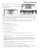
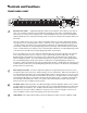
Safety Instructions Caution: To reduce the hazard of electrical shock, do not remove cover or back. No user serviceable parts inside. Please refer all servicing to qualified personnel. WARNING: To reduce the risk of fire or electric shock, do not expose this unit to rain or moisture.
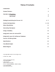
Table of Contents Introduction 2 System Features 3 Controls and Functions Front Panel Rear Panel 4 5 Setting Up and Using the S curve 131 System Configurations 6-7 8 - 10 About Equalization 11 Grounding Techniques 12 Using a Patchbay 12 Using the S curve 131 with an RTA 13 Using the S curve 131 to Remove Feedback 14 S curve 131 Wiring Guide 15 Specifications 16 Pass-Band Graphs 16 Block Diagram 17 Copyright 2003, Samson Technologies Corp.
Introduction Congratulations on purchasing the Samson S curve 131 1/3 Octave, single channel, 31 Band Constant Q Graphic Equalizer! Although this product is designed for easy operation, we suggest you take some time out first to go through these pages so you can fully understand how we’ve implemented a number of unique features. The S curve 131 is a professional quality signal processor that gives you precise tonal control over a mono audio signal.
S curve 131 Features The Samson S curve 131 Graphic Equalizer utilizes state-of-the-art, Constant Q filtering technology for precise tonal control. Here are some of it’s main features: • The S curve 131 has 31 bands of equalization, with each frequency band representing 1/3 of an octave in the 20 Hz to 20 kHz range. • Constant Q circuitry ensures that the bandwidth of the selected frequency area stays the same even when approaching maximum boost or attenuation.
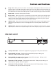
Controls and Functions FRONT PANEL LAYOUT 1 Equalizer level sliders - Independent Equalizer sliders are provided for each frequency area (The S curve 131 provides 31 frequency areas).Calibration markings on either side of each Equalizer slider allow you to cut or boost each frequency area. As described below, the exact action of the Equalizer sliders depends upon the setting of the Range switch as well as the setting of the Cut Only switch (see #3 and #5.
Controls and Functions 5 Range switch - When pressed in, the LED in the switch lights and the Equalizer sliders cut or boost each frequency area by up to 6 dB, allowing fine frequency curves to be set. When out (in the up position), the Equalizer sliders cut or boost each frequency area by up to 12 dB, allowing course control. The setting of the ±12dB switch also affects how Cut Only operates—see #3 on the previous page for more information. 6 Power switch - Use this to turn the power on and off.
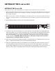
SETTING UP THE S curve 131 SETTING UP THE S curve 131 Setting up your S curve 131 Graphic Equalizer is a simple procedure which takes only a few minutes: 1. Remove all packing materials (save them in case of need for future service) and decide where the unit is to be physically placed—it can be used free-standing or mounted in a standard 19" rack (The S curve 131 requires only a single rack space). 2. Make sure the power to all mixers and amplifiers in your audio system is off.
SETTING UP THE S curve 131 7. Press the front panel Power switch in order to turn on the S curve 131. Press the Bypass switches in to activate the equalizer. Note that audio signal will be muted for approximately five seconds until the relay power-on circuitry is activated (at which time you’ll hear a click and the audio signal will be unmuted). 8. Apply an input signal to the S curve 131 (if sending signal from a mixer output bus, drive the mixer’s output meters at approximately 0 VU).
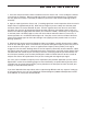
S curve 131 System Configurations Using the S curve 131 with Active Speakers In this example the mixer’s mono output is connected to the S curve 131’s input. Then, the S curve 131’s output is connected to the input of the first active (self-powered) loudspeaker. The second loudspeaker is connected to the first using the first loudspeaker’s extension output. Using the S curve 131 with Passive Speakers In this example the mixer’s mono output is connected to the S curve 131’s input.
S curve 131 System Configurations Using the S curve 131 in Insert Points You can use the S curve 131 in your mixer’s insert points if you want to equalize a mono channel, individually in the mix. In this example the S curve 131’s Channel 1 INPUT and OUTPUT are inserted on a bass guitar channel using a 1/4-inch TRS to 2 x 1/4-inch TS “Y” cable. For more information on cable wiring see the S Curve 131 Wiring Guide page 15 in this manual.
In this example two S curve 131’s are used for the stereo main and for the 2-channel monitor mix. The mixer’s left and right outputs are connected to the first pair of S curve 131’s inputs for the main PA speakers. Then, the outputs are connected to the inputs of the active (self-powered) loudspeakers. For the monitor mix, the mixer’s AUX1 output is connected to the third S curve 131 and AUX2 output is connected to the fourth S curve 131’s input.
About Equalization The S curve 131 gives you fine control over shaping a sound, using a process called equalization. But there are few areas of sound engineering more misunderstood than equalization, and, just as good EQ can really help a sound, bad EQ can really hurt it, so read on... Every naturally occurring sound consists of a broad range of pitches, or frequencies, combined together in a unique way. This blend is what gives every sound its distinctive tonal color.
Grounding Techniques Hum and buzz are the biggest enemies you face when interconnecting a large number of different pieces of equipment to one another.
Using the S curve 131 with an RTA An RTA (Real Time Analyzer) is a device which measures the relative levels of multiple frequency areas. This device, in conjunction with a pink noise generator, is the perfect companion for your S curve 131. Together with a high quality microphone, these tools allow you to fine tune the overall frequency response of your audio system in any given environment (this procedure is sometimes known as “tuning” a room).
Using the S curve 131 to Remove Feedback One of the most important applications for the S curve 131 is removing feedback from an onstage monitor system. This procedure is sometimes called “ringing out,” since feedback usually begins with a slight ringing sound at the resonant frequencies where the loop between microphone and speaker is loudest.
S curve 231 Wiring Guide S curve 131 Wiring Guide There are several ways to interface the S curve 131, depending on your exact monitoring set-up. Follow the cable diagrams below for connecting your monitor system.
Specifications 1: Center frequencies (Hz) 20, 25, 31.5, 40, 50, 63, 80, 100, 125, 160, 200, 250, 315, 400, 500, 630, 800, 1 k, 1.25 k, 1.6 k, 2 k, 2.5 k, 3.15 k, 4 k, 5 k, 6.3 k, 8 k, 10 k, 12.5 k, 16 k, 20 k 2: Variable range ±6 dB or ±12 dB 3: Frequency response (unity) <10 Hz to 90 kHz ±3 dB 4: THD+N, unity gain (20Hz to 20kHz) Less than 0.01% 5: Main level Max.
S curve 131 Block Diagram 17
Samson Technologies Corp. 575 Underhill Blvd. P.O. Box 9031 Syosset, NY 11791-9031 Phone: 1-800-3-SAMSON (1-800-372-6766) Fax: 516-364-3888 www.samsontech.