-6 0 +6 CHANNEL LEVEL dB CLIP -30 -24 -18 -12 -6 -3 0 MUTE / ON ST / 2CH 0 OFF AUX 10MAIN HF AUX IN -3 0 0 VOLUME 0 HF MAIN PHONES AUX IN -3 0 0 VOLUME 0 HF MAIN PHONES AUX IN -3 0 CHANNEL 4 CLIP 0 VOLUME ST / 2CH 0 HF MAIN PHONES AUX IN HEADPHONE MIXER/AMP 0 VOLUME 10 8 12 R PAN 12 4 8 L AUX POWER 8 4 12 LF 5 4 8 12 10 8 12 R PAN 12 MUTE / ON 4 8 L AUX -6 4 8 4 12 LF -30 -24 -18 -12 5 4 8 12 10 CHANNEL LEVEL dB CHANNEL 3 CLIP
Safety Instructions Caution: To reduce the hazard of electrical shock, do not remove cover or back. No user serviceable parts inside. Please refer all servicing to qualified personnel.
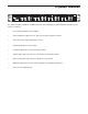
Table of Contents Introduction 2 S•phone Features 3 Controls and Functions Front Panel Layout Rear Panel Layout 4-5 Operating the S•phone Setting Up the S•phone S•phone Master section S•phone Channels Stereo and Two Channel Modes 6-7 7 8 9 S•phone Connections Cue Mix Set-up for Multitrack Vocal Recording Cue Mix Set-up for Multitrack Rhythm section Recording Linking Multiple S•phones Headphone Impedance and Sensitivity ratings 10 11 12 13 S•phone Wiring Guide 14 Specifications 15-16 Block Diag
Introduction Congratulations on purchasing the Samson S•phone Headphone Amplifier! Although this unit is designed for easy operation, we suggest you take some time out first to go through these pages so you can fully understand how we’ve implemented a number of unique features. The S•phone is a compact, high-quality device that allows you to monitor any stereo or monophonic source signal (balanced or unbalanced) over as many as twelve separate headphones.
S•phone Features MASTER LEVEL dB -30 -24 -18 -12 -6 0 +6 CHANNEL LEVEL dB CLIP -30 -24 -18 -12 -6 -3 0 MUTE / ON ST / 2CH 0 10MAIN HF INJECT AUX IN 0 12 MUTE / ON 0 VOLUME 0 8 HF L MAIN PHONES AUX IN 0 MUTE / ON 12 0 0 VOLUME HF L MAIN PHONES AUX IN -3 0 CHANNEL 4 CLIP 0 VOLUME ST / 2CH 0 HF L MAIN PHONES AUX IN 0 VOLUME 10 8 12 R PAN 12 4 8 AUX POWER 8 4 12 LF 5 4 8 12 10 8 12 R PAN 12 MUTE / ON 4 4 AUX -6 4 8 8 12 LF -30 -24 -
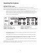
Controls and Functions FRONT PANEL LAYOUT 2 1 3 4 MASTER LEVEL dB -30 -24 -18 -12 -6 0 CHANNEL LEVEL dB +6 CLIP -30 -24 -18 -12 -6 -3 0 0 MUTE / ON ST / 2CH 10MAIN INJECT 9 10 11 12 13 15 16 1 MASTER LEVEL METER - Indicates the amount of signal being driven into the four channels from the master volume control. 2 MASTER VOLUME - Controls the level being sent to the individual channels. 3 CHANNEL LEVEL METER - Displays the amount of power being supplied to the channels.
Controls and Functions 5 CHANNEL LEVEL dB -30 -24 -18 -12 -6 -3 0 E ST / 2CH 0 8 PHONES -6 -3 HF 12 4 4 12 12 MUTE / ON 0 VOLUME CLIP ST / 2CH 0 LF AUX IN AUX PAN MAIN PHONES POWER 8 HF 12 4 4 12 12 8 R 5 4 8 12 10 8 L 8 CHANNEL 4 0 4 8 8 R -30 -24 -18 -12 5 4 12 10 MAIN CHANNEL LEVEL dB CHANNEL 3 CLIP 4 MUTE / ON 7 6 0 VOLUME 10 8 LF AUX IN R L AUX PAN MAIN 11 HEADPHONE OUTPUT - A front panel headphone output for each channel.
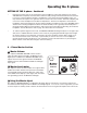
Operating the S•phone SETTING UP THE S•phone Setting up your S•phone Headphone Amplifier is a simple procedure, which takes only a few minutes. Remove all packing materials (save them in case of need for future service) and plug the provided AC power cord in the rear AC inlet, but don’t plug the power cable into a wall outlet just yet. • Connect the output from the device you want monitored to the Left/Right MAIN INPUT jacks on the S•phone rear panel.
Operating the S•phone SETTING UP THE S•phone - Continued • Repeat the previous step for all Channels that have headphones connected, making sure to start the VOLUME knob completely counterclockwise and then slowly raising it until the desired level is achieved. If you have connected different models of headphones to the various Channel Headphone jacks, you may find that some require more gain than others to achieve the same volume.
Operating the S•phone S • PHONE CHANNELS 1 Headphone Output The S•phone’s Headphone Output jack accepts a standard 1/4” TRS connector for easy interface with most professional headphones. Once the MASTER VOLUME has been set, the channels output level is set by the VOLUME knob. CHANNEL LEVEL dB -30 -24 -18 -12 -6 -3 0 8 CHANNEL 1 CLIP 0 4 MUTE / ON 2 ST / 2CH 3 8 8 12 HF 4 2 Channel MUTE Switch The S•phone features Mutes Switches on each of the four channels.
Operating the S•phone STEREO AND TWO-CHANNEL MODES Each of the S•phone’s four channels can be set to operate in two different modes: Stereo and 2 Channel. Stereo Mode Stereo mode is a normal operating mode where all mix inputs including MAIN, MASTER INJECT, as well as the Channel AUX input, maintain their stereo image throughout the signal path to each headphone output. The individual Channel’s PAN control is used to adjust the balance between the Left and Right side.
HEADPHONE MIXER/AMP INJECT -30 -24 -18 -12 0 5 +6 10MAIN CLIP MASTER VOLUME OFF AUX -6 MASTER LEVEL dB TO LEFT AND RIGHT MAIN INPUT ON REAR PANEL 10 -6 0 AUX IN SA M SO CLIP ST / 2CH -3 N 4 4 12 8 12 8 21 R SIGNAL FLOW Lead Vocal PHONES MUTE / ON -30 -24 -18 -12 CHANNEL LEVEL dB RIGHT MAIN INPUT LEFT LF HF 8 8 12 4 12 4 AUX L 0 5 PAN VOLUME CHANNEL 1 0 MAIN R 10 0 CLIP 4 LF HF 8 8 12 4 12 4 AUX L 0 5 PAN VOLUME CHANNEL 2 0 MAIN R 10
HEADPHONE MIXER/AMP INJECT -30 -24 -18 -12 0 +6 5 10MAIN CLIP MASTER VOLUME OFF AUX -6 MASTER LEVEL dB TO LEFT AND RIGHT MAIN INPUT ON REAR PANEL -6 0 CLIP AUX IN ST / 2CH -3 SIGNAL FLOW 11 4 12 8 12 8 4 LF HF 8 8 12 4 12 4 AUX L 0 5 PAN VOLUME CHANNEL 1 0 Rhythm Guitar PHONES MUTE / ON -30 -24 -18 -12 CHANNEL LEVEL dB RIGHT MAIN INPUT LEFT MAIN R 10 0 CLIP AUX IN ST / 2CH -3 SIGNAL FLOW 4 12 8 12 8 4 LF HF 8 8 AUX L 0 PAN VOLUME 5 MAI
S•phone Connections LINKING MULTIPLE S•phones Any number of S•phones’ can be linked together (daisy-chained), allowing you to monitor an input signal over more than twelve sets of headphones, or to give individual musicians more control over their own headphone mix. To do this, simply follow these basic steps: • Make a connection between one S•phone’s Left/Right Link outputs and the next one’s Left/Right Main inputs.
S•phone Connections Headphone Impedance and Sensitivity Ratings Virtually all headphones that terminate in a stereo 1/4" plug can be used with the S•phone Headphone Amplifier. This chart provides a partial listing of some of the more popular models, along with their impedance and sensitivity ratings.
S•phone Wiring Guide Unbalanced 1/4” Connector Signal Signal Ground Ground Tip (signal) Sleeve (ground) Balanced TRS 1/4” Connector Signal (ring) Tip (signal) Ring (signal) Signal (tip) Signal (tip) Signal (ring) Ground Ground Sleeve (ground) Sleeve (ground) Insert Cable 1/4” TRS connector to two 1/4” can be used to connect a stereo signal to the Channel AUX or Master Inject.
Specifications Master Section (Rear Panel) Input Impedance Max. input level CMRR: 2 TRS Balanced 1/4" (Left-Right) or (Left mono) 15 k Ohms balanced +26 dBu balanced Min 40dB, >55 dB @ 1 kHz Master Section (Front Panel) Master Volume control Master Level Meters Master Inject 0 - 10 5 Segment LED (–30 to Clip) 1/4" TRS jack (Left-Right) Link Output Connectors Max Output Level 2-1/4" TRS Balanced (Left-Right) Parallel to Main Input Matches Main Input Channels AUX IN Connectors Impedance Max.
16 HEADPHONE OUTPUT CH STEREO AUX IN MASTER 2CH AUX IN RIGHT BALANCED OUTPUTS LEFT RIGHT BALANCED INPUTS LEFT (MONO) FRONT PANEL JACKS REAR PANEL JACKS LOGIC SENSOR MAIN INPUT VOLUME ∑ ∑ MASTER LEVEL METER HIGH 2 BAND EQ +12 / -12dB LOW RING RIGHT LEFT PHONES COLD RING LOGIC CONTROL LEFT / RIGHT BALANCE AUX / MAIN BLEND GND SLEEVE GND SLEEVE INPUT/OUTPUT TIP HOT TIP C O N N E C T I O N S BALANCE AUX (L) MAIN(R) HIGH 2 BAND EQ +12 / -12dB LOW ST / 2CH CH VOLUME MUTE CH
Samson Technologies Corp. 575 Underhill Blvd. P.O. Box 9031 Syosset, NY 11791-9031 Phone: 1-800-3-SAMSON (1-800-372-6766) Fax: 516-364-3888 www.samsontech.