0-Channel Rack Mount Line Mixer Owner’s Manual www.samsontech.
Important Safety Information AVIS RISQUE DE CHOC ÉLECTRONIQUE NE PAS OUVRIR CAUTION: TO REDUCE THE RISK OF ELECTRIC SHOCK, DO NOT REMOVE COVER (OR BACK). NO USER-SERVICEABLE PARTS INSIDE. REFER SERVICING TO QUALIFIED SERVICE PERSONNEL. This lightning flash with arrowhead symbol within an equilateral triangle is intended to alert the user to the presence of non-insulated “dangerous voltage” within the product’s enclosure that may be of sufficient magnitude to constitute a risk of electric shock.
Important Safety Information 1. Read these instructions. 2. Keep these instructions. 3. Heed all warnings. 4. Follow all instructions. 5. This apparatus shall not be exposed to dripping or splashing liquid and no object filled with liquid, such as a vase, should be placed on the apparatus. 6. Clean only with a dry cloth. 7. Do not block any of the ventilation openings. Install in accordance with the manufacturer's instructions. 8. 9.
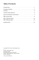
Table of Contents Introduction . . . . . . . . . . . . . . . . . . . . . . . . . . . . . . . . . 1 Package Contents . . . . . . . . . . . . . . . . . . . . . . . . . . . . . 2 Features . . . . . . . . . . . . . . . . . . . . . . . . . . . . . . . . . . . 3 Controls and Functions . . . . . . . . . . . . . . . . . . . . . . . . . . 4 Input and Output Connections . . . . . . . . . .
Introduction The Samson SM10 rack mount mixer is a versatile tool for many sound applications. The SM10 mixer features eight independent stereo line input channels, and includes two channels with XLR microphone preamps. There are also two additional line inputs with stereo 1/4” jacks and level controls that can be used to daisy-chain SM10 mixers together. The SM10 features a multitude of signal routing options, with Monitor (Pre-Fade), EFX (Post-Fade), and Mix B sends on Channels 1-8.
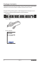
Package Contents Unpack the carton and check for all parts shown. Save the carton and packing material in case you ever move or need to send the units for service. If any part of the product appears to be damaged, do not attempt to use it. Contact your authorized Samson dealer or local distributor.
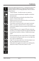
Features The Samson SM10 rack mount mixer is a comprehensive all-in-one solution for fixed installation, live sound, on-stage monitoring, keyboard submixer and recording applications. Here are some of its main features: • 10 input channels – Two Mic/Line plus ten stereo line • Low noise, discrete microphone pre-amplifiers with 48-Volt phantom power. • Versatile signal routing via Main Mix, Mix B, Mon, EFX bus outputs, as well as mono output.
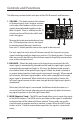
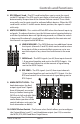
Controls and Functions The following section details each part of the SM10 controls and functions. 1. VOLUME – This knob controls the volume of channel inputs and is used to continuously adjust the loudness of the various signals being blended together at the Main Outputs. There is a detent at the 12 o’clock position of the knob, which indicates unity gain. 1 Moving the knob counterclockwise from the 12 o’clock position causes the signal 3 to be attenuated.
Controls and Functions 4. E FX (Effects) Send – The EFX send knob allows you to route the signal to the EFX outputs. The EFX send is post-fader so the level of the signal is determined by the position of the channel Volume control. These sends are usually used to route signal to outboard effects devices. When the EFX send knob is at the 12 o’clock center detent position, the signal is routed with unity. 5. M UTE/CLIP/MIX B – This switch will flash RED when the channel input signal peaks.
Controls and Functions 11. O utput Meter – This six-segment meter shows the continuous output level of the Main Mix, MON, EFX, or MIX B, depending on the position of the SOURCE select switch (see #10). For optimum signal-to-noise ratio, adjust all levels so that program material is usually at or around 0 VU, with occasional, but not steady, excursions to the red segments. 12. M ON OUT LEVEL – The SM10 provides a second MON output connector carrying a mono signal of the MON mix.
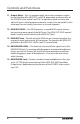
8 10 14 15 Input and Output Connections 18 16. M ic/Line Inputs (channels 1 and 2) - Use these Combo XLR plus 1/4inch jacks to connect a microphone or line level signal to channels 1 and 2. The XLR inputs provide 48-volt phantom power for use with condenser microphones. 6 17 16 17. L ine Inputs - Use these balanced 1/4” jacks to connect line level sources such as synthesizers, drum machines, MP3 players, or effects processors to any of the 8 channels.
3 4 Input and Output Connections 25 24 22. M AIN OUTPUTS 1/4-inch Jacks - In live performance applications, these outputs 1can be2used to 5 connect the SM10 to a power amp and speakers. In recording applications, these outputs are used to connect to a stereo device such as computer sound card, MP3, or hard disk recorder. The signals at the Main Outputs jacks follow the Main Output level controls. 23 22 23.
SM10 Quick Start The following section explains the basic operation of the SM10. CONNECTING MICROPHONES AND INSTRUMENTS 1. R emove all packing materials (save them in case of need for future service) and decide where the unit is to be physically placed—it can be mounted in any standard 19” rack (requiring one rack space), or used on a tabletop. 2. B efore connecting mics or instruments, make sure that the power to all your systems components, including the SM10, are turned off.
SM10 Quick Start SENDING AN INDEPENDENT MIX TO THE MONITOR SPEAKERS The SM10’s MON auxiliary send can be used to feed a separate set of amplifiers and loudspeakers for stage monitors. This lets you build one stereo mix for the main mix, or amplifiers and speakers facing the audience, and another stereo mix for the amplifiers and monitor speakers facing the musicians. 1. R aise the MON controls for the channels that you wish to hear from the monitor speakers.
SM10 Quick Start USING AN EXTERNAL EFFECT If you prefer to use an external device for effects processing, you can easily connect the unit using the SM10 EFX bus. Follow the simple steps below to interface your processor: 1. Connect the EFX OUTPUT to the input of the external effect processor. 2. Connect the outputs of the effects processor to channel 9 stereo line input. 3. Set the EFX SEND control to the 12 o’clock position. 4.
SM10 System Setup SIGNAL FLOW SIGNAL FLOW SIGNAL FLOW SIGNAL FLOW SIGNAL FLOW SIGNAL FLOW SIGNAL FLOW SIGNAL FLOW 12 SM10
SM10 Wiring Guide CONNECTING THE SM10 There are several ways to interface the SM10 to support a variety of applications. The SM10 features balanced inputs and outputs, so connecting balanced and unbalanced signals is possible.
Specifications Inputs Microphone XLR balanced (2) Line 1/4” TRS balanced (Ch 1-8), 1/4” stereo (Ch 9-10) Input Impedance Mic 1.
Notes 45 Gilpin Avenue Hauppauge, New York 11788-8816 Phone: 1-800-3-SAMSON (1-800-372-6766) Fax: 631-784-2201 www.samsontech.