
User Manual


AirLine AH7 Wireless System 5
ENGLISHFRANÇAISDEUTSCHEESPAÑOLITALIANO
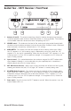
1. Antennas (A and B) - The antenna mountings allow full rotation for optimum placement.
In normal operation, both antennas should be placed in a vertical position. The antennas
can be folded inward for convenience when transporting the CR77.
2. VOLUME control - This knob sets the level of the audio signal being output through both
the balanced and unbalanced output jacks on the rear panel. Reference level is obtained
when the knob is turned fully clockwise (to its “10” setting).
3. AUDIO METER - This display indicates the strength of the incoming audio signal. When
the “0” segment is lit, the incoming signal is optimized at unity gain; when the “+6”
segment is lit, the signal is overloading. When only the left-most “-20” segment is lit, the
incoming signal is at just 10% of optimum strength. If no segments are lit, little or no
signal is being received.
4. Squelch control - This control determines the maximum range of the CR77 before audio
signal dropout. Although it can be adjusted using the supplied plastic screwdriver, it
should normally be left at its factory setting.
5. ANT. A/B Antenna Indicators - When signal is being received, one of these will be lit green,
showing you whether the (left) “A” or (right) “B” antenna is currently being used.
6. RF METER (Radio Frequency) - This display indicates the strength of the incoming radio
signal. When the “100%” segment is lit, the incoming RF signal is fully modulated and
at optimum strength. When only the second most left-most “10%” segment is lit, the
incoming signal is at just 10% of optimum strength. If no segments are lit, little or no
signal is being received.
7. Power switch - Use this to turn the CR77 power on and off. When the receiver is on, the
internal Power LED is lit.
Guided Tour - CR77 Receiver / Front Panel
ANT. A
ANT. B
VOLUME
POWER
RF METERAUDIO METER dB
0 10 25 50 75 1000 +3 +6-5-10-20
ANT. A ANT. B
SQUELCH
MIN
CR77 UHF TRUE DIVERSITY RECEIVER
MAX
1
2
3
4
5
5
1
7
6