MDR Series Mixers TEN CHANNEL MIXER
Safety Instructions/Consignes de sécurité/Sicherheitsvorkehrungen/Instrucciones de seguridad WARNING: To reduce the risk of fire or electric shock, do not expose this unit to rain or moisture. To reduce the hazard of electrical shock, do not remove cover or back. No user serviceable parts inside. Please refer all servicing to qualified personnel.
Table of Contents Introduction 2 MDR1064 Features 3 Front and Rear Panel Layout 4 Front and Rear Panel Controls 5 Controls and Functions Mono/Stereo Input Channel Section Master Section 6–7 8–9 MDR1064 Input and Output Connections 10–11 Operating the MDR1064 12–14 System Set-ups 15–16 MDR1064 Wiring Guide 17 Specifications 18 Block Diagram 19 Notes 20 Copyright 2004, Samson Technologies Corp. Printed February, 2004 Samson Technologies Corp. 575 Underhill Blvd. P.O.
Introduction Congratulations on your purchase of the Samson MDR1064 mixer! The MDR1064 is a ten-channel mixer, with six low noise microphone pre-amps. The six Mic/line inputs and two stereo inputs each feature a 3-band equalizer plus two Aux sends. The MDR1064’s master section includes two stereo Aux returns and a 2-tack Input and Output for playing back stereo devices and for recording your mix.
MDR1064 Features The Samson MDR1064, ten-channel mixer is a comprehensive, all-in-one solution for live sound, recording, fixed installation and post production applications. Here are some of its main features: • Eight Channels – Six Mic/Line plus two Stereo inputs with mic pre’s. • Flexible design topology ideal for live sound, recording and post production. • 2 Track Input and Output allows you to connect a CD, DAT, Cassette, Mini Disk or Computer Sound Card.
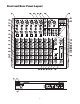
Front and Rear Panel Layout 4
Front and Rear Panel Controls 20 AUX SEND 1 – Line level output from the Auxiliary 1 bus. FRONT PANEL 1 MIC IN – Input connector for Low-Noise Microphone preamp. 2 LINE IN–Input connector for Line level inputs. 3 INSERT – 1/-4-inch TRS (TIP/RING/SLEEVE) connector providing send and recieve channel patch point for outboard effects. 4 GAIN – Used to set the input level of the mic pre and line input. 5 LOW CUT – Bass roll off switch at 75Hz used to eliminate unwanted low end rumble and hum.
Controls and Functions MONO/STEREO INPUT CHANNEL SECTION The following section details each part of the MDR1064’s MONO INPUT CHANNELS including the GAIN control, LOW CUT switch, 3-BAND EQ, AUX sends, PEAK LED, PAN and LEVEL controls. The input channels one through six on the MDR1064 feature high quality, discrete transistor pre-amp providing transparency and extended dynamic range.
Controls and Functions (MONO/STEREO INPUT CHANNEL CONTINUED) NOTE: The channel’s AUX 2 signal is sent to the AUX 2 bus from a location in the signal path after the channel’s LEVEL control. This is commonly referred to as a POST FADER send. This means that the amount of signal that is sent to the AUX 2 bus will be affected not only by the setting of the AUX 2 knob control, but it will also be affected by the setting of the LEVEL control.
Controls and Functions MASTER SECTION 10 MAIN LEVEL The master MAIN control is the overall volume control for the left and right mix bus. These line level signals are output from the MAIN MIX jacks. 11 PHONES / CR The PHONES / CR control is used to set the level sent to the control room outputs, and also to the headphone jack.
Controls and Functions MASTER SECTION (continued) 15 AUX RET 2 The AUX RETURN 2 adjusts the level of the signal present at the AUX 2 RET jacks. This signal is summed, or mixed in to the main L/R MIX bus. 16 TO AUX 1 This routes the signal that is present on the AUX 2 RETURN jacks to AUX 1 so that the effects can be heard in the monitor mix. 17 POWER LED The Power LED lights up to indicate that the main POWER switch (located on the rear panel) is on.
MDR1064 Input and Output Connections CHANNEL 1 – 6 MIC and LINE INPUTS The MDR1064’s channel 1 through 6 mono inputs each have a 1/4-inch connector for line level signals and XLR connectors for the MIC signals. Channels 7/8 and 9/10 stereo inputs each have 1/4-inch connectors for line level inputs. By using the GAIN control on channels 1 through 6, you can connect a variety of signal sources from microphones to line level devices such as synthesizers, and drum machines.
MDR1064 Input and Output Connections 5 MAIN MIX LEFT/RIGHT XLR OUTPUTS In a live sound application, the LEFT/ RIGHT MIX outputs are connected to a power amplifier or powered speakers. In a recording application, the LEFT/ RIGHT MIX outputs are used to connect to the inputs of a stereo device such as 5 computer sound card, DAT, or cassette recorder. 6 7 MAIN MIX LEFT/RIGHT 1/4-INCH OUTPUTS In a live sound application, the LEFT/ RIGHT MIX outputs are connected to a power amplifier or powered speakers.
Operating the MDR1064 BASIC OPERATION The following section explains the basic operation of the MDR1064. CONNECTING MICROPHONES AND INSTRUMENTS 1. Before connecting mics or instruments, make sure that the power of all your systems components including the MDR1064 is turned off. Also, make sure that the MAIN LEVEL and PHONES / CR controls are turned all the way down. 2.
Operating the MDR1064 SENDING AN INDEPENDENT MIX TO THE MONITOR SPEAKERS The MDR1064’s AUX1 auxiliary send can be used to feed a separate set of amplifiers and loudspeakers for stage monitors. This lets you build one mono mix for the amplifiers and monitor speakers facing the musicians, and the other stereo mix for the amplifiers and speakers facing the audience. 1. Raise the AUX1/MON controls for the channels that you wish to hear from the monitor speakers.
Operating the MDR1064 USING AN EXTERNAL EFFECT If you prefer to use an external device for effects processing, you can easily connect the unit using the MDR1064 AUX 2 bus. Follow the simple steps below to interface your processor: 1. Connect the AUX 2 OUTPUT to the input of the external effect processor. 2. Connect the outputs of the effect processor to the AUX 2 RETURN located on the MDR1064’s master section. 3. Set the MAIN LEVEL control to the "5" position. 4.
This system shows the MDR1064 connected to a pair of powered speakers like the SAMSON Expedition EX20. The AUX SEND 1 output is connected to an external power amp, which is driving 2 monitor speakers. For inputs, two microphones are connected to channels 1 and 2’s low-impedance inputs, and the output of the Bass Direct Box is also connected to the lowimpedance input on channel 4. The Keyboards, as well as the Lead and Rhythm Guitar signal processor's’ outputs, are connected to the MDR1064’s line inputs.
This system shows the MDR1064 in a recording set up with the LEFT and RIGHT CONTROL ROOM output hooked up to powered studio monitors and the AUX 1 feed headphone mix sent to a Samson S phone headphone amp. For inputs, two microphones are connected to channel 1 and 2’s lowimpedance inputs, and the output of the Bass Direct Box is also connected to the lowimpedance input on channel 4. The Keyboards, as well as the Lead and Rhythm Guitar signal processor's’ outputs, are connected to the MDR1064’s line inputs.
MDR1064 Wiring Guide CONNECTING THE MDR1064 The are several ways to interface the MDR1064 to support a variety of applications. The MDR1064 features balanced inputs and outputs, so connecting balanced and unbalanced signals is possible.
MDR1064 Specifications Mono input channels Microphone input electronically balanced, discrete input configuration 10Hz to 45kHz (THD & N) 0.005% at 4dBu, 1kHz 0dB to +40dB (MIC) 105dB electronically balanced 10Hz to 45kHz 0.005% at 4dBu, 1kHz + -10dBu to +30dBu Frequency response Distortion Gain range SNR (Signal to Noise Ratio) Line input Frequency response Distortion (THD & N) Sensitivity range Stereo input Channels Line input Frequency response Distortion (THD & N) Balanced 10Hz to 45kHz 0.
MDR1064 Block Diagram 19
Notes 20
Samson Technologies Corp. 575 Underhill Blvd. P.O. Box 9031 Syosset, NY 11791-9031 Phone: 1-800-3-SAMSON (1-800-372-6766) Fax: 516-364-3888 www.samsontech.