Series M I C R O P R O C E S S O R T R U E D I V E R S I T Y WIRELESS SYSTEM AND Series WIRELESS SYSTEM OWNERS MANUAL ®
Table of Contents ENGLISH Introduction 3 Guided Tour - VR3TD Receiver Front Panel 5 Guided Tour - VR3TD Receiver Rear Panel 6 Guided Tour - VR3 Receiver Front Panel 7 Guided Tour - VR3 Receiver Rear Panel 8 Guided Tour - VT3L / VT3 Transmitter 9 Guided Tour - VH3 Transmitter 11 Setting Up and Using Your VHF TD Series / VHF Series System 12 Appendix A: VT3L Multipin Wiring Guide and Chart 51 Appendix B: Carrying Case 52 Specifications 53 FRANCAIS Introduction 15 Tour d'horizon - Façade avant du VR3TD 17 Tour
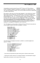
Introduction Every wireless system consists of at least two components—a transmitter and a receiver, both of which must be tuned to the same channel (that is, the same radio frequency) in order to operate correctly.* The Samson VHF TD Series or VHF Series system you have purchased operates in the 173.8 - 213.
ENGLISH Introduction The VR3 receiver provided with the VHF Series wireless system utilizes non-diversity technology, incorporating a single antenna for ease of use and minimal cost. The VR3TD receiver provided with the VHF TD Series system utilizes a patented technological breakthrough called “Microprocessor True Diversity,” whereby a single chassis houses two antennas (called “Antenna A” and “Antenna B”) and a receiver circuit.
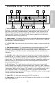
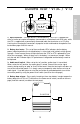
Guided Tour - VR3TD Front Panel 1 3 4 1 7 VOLUME SQL. 2 MIN. 10% 25% 75% 100% 125% ANT. B SAMSON VR3TD VHF TRUE DIVERSITY RECEIVER MAX. 5 6 5 OFF ON Series 8 1: Antennas (A and B) - The antenna mountings allow full rotation for optimum placement. In normal operation, both Antenna A (the antenna on the left) and Antenna B (the antenna on the right) should be placed in a vertical position. Both antennas can be folded inward for convenience when transporting the VR3TD.
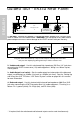
Guided Tour - VR3TD Rear Panel 2 AC CABLE LOCK ENGLISH 1 DC INPUT S. No. - CAUTION USE SAMSON AC ADAPTER ONLY LINE: -20dBm600Ω MIC: -40dBm600Ω CH : LINE MIC -10 dB 5KΩ BALANCED OUTPUT BALANCED SWITCH UNBALANCED OUTPUT + 4 3 Diversity Receiver XLR: ①GND ②HOT ③COLD POWER RATING F: DC 12V, 1.9W(160mA) CABLE LOCK LOOP THRU AND TIE 1: DC input - Connect the supplied 12 volt 250 mA power adapter here, using the strain relief as shown in the illustration below.
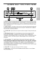
Guided Tour - VR3 Front Panel 1 3 6 4 VOLUME 10% SQL. 2 MIN. MAX. 25% 75% 100% VR3 VHF FM RECEIVER 125% SAMSON 5 OFF ON Series 7 1: Antenna - The antenna mounting allows full rotation for optimum placement. In normal operation, the antenna should be placed in a vertical position. It also can be folded inward for convenience when transporting the VR3.
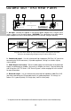
Guided Tour - VR3 Rear Panel 2 AC CABLE LOCK ENGLISH 1 DC INPUT 4 3 UNBALANCED OUTPUT - CAUTION USE SAMSON AC ADAPTER ONLY LINE: -20dBm600Ω MIC: -40dBm600Ω CH : MIC -10 dB 5KΩ BALANCED OUTPUT BALANCED SWITCH S. No. + LINE Non-Diversity Receiver XLR: ①GND ②HOT ③COLD POWER RATING F: DC 12V, 1.9W(160mA) CABLE LOCK LOOP THRU AND TIE 1: DC input - Connect the supplied 12 volt 250 mA power adapter here, using the strain relief as shown in the illustration below.
Guided Tour - VT3L / VT3 1 3 2 ENGLISH LOW MID HIGH ▲ BATTERY SAMSON AUDIO ON 1: Input connector - The input device is connected here. The VT3L is supplied with either a lavalier or headset microphone (connected via a Switchcraft mini-XLR jack), while the VT3 is supplied with a permanently connected cable that terminates at a 1/4" plug. A wiring chart showing the connections to popular lavalier and headset microphones can be found on page 49 of this manual.
INPUT VT3 SAMSON 6 5 GAIN POWER ▲ ENGLISH Guided Tour - VT3L / VT3 ON 7 SAMSON 8 5: Power on-off switch* - Use this to turn the VT3L / VT3 on or off (to conserve battery power, be sure to leave it off when not in use).
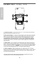
Guided Tour - VH3 1 CC LOW MID HIGH BATTERY LEVEL Ch2 X CCRVH3 ID ON ENGLISH OFF :XXXXXX DA XX NA xxx xxxx Tx CA BZ AUDIO F SAMSON 2 1: Audio on-off switch - When set to the “on” position, audio signal is transmitted. When set to the “off” position, the audio signal is muted. Because the carrier signal remains during muting, no “pop” or “thud” will be heard.
ENGLISH Setting Up and Using Your VHF TD Series/ VHF Series System The basic procedure for setting up and using your VHF TD Series or VHF Series Wireless System takes only a few minutes: 1. For the VHF TD Series / VHF Series system to work correctly, both the receiver and transmitter must be set to the same channel. Remove all packing materials (save them in case of need for future service) and check to make sure that the supplied receiver and transmitter are set to the same channel.
Setting Up and Using Your VHF TD Series/ VHF Series System VT 3L INPUT SAMSON VHF BELTPACK TRANSMITTER 10. If you hear distortion at the desired volume level (or if the “125%” segment LED in the AF Level meter is lighting frequently), first check that the VR3TD or VR3 rear panel Audio Output Level switch is set correctly. Next, make sure that the gain structure of your audio system is correctly set (consult the owners manual of your mixer and/or amplifier for details).
ENGLISH Setting Up and Using Your VHF TD Series/ VHF Series System 11. Conversely, if you hear a weak, noisy signal at the desired volume level (and with the Volume control of the receiver turned fully clockwise), again make sure that the VR3TD or VR3 rear panel Audio Output Level switch is set correctly and that the gain structure of your audio system is correctly set.
Introduction Merci d'avoir fait confiance au système sans fil VHF Samson VHF TD Series ou VHF Series ! Ces deux produits sont très simples d'emploi, mais nous vous conseillons tout de même de lire ces quelques pages pour tirer parti de tout leur potentiel. Un système sans fil est composé d'au moins deux éléments (émetteur et récepteur) qui doivent être réglés sur le même canal (sur la même haute fréquence) pour fonctionner correctement.
FRANCAIS Introduction Le récepteur VR3 du système sans fil VHF Series fait appel à la technologie non-diversity, incorpore une seule antenne pour une plus grande simplicité d'emploi et des coûts plus faibles. Le récepteur VR3TD du système VHF TD Series fait appel à une technologie brevetée du nom de True Diversity à microprocesseur, dans laquelle deux antennes (appelées "Antenne A" et "Antenne B") et un circuit de réception sont placés dans seul châssis.
Tour d'horizon - Façade avant du VR3TD 1 3 4 1 7 POWER ANT. A TX VOLUME SQL. 2 MIN. 10% 25% 75% 100% 125% ANT. B SAMSON VR3TD VHF TRUE DIVERSITY RECEIVER MAX. 5 6 5 OFF ON Series 8 2 : Potentiomètre de volume - Ce potentiomètre permet d'ajuster le niveau des signaux audio envoyés aux sorties symétrique et asymétrique de la façade arrière. Tournez-le au maximum vers la droite pour obtenir le niveau de référence.
Tour d'horizon - Façade arrière du VR3TD 2 AC CABLE LOCK 1 DC INPUT S. No. - CAUTION USE SAMSON AC ADAPTER ONLY LINE: -20dBm600Ω MIC: -40dBm600Ω CH : LINE MIC -10 dB 5KΩ BALANCED OUTPUT BALANCED SWITCH UNBALANCED OUTPUT + 4 3 Diversity Receiver XLR: ①GND ②HOT ③COLD POWER RATING F: DC 12V, 1.
Tour d'horizon - Façade avant du VR3 1 3 6 4 POWER TX VOLUME 10% SQL. 2 MIN. MAX. 25% 75% 100% VR3 VHF FM RECEIVER 5 125% SAMSON OFF ON Series 7 2 : Potentiomètre de volume - Ce potentiomètre permet d'ajuster le niveau des signaux audio envoyés aux sorties symétrique et asymétrique de la façade arrière. Tournez-le au maximum vers la droite pour obtenir le niveau de référence. 3 : Témoin "TXON" - S'allume lorsqu'un signal de porteuse suffisamment puissant est reçu par le VR3.
Tour d'horizon - Façade arrière du VR3 2 AC CABLE LOCK 1 DC INPUT 4 3 UNBALANCED OUTPUT - CAUTION USE SAMSON AC ADAPTER ONLY LINE: -20dBm600Ω MIC: -40dBm600Ω CH : MIC -10 dB 5KΩ BALANCED OUTPUT BALANCED SWITCH S. No. + LINE Non-Diversity Receiver XLR: ①GND ②HOT ③COLD POWER RATING F: DC 12V, 1.
Tour d'horizon - VT3L / VT3 1 3 2 LOW MID HIGH ▲ BATTERY SAMSON AUDIO ON 2 : Témoins d'usure de la pile - Ces trois diodes vous renseignent sur l'usure de la pile : la diode rouge s'allume lorsque la pile doit être changée, la diode jaune s'allume lorsque vous avez consommé la moitié de la pile et la diode verte s'allume lorsque la pile est neuve ou presque. Une de ces trois diode clignote lors de la mise sous tension du VT3L/VT3 (voir n°5 de la page suivante).
Tour d'horizon - VT3L / VT3 INPUT VT3 SAMSON 6 5 GAIN ▲ POWER ON 7 FRANCAIS SAMSON 8 5 : Interrupteur d'alimentation Power* - Il permet de mettre sous et hors tension les VT3L et VT3. Pour ne pas gaspiller inutilement la pile, veillez à bien mettre le VT3L/VT3 hors tension, position "off", lorsque vous ne l'utilisez pas.
Tour d'horizon - VH3 ON 1 CC LOW MID HIGH BATTERY LEVEL Ch2 X CCRVH3 ID OFF :XXXXXX DA XX NA xxx xxxx Tx CA BZ AUDIO SAMSON F 2 ON MIN MAX OFF POWER 23 LEVEL FRANCAIS 1 : Interrupteur Audio - Lorsqu'il est placé sur "on", les signaux audio sont transmis. Lorsqu'il est placé sur "off", la transmission est coupée. Comme le signal de porteuse reste actif lorsque la transmission est coupée, aucun bruit parasite n'apparaît.
Réglage et utilisation du système VHF TD Series / VHF Series La procédure de réglage de base des systèmes sans fil VHF TD Series ou VHF Series ne prend que quelques minutes. 1. Pour que les systèmes VHF TD Series / VHF Series fonctionnent correctement, il faut que le récepteur et l'émetteur soient réglés sur le même canal. Retirez l'emballage (gardez-le au cas où l'appareil nécessiterait une réparation) et vérifiez que l'émetteur et le récepteur sont réglés sur le même canal.
Réglage et utilisation du système VHF TD Series / VHF Series VT 3L INPUT SAMSON VHF BELTPACK TRANSMITTER 10. Si vous entendez de la distorsion au volume désiré (ou si le segment "125%" de l'afficheur de niveau audio s'allume fréquemment), commencez par vérifier si le sélecteur de niveau de sortie en façade arrière est placé sur la bonne position. Vérifiez ensuite le bon réglage du gain de votre système audio (consultez le manuel d'utilisation de votre amplificateur et/ou de votre mélangeur).
Réglage et utilisation du système VHF TD Series / VHF Series position et le bon réglage du gain de votre système audio. Si le problème persiste, voici quelques mesures à prendre : FRANCAIS • Si vous utilisez un émetteur VH3 ou VT3L relié à un microphone cravate ou serre-tête, son gain a été optimisé d'usine pour le modèle de microphone utilisé. Aucun réglage n'est donc nécessaire. Le problème est probablement dû à la trop grande distance séparant le microphone et la bouche. Rapprochez donc le microphone.
Einleitung Wir wollen Ihnen zum Erwerb des SAMSON VHF TD Series bzw. VHF Series Drahtlossystem gratulieren und uns herzlich bei Ihnen bedanken. Obwohl dieses Produkt auf einfache Handhabung ausgelegt ist, empfehlen wir Ihnen, sich diese Anleitung vor Inbetriebnahme zunächst sorgfältig und vollständig durchzulesen, damit Sie alle Eigenschaften dieses Gerätes verstehen und es so optimal nutzen können.
Einleitung DEUTSCHE Der dem VHF Series-System beiliegende Empfänger VR3 arbeitet auf der Basis der Non-Diversity Technology und verfügt nur über eine Antenne, was die Handhabung erleichtert und die Kosten reduziert. Das System VHF TD Series hingegen wird mit dem Empfänger VR3TD ausgeliefert und verwendet eine bahnbrechende und patentierte neuartige Technik, die als Microprocessor True Diversity bezeichnet wird.
Übersicht: VR3TD Vorderseite 1 3 4 1 7 POWER ANT. A TX VOLUME SQL. 2 MIN. 10% 25% 75% 100% 125% ANT. B SAMSON VR3TD VHF TRUE DIVERSITY RECEIVER MAX. 5 6 OFF ON Series 5 8 1. Antennen (A und B) - Die Antennenhalter haben einen Drehradius von 360°, um eine optimale Aufstellung zu erlauben. Bei normalem Betrieb sollten die beiden Antennen A (links) und B (rechts) senkrecht aufgestellt werden. Die Antennen lassen sich zum Transport des VR3TD einschieben.
Übersicht: VR3TD Rückseite 2 AC CABLE LOCK 1 DC INPUT S. No. - CAUTION USE SAMSON AC ADAPTER ONLY LINE: -20dBm600Ω MIC: -40dBm600Ω CH : LINE MIC -10 dB 5KΩ BALANCED OUTPUT BALANCED SWITCH UNBALANCED OUTPUT + 4 3 Diversity Receiver XLR: ①GND ②HOT ③COLD POWER RATING F: DC 12V, 1.9W(160mA) CABLE LOCK LOOP THRU AND TIE 1. Anschluß für das Netzteil - Schließen Sie hier das beiliegende Netzteil wie unten dargestellt an.
Übersicht: VR3 Vorderseite 1 3 6 4 POWER TX VOLUME 10% SQL. 2 MIN. MAX. 25% 75% 100% VR3 VHF FM RECEIVER 125% SAMSON OFF ON Series 5 7 1. Antenne - Der Antennenhalter hat einen Drehradius von 360°, um eine optimale Aufstellung zu erlauben. Bei normalem Betrieb sollte die Antenne senkrecht aufgestellt werden. Sie läßt sich zum Transport des VR3 einschieben.
Übersicht: VR3 Rückseite 2 AC CABLE LOCK 1 DC INPUT 4 3 UNBALANCED OUTPUT - CAUTION USE SAMSON AC ADAPTER ONLY LINE: -20dBm600Ω MIC: -40dBm600Ω CH : MIC -10 dB 5KΩ BALANCED OUTPUT BALANCED SWITCH S. No. + LINE Non-Diversity Receiver XLR: ①GND ②HOT ③COLD POWER RATING F: DC 12V, 1.9W(160mA) CABLE LOCK LOOP THRU AND TIE 1. Anschluß für das Netzteil - Schließen Sie hier das beiliegende Netzteil wie unten dargestellt an.
Übersicht - VT3L / VT3 1 3 2 LOW MID HIGH ▲ BATTERY SAMSON AUDIO ON 1. Audioeingang - Schließen Sie hier die Signalquelle an. Der VT3L wird entweder mit Kopfbügel- oder Ansteckmikrofon ausgeliefert, welches über den Mini-XLR-Anschluß mit dem Sender verbunden wird. Der VT3 dagegen verfügt über ein fest angeschlossenes Kabel mit Klinkenbuchse (6,35 mm). Ein Verbindungsdiagramm für verbreitete Ansteckund Kopfbügelmikrofone finden Sie auf Seite 49 in diesem Handbuch. 2.
Übersicht - VT3L / VT3 INPUT VT3 SAMSON 6 5 GAIN ▲ POWER ON 7 SAMSON 8 DEUTSCHE 5. Power-Schalter - Schalten Sie den Sender mit diesem Schalter ein und aus. Wenn Sie den Sender für längere Zeit nicht verwenden, schalten Sie den Schalter aus („Off“), um die Lebensdauer der eingelegten Batterie zu verlängern. 6. Gain-Regler - Dieser Regler bestimmt die Eingangsempfindlichkeit des Senders und wurde werksseitig optimal für das mitgelieferte Mikrofonmodell (VT3L) bzw.
Übersicht - VH3 ON 1 CC LOW MID HIGH BATTERY LEVEL Ch2 X CCRVH3 ID OFF :XXXXXX DA XX NA xxx xxxx Tx CA BZ AUDIO F SAMSON 2 1. Audio On/Off-Schalter - Wenn dieser Schalter in der Stellung „On“ steht, wird das Audiosignal gesendet. Steht der Schalter dagegen in der Einstellung „Off“, so wird das Signal nicht übertragen. Da jedoch das Trägersignal auch in der „Off“Stellung gesendet wird, werden beim Ein- und Ausschalten keine Nebengeräusche hörbar.
DEUTSCHE Aufbau und Betrieb des VHF TD Series / VHF Series Sie benötigen nur ein paar Minuten, um das VHF TD Series /VHF Series-System betriebsbereit zu machen. Gehen Sie wie folgt vor: 1. Damit das System korrekt arbeiten kann, ist es notwendig, daß der Sende/Empfangskanal von Sender und Empfänger übereinstimmen.
Aufbau und Betrieb des VHF TD Series / VHF Series VR3TD/VR3. Falls Sie den Sender VT3 mit einem angeschlossenen Instrument verwenden, spielen Sie nun dieses Instrument in gewohnter Weise und beobachten Sie dabei die AF Level-Anzeige am VR3TD/VR3. Wenn das „100%“-Segment dauerhaft und das darüber liegende nur gelegentlich leuchtet, ist der Audiopegel korrekt eingestellt.
Aufbau und Betrieb des VHF TD Series / VHF Series 11. Falls das Signal im Gegensatz zum vorher beschriebenen zu schwach sein sollte, obwohl der Volume-Regler am rechten Anschlag steht, überprüfen Sie auch hier zunächst, ob der Einstellschalter für den Ausgangspegel auf der Rückseite des VR3TD/VR3 und die Verstärkungseinstellungen Ihres Mischpults oder Verstärkers korrekt eingestellt sind.
Introducción ¡Muchas gracias por comprar el sistema inalámbrico Samson VHF TD Series o VHF Series! Aunque este aparato ha sido diseñado para ser muy sencillo de manejar, le recomendamos que pierda un poco de tiempo en leer estas páginas para así dominar totalmente las funciones que hemos incluido en él.
Introducción El receptor VR3 incluido en el sistema inalámbrico VHF Series utiliza tecnología de no diversificación, incorporando una sola antena para facilitar su uso y reducir los costes. El receptor VR3TD que viene en el sistema VHF TD Series utiliza un avance tecnológico patentado llamado “Microprocesador de Diversidad Real”, en el que una única carcasa alberga dos antenas (llamadas “Antena A” y “Antena B”) y un circuito receptor.
Recorrido Guiado - Panel frontal del VR3TD 1 3 4 1 7 POWER ANT. A TX VOLUME SQL. 2 MIN. 10% 25% 75% 100% 125% ANT. B SAMSON VR3TD VHF TRUE DIVERSITY RECEIVER MAX. 5 6 5 OFF ON Series 8 1: Antenas (A y B) - Los puntos de montaje de antena permiten una rotación total para conseguir una colocación óptima de las mismas. En su funcionamiento normal, tanto la antena A (la de la izquierda), como la antena B (la de la derecha) deberían estar colocadas en una posición vertical.
Recorrido Guiado - Panel trasero del VR3TD 2 AC CABLE LOCK 1 DC INPUT UNBALANCED OUTPUT - CAUTION USE SAMSON AC ADAPTER ONLY LINE: -20dBm600Ω MIC: -40dBm600Ω CH : LINE MIC -10 dB 5KΩ BALANCED OUTPUT BALANCED SWITCH S. No. + 4 3 Diversity Receiver XLR: ①GND ②HOT ③COLD POWER RATING F: DC 12V, 1.
Recorrido Guiado - Panel frontal del VR3 1 3 6 4 POWER TX VOLUME 10% SQL. 2 MIN. MAX. 25% 75% 100% VR3 VHF FM RECEIVER 5 125% SAMSON OFF ON Series 7 1: Antena - El punto de montaje de la antena le permite una rotación total para conseguir una colocación óptima de la misma. En su funcionamiento normal la antena debería estar colocada en una posición vertical. Esta antena es telescópica y puede ser recogida dentro de si misma para un mejor transporte del VR3.
Recorrido Guiado - Panel trasero del VR3 2 AC CABLE LOCK 1 DC INPUT 4 3 UNBALANCED OUTPUT - CAUTION USE SAMSON AC ADAPTER ONLY LINE: -20dBm600Ω MIC: -40dBm600Ω CH : MIC -10 dB 5KΩ BALANCED OUTPUT BALANCED SWITCH S. No. + LINE Non-Diversity Receiver XLR: ①GND ②HOT ③COLD POWER RATING F: DC 12V, 1.
Recorrido Guiado - VT3L / VT3 1 3 2 LOW MID HIGH ▲ BATTERY SAMSON AUDIO ON 1: Conector de entrada - Aquí se conecta la unidad de entrada. El VT3L viene con un micrófono lavalier o de diadema (conectado a través de un conector jack XLR mini de tipo Switchcraft), mientras que el VT3 viene con un cable conectado de forma permanente que termina en una clavija de 1/4”.
Recorrido Guiado - VT3L / VT3 INPUT VT3 SAMSON 6 5 GAIN ▲ POWER ON 7 SAMSON 8 5: Interruptor on-off de encendido* - Utilice este interruptor para encender o apagar el VT3L / VT3 (para mantener la pila durante más tiempo, asegúrese de dejar la unidad apagada cuando no la utilice).
Recorrido Guiado - VH3 ON 1 CC LOW MID HIGH BATTERY LEVEL Ch2 X CCRVH3 ID OFF :XXXXXX DA XX NA xxx xxxx Tx CA BZ AUDIO F SAMSON 2 1: Interruptor on-off de audio - Cuando se ajusta a la posición “on”, la señal audio es transmitida. Cuando se coloca en la posición “off”, la señal audio queda anulada. Dado que la señal portadora sigue activa durante la anulación de la otra, no se escuchará ningún “petardeo” o “chasquido”.
ESPANOL Ajuste y utilización de su sistema VHF TD Series / VHF Series El proceso básico de ajuste y utilización de su sistema VHF TD Series / VHF Series solo conlleva unos pocos minutos: 1. Para que el sistema VHF TD Series / VHF Series funcione correctamente, tanto el receptor como el emisor deberán estar ajustados al mismo canal.
Ajuste y utilización de su sistema VHF TD Series / VHF Series del mando de volumen del VR3TD o VR3 totalmente a la izquierda. Si está usando el transmisor VH3 o si está utilizando el transmisor VT3L con un micro de diadema o lavalier conectado, hable o cante en el micro a un nivel de ejecución normal a la vez que observa el medidor de nivel AF del panel frontal del VR3TD o VR3.
Ajuste y utilización de su sistema VHF TD Series / VHF Series 11. De forma opuesta, si escucha en la salida una señal ruidosa y débil al nivel de volumen que haya elegido (y con el control de volumen del receptor girado a tope a la derecha), asegúrese nuevamente de que la estructura de ganancia de su sistema de sonido haya ajustada correctamente.
Appendix A: VT3L Multipin Wiring Guide and Chart 1 2 3 4 SWITCHCRAFT TA3F MANUFACTURER AKG MODEL C410 PIN 1 PIN 2 PIN 3 SHIELD RED WHITE JUMP TO PIN 2 AUDIO TECHNICA AT831 YELLOW x 2 SHIELD RED x 2 JUMP TO PIN 2 AUDIO TECHNICA ATM75 YELLOW x 2 SHIELD RED x 2 JUMP TO PIN 2 ATPRO8HE YELLOW x 2 SHIELD N/C RED x 2 AUDIO TECHNICA ATPRO35X YELLOW x 2 SHIELD RED x 2 JUMP TO PIN 2 AUDIO TECHNICA MT350 SHIELD WHITE JUMP TO PIN 2 CM311(E) SHIELD WHITE RED JUMP TO PIN 2 SONY EC
Appendix B: Carrying Case SAMSON To ensure the longevity of your VHF TD Series / VHF Series system, and for convenience when on the road, your VHF TD Series / VHF Series system includes an impact-resistant polypropylene plastic carrying case with foam rubber padding. As shown in the illustration below, custom cutouts in the interior padding provide secure placement for all components in your system.
Specifications Transmitter / Emetteur / Sender / Transmisor (VT3L, VT3 and VH3): Transmission Mode Frequency Range Band A (European / UK models) Band B (European / UK models) OSC System RF Power Operating Range Frequency Stability Approvals Radiating Harmonic and Spurious Emission Antenna Type Audio Frequency Response Pre-Emphasis Noise Reduction System Signal To Noise Ratio Maximum Input Level T.H.D.
FCC Rules and Regulations Samson wireless systems are type accepted under FCC rules parts 90, 74 and 15. Licensing of Samson equipment is the user’s responsibility and licensability depends on the user’s classification, application and frequency selected. This device complies with RSS-210 of Industry & Science Canada.