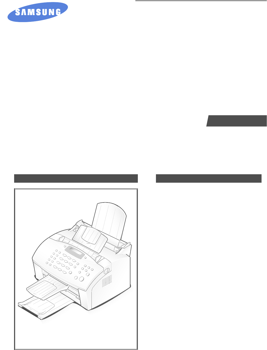
SAMSUNG FACSIMILE Msys5100P SF-5100/5100P SERVICE Manual FACSIMILE CONTENTS 1. Precautions 2. Specifications 3. Tech Mode 4. Disassembly and Reassembly 5. Maintenance & Troubleshooting 6. Exploded Views and Parts List 7. Electrical Parts List 8. Block Diagrams 9. Connection Diagrams 10. PCB Diagrams 11.
ELECTRONICS © Samsung Electronics Co.,Ltd. December 1999 Printed in Korea. VERSION NO. : 1.00 P/N.
1. Precautions Follow these safety, ESD, and servicing precautions to prevent personal injury and equipment damage. 1-1 Safety Precautions 1. Be sure that all built-in protective devices are in place. Restore any missing protective shields. 2. Make sure there are no cabinet openings through which people- particularly children- might insert fingers or objects and contact dangerous voltages. 3.
Precautions 1-2 ESD Precautions Certain semiconductor devices can be easily damaged by static electricity. Such components are commonly called “Electrostatically Sensitive (ES) Devices”, or ESDs. Examples of typical ESDs are: integrated circuits, some field effect transistors, and semiconductor “chip” components. The techniques outlined below should be followed to help reduce the incidence of component damage caused by static electricity.
2. Specification 2-1 Facsimile Machine type : Desk Top Applicable line : Public Switched Telephone Network (PSTN) or behind PABX Compatibility : ITU-T Group 3, ECM Data coding : MH/MR/MMR (ECM Mode) Modem speed : 14400/12000/9600/7200/4800/2400 bps Transmission speed : Approx. 6 sec. (V.M ECM:14.4 kbps) Effective scanning width : 8.3 inches (210 mm) Effective printing width : Letter : 8.
Specification 2-3 Printer Print Speed 6 PPM (Letter Size, 5% Charcter Pattern) Resolution 300 X 300 DPI Source of Light Laser Diode(LSU) Print Method Non-impact Electrophotography, Feed Method Multi-Purpose Feeder and Manual Feed Reference Center Reference Loading Paper Size At Copy Mode Laser Beam Bin Type Normal Paper : A4,Letter,Legal,B5, Executive, A5 Envelope : Normal Envelope Length : 149 ~ 365mm Width : 100 ~ 216mm Weight : For MPF, For Manual, Paper Capacity 60 ~163g/m 2 2 M
Specification Toner Cartridge One-Cartridge type Expected Life Span 50,000 Sheets Operating Environment Temperature : 10 ~ 32°C Humidity Storage Environment Temperature : -20 ~ 40°C Humidity Weight : 20 ~ 85% : 10 ~ 95%RH Net : Max. 7kg(with Accessory) Gross : Max. 14kg External Dimension 313(W) X 325(D) x 228(H)mm (without Handset) 376(W) X 361(D) x 336(H)mm (with Handset) Developer . Life Span : 5% Pattern,Min. 2,500/1,000 Sheets . Developing : Non-magnetic Contact Developing .
Specification 2-4 Quality Conditions Paper Normal Paper Environment Temperature : 20 ~ 25°C Humidity : 40 ~ 60% Print Quality Image Density Background Uniformity Fusing Start Position Skew Orthogonality Horizontal Scan Special Paper Exception Paper Jam Paper Curl Reliability Insulation Resistance Dielectric Strength Ground Continuity Voltage DIP AC Impulse Noise Leakage Current Surge OZONE Emission Top Cover Open Overcurrent Protect Fusing System Trouble Sensing Overheat Sensing 75g/m 2 Min. 1.
Specification 2-5 SMPS (Switching Mode Power Supply) Input (AC) AC Input Voltage Minimum Typical Maximum Max. AC Input Current Max. Inrush Current European 198V 230V 264V 2.5Amps Ap-p (at 20°C) Line Regulation 24V ± 10% 5V ± 5% 24V ± 10% 5V ± 5%,-5V ± 5% 24V : Peak 300mV -5V : Peak 500mV 5V : Peak 500mV 24V : 2.7A ± 10% (by Circuit) 5V : A ± 10% (by Circuit) 24V : 33VDC 5V : 5.
Specification Memo 2-6 Samsung Electronics
3. Tech Mode 3-1 To Access TECH Mode In Tech mode, the technician can perform various tests to isolate the causes of a malfunction, and set the technical option features to customize the machine depending on the user’s operation environment. To access TECH mode, press SETUP, #, 1, 9, 3, 4 in sequence, and the LCD displays ‘TECH’ in the standby mode screen. While in TECH mode, the machine still performs all normal operations.
Tech Mode Flash Time Silence Time Default = 600 milliseconds Default = Unlimited Set the flash time to 80, 280, or 600 milliseconds. In ANS/FAX mode, after a call is picked up by the answering machine, the machine monitors the line. If a period of silence is detected on the line at any time, the call will be treated as a fax message and the machine begins receiving. Silence detection time is selectable between limited (about 12 seconds) and unlimited time.
Tech Mode 3-3 Maintenance Options In TECH mode, press SETUP, then press or until ‘MAINTENANCE’ appears in the display. Press Start/Enter. The following technical options are available: Clean Drum Use this feature to get rid of the toner remained in the development unit, so you can get a clean printout. Adjust Shading Use this feature to correct the white reference of the scanner if you experience bad copy images. When using this feature, a white paper should be used to get clean copy images.
Tech Mode 3-4 Printout Report In TECH mode, press Report/Help, then select the desired list or report by using or key, then press Start/Enter. The following options are available: System Data This list provides a list of the user system data settings and tech mode settings. Help Protocol List It shows a brief description on the machine’s basic functions and commands. Use it as a quick reference guide.
Tech Mode 3-5 Engine Test Mode The Engine test mode is used to check the operation of the components related to the printer engine. The following test are available. To access the Engine test mode: • MHV ON/OFF 2. When ‘ENGINE TEST?’ appears, press Start/Enter. • DEV ON/OFF • THEVEA(THV-) ON/OFF: tests THV- voltage on/off. • THV+ REF ON/OFF: tests THV+ voltage on/off. • THV TRIGGER: tests THV+ trigger. • MAIN MOTOR ON/OFF 1. Press Setup, #, 1, 9, 3, 1 in sequence. 3.
Tech Mode Memo 3-6 Samsung Electronics
4. Disassembly and Reassembly 4-1 General Precautions on Disassembly When you disassemble and reassemble components, you must use extreme caution. The close proximity of cables to moving parts makes proper routing a must. If components are removed, any cables disturbed by the procedure must be restored as close as possible to their original positions. Before removing any component from the machine, note the cable routing that will be affected. Whenever servicing the machine, you must perform as follows: 1.
Disassembly and Reassembly 4-2 Cradle 1. Push the lever (①) and remove the cradle as shown below. 00000 00000 1 00000000000 00000 2 00000000000 0000 00 3 000 0000 000000 000000 0 0 0 0 0 00000 000000 0000000000000 00 00000 00000 000000000000000000 4-3 White Roller 1. Open the OPE cover. 2. Push the bushing on the both ends of the roller slightly inward, then rotate it until it reaches the slot. Then lift the roller out. 4-2 Note: Check the roller for any dirt.
Disassembly and Reassembly 4-4 OPE Cover 1. Pull the cover release button on both sides of the machine, and open the front cover. 3. Pull the bottom left end of the cover downward to unlatch the front cover unit and remove the cover from the main frame. 2. Remove two stoppers holding the front cover unit 4. Remove two screws securing bracket scan board, then take out the bracket scan board. 2 1 5.
Disassembly and Reassembly 6. Lift the OPE cover. 8. Unlatch the bottom ends, then remove the OPE cover. 7. Remove the stopper holding the OPE cover.
Disassembly and Reassembly 4-5 ADF Rubber 1. Before you remove the ADF rubber, you should remove: 3. Push down and release the latches and remove the ADF rubber. – OPE cover (see page 4-3) 2. Remove two screws and remove scanner upper frame. 4-6 OPE Board 1. Before you remove the OPE board, you should remove: – OPE cover (see page 4-3) 3. Release two latches securing the both side of the LCD and the two of four latches securing the board. Then remove the OPE board. 2.
Disassembly and Reassembly 4-7 Lever sensor Doc 1. Unlatch the lever sensor Doc from the scan upper frame and take it out. 4-8 Lever sensor Scan 1. Push the both sides of Lever sensor Scan inward, then unlatch and take out the sensor Scan from the scan upper frame.
Disassembly and Reassembly 4-9 Scan board 1. Before you remove Scan board, you should remove: – Bracket scam board (see page 4-3) 2. Unplug all the connectors from the scan board and remove the board. 4-10 Scan Motor 1. Before you disassemble Scan motor, you should remove: – OPE cover (see page 4-3) – Bracket scan board (see page 4-3) 4. Take out the gear from the motor ass’y. 5. Remove two screws and remove the motor. 2. Unplug one connector from the scan board. 3.
Disassembly and Reassembly 4-11 ADF roller 1. Before you remove the ADF roller, you should remove: – OPE cover (see page 4-3) 3. Remove ADF roller from the scan front frame. ADF Roller 2. Remove two screws securing the guide paper and remove the guide paper. Guide Paper 4-12 CIS 1. Push CIS as shown below and lift it to remove from the scan front frame. 2. Separate the guide CIS from CIS.
Disassembly and Reassembly 4-13 Rear cover 1. Remove two screws. 2. Push the metal clip on the parallel port down and remove the rear cover from the main frame. 4-14 Top cover 1. Before you remove the ADF roller, you should remove: – OPE cover (see page 4-3) – Rear cover (see above) 3. Remove two screws and slide the left and right paper guides fully inward. Then spread the bottom of the top cover and lift the cover to remove. Paper guides 2.
Disassembly and Reassembly 4-15 Tray 1. Before you remove the tray, you should remove: – OPE cover (see page 4-3) – Rear cover (see page 4-9) – Top cover (see page 4-9) 2. Take out the tray from the main frame. 4-16 LSU 1. Before you remove the LSU, you should remove: 3. Unplug two connectors from the LSU and remove the LSU. – All covers (see page 4-3, 4-9) 2. Remove three screws securing the LSU.
Disassembly and Reassembly 4-17 Transfer roller 1. Pull the cover release button on both sides of the machine, and open the front cover. 2. Lift the transfer roller using a proper tool and take out the roller. 4-18 Engine board 1. Before you remove the Engine board, you should remove: – All covers (see page 4-3, 4-9) – LSU (see page 4-10) 2. Unplug five connectors and remove one screw from the engine board, then remove the board.
Disassembly and Reassembly 4-19 Pick-up roller ass’y 1. Before you remove the pick-up roller ass’y, you should remove: 4. Remove two screws and remove the roller from the plate. – All covers (see page 4-3, 4-9) – LSU (see page 4-10) 2. Unplug all the connectors from the engine board. Note: When you reassemble the pick-up roller, make sure that the right end of the pick-up roller fits into the pick-up gear shaft. 3. Remove four screws securing the plate upper and remove the plate upper as below.
Disassembly and Reassembly 4-20 Knock-up ass’y 1. Before you remove the knock-up ass’y, you should remove: 3. Remove the knock-up ass’y from the main frame. – All covers (see page 4-3, 4-9) – LSU (see page 4-10) – Plate upper (see page 4-12) 2. Pull the knock-up ass’y fully backward. 4-21 Cap-pad 1. Before you remove the cap-pad, you should remove: – All covers (see page 4-3, 4-5) – LSU (see page 4-10) – Plate upper (see page 4-12) – Knock-up ass’y (see above) 2.
Disassembly and Reassembly 4-22 Holder-pad 1. Before you remove the holder-pad, you should remove: – All covers (see page 4-3, 4-9) – LSU (see page 4-10) – Plate upper (see page 4-12) – Knock-up ass’y (see page 4-13) – Cap-Pad (see page 4-13) 2. Remove the holder-pad from the main frame. 4-23 Motor ass’y 1.
Disassembly and Reassembly 4-24 Fan 1. Before you remove the fan, you should remove: – All covers (see page 4-0) – Motor ass’y (see page 4-15) 2. Unplug one connector from the engine board and remove the fan. 4-25 Gear pick-up ass’y 1. Before you remove the gear pick-up ass’y, you should remove: 2. Release two snap-fits and remove the gear pickup ass’y from the main frame. – All covers (see page 4-3, 4-9) Note: When reassembling, make sure that the direction of the gear is correct.
Disassembly and Reassembly 4-26 Solenoid 1. Before you remove the solenoid, you should remove: – All covers (see page 4-3, 4-9) 2. Unplug one connector from the engine board and remove one screw, then remove the solenoid. 4-27 HVPS board 1. Before you remove the HVPS board, you should remove: – All covers (see page 4-3, 4-9) 2. Remove three screws and one connector from the HVPS board, then remove the board. Note: when reassembling, make sure that the terminal is five.
Disassembly and Reassembly 4-28 Hook board 1. Before you remove the hook board, you should remove: – All covers (see page 4-3, 4-9) 2. Unplug one connector from the main board and remove two screws, then remove the hook board from the main frame. 4-29 Fuser ass’y 1. Before you remove the fuser ass’y, you should remove: 3. Remove two screws and unlatch the fuser ass’y using a proper tool. – All covers (see page 4-3, 4-9) 2.
Disassembly and Reassembly 4-30 Pressure roller 1. Before you remove the pressure roller, you should remove: – All covers (see page 4-3, 4-9) – Fuser ass’y (see page 4-17) 2. Lift and remove the pressure roller from the main frame. 4-31 Actuator-exit 1. Before you remove the actuator-exit, you should remove: – All covers (see page 4-3, 4-9) – Fuser ass’y (see page 4-17) 2. Lift and remove the actuator-exit from the main frame.
Disassembly and Reassembly 4-32 Thermostat 1. Remove one screw and remove the cover thermostat from the fuser ass’y. 2. Remove two screws and take out thermostat from the fuser ass’y. 4-33 Shield Engine ass’y 1. Before you remove the shield engine ass’y, you should remove: – Rear cover (see page 4-9) 2. Remove four screws securing the shield engine ass’y and remove the shield engine ass’y from the main frame.
Disassembly and Reassembly 4-34 SMPS board 1. Before you remove the SMPS board, you should remove: – Rear cover (see page 4-9) – Shield Engine ass’y (see page 4-19) 2. Remove four screws and three connectors, then remove the SMPS board from the main frame. 4-35 Speaker 1. Before you remove the speaker, you should remove: – Rear cover (see page 4-9) – Shield Engine ass’y (see page 4-19) – SMPS board (see above) 2.
Disassembly and Reassembly 4-36 LIU board 1. Before you remove the LIU board, you should remove: – Rear cover (see page 4-9) – Shield Engine ass’y (see page 4-19) 2. Remove three screws and three connectors from the LIU board, then remove the board from the main frame. 4-37 Main board 1. Before you remove the main board, you should remove: – Rear cover (see page 4-9) – Shield Engine ass’y (see page 4-19) 2. Remove four screws and all the connectors (9) from the main board, then remove the board.
Disassembly and Reassembly 4-38 Sensor board 1. Before you remove the sensor board, you should remove: – Rear cover (see page 4-9) – Shield Engine ass’y (see page 4-19) 2. Release four snap-fits securing the sensor board and unplug one connector from the main board, then remove the sensor board. 4-39 Actuator Empty/Feeder 1. Before you remove the actuator empty/feeder, you should remove: – Rear cover (see page 4-9) – Shield Engine ass’y (see page 4-19) 3. Remove the Feed sensor and the Empty sensor.
Disassembly and Reassembly 4-40 Roller Feeder 1. Before you remove the actuator empty/feeder, you should remove: 3. Separate the roller feeder from the holder feeder ass’y. – All covers (see page 4-0) – Motor ass’y (see page 4-15) 2. Release two snap-fits and remove the gear-feed, clutch-feed, and the spring-cluch. Gear-feed Spring-clutch Clutch-feed 2. Rotate the pick-up bushing as shown below and remove holder feeder ass’y and roller feeder.
Disassembly and Reassembly Memo 4-24 Samsung Electronics
5. Maintenance & Troubleshooting 5-1 Preventative Maintenance The cycle period outlined below is a general guideline for maintenance. The example list is for an average usage of 50 transmitted and received documents per day. Environmental conditions and actual use will vary these factors. The cycle period given below is for reference only.
Maintenance & Troubleshooting 5-2 Diagnostics This section describes methods and procedures to isolate the cause of a malfunction in the machine. This machine displays diagnostic information on the LCD. In addition, it can perform a series of tests that allow the machine to observe individual machine functions. 5-2-1 Error Messages Error Message Description Solution The loaded document has jammed in the feeder. Clear the document jam. DOOR OPEN The top cover is not securely latched.
Maintenance & Troubleshooting Error Message Description Solution NO PAPER The recording paper has run out. OVER HEAT The printer part in your unit has overheated. PAPER JAM 0 Recording paper has jammed in the paper feeding area. Press Stop and clear the jam. PAPER JAM 2 Jammed paper still remains inside the unit. Clear the jam. The remote fax machine you want to poll is not ready to respond to your poll.
Maintenance & Troubleshooting 5-2-2 Maintenance List 2. In Tech mode, press Report/Help. A number of reports can be printed from the fax machine within the test mode. The protocol list all contain detailed information which may be required when contacting technical support. 3. Press or repeatedly until you find the Protocol List. When you find ‘PROTOCOL LIST’, press ENTER. SAMPLE OF A PROTOCOL DUMP LIST To printout the protocol list : 1. Get into the Tech mode by pressing Setup, #, 1, 9, 3, 4.
Maintenance & Troubleshooting 5-3 Print Quality No Roller Abnormal image period Kind of abnormal image 1 OPC Drum 75.4mm 2 Charge Roller 37.7mm Black spot 3 Supply Roller 26.8mm Horizontal density band 4 Develope Roller 31.6mm Horizontal density band 5 Transfer Roller 47.1mm Black side contamination/transfer fault 6 Heat Roller 50.1mm Black spot, White spot 7 Pressure Roller 50.
Maintenance & Troubleshooting 5-5 Troubleshooting Flow Chart Vertical black line and band OK after replacing developer? YES Any obstacles on the developer blocking the laser beam. NO Replace the developer YES NO OK after removing the obstacles? NO YES END OK after replacing the LSU? NO Remove part on the paper path causing the trouble YES Any obstacles ON mirror lens of LSU and laser path? NO Replace the LSU YES Remove the obstacles.
Maintenance & Troubleshooting No Image No image? A on next page NO YES Self test pattern prints? YES Check connection to computer or replace controller NO Self testing is possible via Tech Mode? NO Re-test after replacing the conector or Main board YES Take out the cartridge and prepare the tester for electronic connection Is the OPC terminal of machine is well-connected to Frame? NO Repair or replace the GND terminal YES Does the video data line to LSU transit to High/Low when printing?
Maintenance & Troubleshooting A Is the connection of OPC GND and Frame Ground correct? (less than 10 ‰) Check the connection of frame Ground and OPC GND YES Trnasfer voltage OK? (on the transfer roller shaft) NO YES Are the connection terminal and connection correct? NO Repair or replace terminal YES Replace HVPS or repair defective component Developing (-350V) and supplying (-550V) voltage are OK? NO Is the connection terminal OK? NO Repair or replace terminal YES YES Replace HVPS or rep
Maintenance & Troubleshooting Light image Is it not over the guaranty life of dot counter? NO Replace the developer YES Is the toner save mode or the light mode is selected? YES Ok after setting to the normal mode? NO Is the high voltage normal? (charging, developing, transfer) YES END NO NO Replace the HVPS YES YES NO Any obstacles on the gab between high voltage terminal and developer? YES YES HVPS works OK? Remove the obstacles NO Transfer roller works OK? NO Clean transfer roller
Maintenance & Troubleshooting All Black All black in printing area? NO YES Does the video data line to LSU transit to High/Low when printing? NO Check the path among video controller, engine board, HVPS, LSU for the shortage or open -> Repair or replace the boards YES Replace LSU Is transfer voltage supplied (-1.
Maintenance & Troubleshooting Vertical White Line (Band) White line missing definitely? NO Check if the printout is still has the same problem even right after passed through the transfer roller YES YES NO The ribs in fuser or toner on the roller may invoke the image problem -> Replace the fuser cover or the defective part Dirt of dust stuck onto the window of internal lens of LSU -> Clean it or replace LSU The image is originally black or the black part is far close to the top -> Use the pattern
Maintenance & Troubleshooting Dark Image NO Dark selected via RCP? YES Change to Normal and test NO Same at Normal? END YES Works cor with -350V of Bias voltage? NO Repair or replace the defective component YES Works correctly after replaced LSU? NO Toner over supply due to the adjustment fault of metering blade in developer -> Replace developer YES The power of LSU is set high or internal problem -> Replace LSU or adjust voluem 5-12 Samsung Electronics
Maintenance & Troubleshooting Background Recommended paper used? NO Print 20 to 30 pages using the recommended paper YES Replace transfer roller’s holder NO Is pressure of transfer roller too high? Does the operation of TR work properly? YES NO Same problem occurs? END YES Transfer, charge and developing voltage are OK? - Adjust voltage or replace HVPS NO - Repair or replace after checking the terminals’ contacts YES Operating/ storage atmosphere is too high temperature /humidity? YES Solv
Maintenance & Troubleshooting Ghost Clean transfer roller’s holder and TR drive gearor replace TR holder ass’y NO Is it regular interval of 75.4mm? NO Is it regular interval of 31.6mm? NO NO YES YES Is it regular interval of 47mm? (as transfer roller interval) Is it regular interval of 50.
Maintenance & Troubleshooting Black Spot Is it regular interval of 37.7mm? NO YES Is it regular YES interval of 75.4 mm? NO Perform the OPC cleaning using the control panel buttons.
Maintenance & Troubleshooting Horizontal Band Black band? NO Black band is far about 10mm from white band? NO YES The OPC is damaged under the direct sunlight for around 5 minutes -> If the same problem persists in 10 hours, replace the developer Problem of internal contacts in OPC -> Replace developer The black band has regular interval? NO This occurs when no Hsync/ at LSU -> Replace LSU YES 75.
Maintenance & Troubleshooting Toner Contaminations on Back of Paper Transfer roller is clear ? NO Clean the transfer roller YES Paper path is clear ? NO Clean the paper path YES Clean the pressure roller Samsung Electronics 5-17
Maintenance & Troubleshooting Partial Blank Image (not Periodic) Is it not over the guaranty life of dot counter? NO Replace the toner cartridge YES Is toner cartridge installed correctly? NO Install the toner cartridge correctly YES Transfer roller works properly? NO Clean the TR holder, the TR gear, OPC roller gear and the transfer roller YES - Clean the contact point of transfer roller - Check the output of high voltage terminal and adjust or replace if required 5-18 Samsung Electronics
Maintenance & Troubleshooting Partial Blank Image (Periodic) Is it not over the guaranty life of dot counter? NO Replace the toner cartridge YES Is toner cartridge installed correctly? NO Install the toner cartridge correctly YES Is it regular interval of 47.1mm? YES Transfer roller works properly? NO Clean the TR holder, the TR gear OPC roller gear and the transfer roller YES END YES NO OK after replacing the transfer roller? NO - Clean the contact point of transfer roller.
Maintenance & Troubleshooting Irregular Density OK after taking out and rocking the toner cartridge? YES NO When gray pattern printing, irregular density persists? NO YES transfer/ charge/developing voltage drops while printing? YES It is over the guaranty life of toner cartridge (Check the counter and replace it) NO Defective agitator in the toner supplying part of developer ->Replace the developer Check if the ’guide deve spring’ works OK and repair/repalce Check high voltage output and repair/
Maintenance & Troubleshooting White Spot Is it regular interval of 75.
Maintenance & Troubleshooting Trembling at the End When OHP Printing Is the OPC mode selected using the software application? NO Set to OHP mode YES Recommended OHP film used? NO Use the recommended film YES Inserted over than 10 films into the MPF? YES When multi-page OHP printng, less than 10 films are guranteed.
Maintenance & Troubleshooting Poor Fusing Grade After printing NO completed, any error related fuser? YES Both ends of thermostat open? The machine placed under the severe low tempera ture for a long time? YES NO NO While printing, the voltage of pin 208 of U5 (CPU) on Main board is 2.0V ~2.3V? NO Thermistor’s contact is OK? NO YES YES Re-assemble thermistor Place the machine at normal temperature and re-test YES Replace thermostat and re-test Open the top cover.
Maintenance & Troubleshooting No Power (LCD NO display LED Off) Plug in the power cord? NO Check the voltage first and plug the power cord YES The power NO voltage supplying is the same as rating? Supply the power as the rating YES The fan revolves when powered on? Connections NO on board are OK? NO YES YES LEDs blink once when powered on? NO Fuse of SMPS if open? The On-Line key is being pressed NO or shortage on the panel board? Repair/replace the board 5-24 NO Replace the fuse YES
Maintenance & Troubleshooting Fuser Error Measure the resistance at the both ends of AC Line with covers open NO Less than 10W? Thermostat is open due to the heat etc. -> Replace the thermostat YES Remove the covers AC is being supplied? NO Re-assemble the top cover and close it Check the PCI and fusing control part and CN502 on the SMPS -> Replace the component or replace the SMPS YES The voltage of pin #208 of U5 (CPU) on the Main board is about 2.
Maintenance & Troubleshooting Paper Jam (Mis-feeding) Sounds the solenoid on when starts print? NO The solenoid defected -> Replace it YES Does the paper move? The Engine board defected -> Replace boards NO The pick-up unit is assembled wrong -> Re-assemble or replace the unit YES Does the paper move more than NO 100mm? Too many papers in the feeder? YES Feeder sensor and paper width detect sensor are assembled reverse? YES NO The Sensor board defected -> Repair/replace Reduce the amount a
Maintenance & Troubleshooting Paper Jam (Jam1) Paper NO stopped before the OPC? Paper NO stopped before the fuser? YES YES The actuator of NO paper exit sensor works OK? Check the actuator exists and its operation and around the engine board -> Replace YES Check the LSU and if it has the defect replace it Is the paper rolled around the presseure roller? Feeds NO multiple pages? NO YES YES Remove the fuser, remove the paper and replace the pressure roller, if necessary Severe skew when feedin
Maintenance & Troubleshooting LSU Error Check CBF Harness28P (MAIN B’D to ENGINE B’D) NO Try again to connector or Replace connector YES Check MAIN B’D CN9-3, P_MOTOR Signal ( ) NO Replace MAIN B’D YES Check MAIN B’D CN9-4, LREDADY Signal ( ) NO Replace LSU YES Check MAIN B’D CN9-9, LDON Signal ( ) NO Replace MAIN B’D YES Check MAIN B’D CN9-6, HSYNC Signal ( ) NO Replace LSU YES END 5-28 Samsung Electronics
Appendix Information * Please refer to list BUYER ELAUOU OPE-FRONT EMC-TRAY PBAMAIN-LIU SF-5100I/XEU JC96-01685A JC75-00062A JC92-01155A SF-5100PI/XEU JC96-01685B JC75-00075A JC92-01155A SF-5100I/XAR JC96-01685L JC75-00075A JC92-01192C SF-5100PI/XAR JC96-01685D JC75-00075A JC92-01192C SF-5100I/XEG JC96-01685G JC75-00062A JC92-01192D SF-5100PI/XEG JC96-01685H JC75-00075A JC92-01192D SF-5100I/XSA JC96-01685N JC75-00062A JC92-01192E SF-5100PI/XSA JC96-01685P JC75-00075A JC92
6.
Exploded Views and Parts Lists 6-1 Main Assembly 20-2 20 7-2 7 -1 19 5 7 S-2 20-1 S-2 S-2 18 S-2 S-2 7-3 16 9-4 S-6 S-2 9-4 S-6 9-5 9-2 S-6 9-4 9-1 9-5 S-1 9-6 S-6 9-4 9-9 3 9-8 9-7 9 S-1 S-1 10 17-2 9-3 9 S-1 14 17-1 S-1 11 12 17 4 S-2 13 S-2 6 15 S-1 1 8 8-2 S-1 S-6 S-1 S-1 8-1 6-2 S-6 2 S-6 Samsung Electronics
Exploded Views and Parts Lists Main Assembly Parts Lists LOCATION NO 1 2 3 4 5 6 7 7-1 7-2 7-3 8 8-1 8-2 9 9-1 9-2 9-3 9-4 9-5 9-8 S-6 9 9-1 9-2 9-3 9-4 9-5 9-6 9-7 9-8 9-9 S-6 10 11 12 13 14 15 16 17 18 19 20 S-1 S-2 S-6 .
Exploded Views and Parts Lists 6-2 Shield Engine Unit Assembly 1-12 1-8 S-6 1-9 S-6 1-10 S-6 S-6 S-6 1-11 1-7 1-5 1-4 1 S-5 1-6 1-15 S-4 1-2 S-5 1-14 1-13 1-1 1-3 1-3 6-4 Samsung Electronics
Exploded Views and Parts Lists Shield Engine Unit Assembly Parts Lists LOCATION NO .Description CODE NO.
Exploded Views and Parts Lists 6-3 Engine/Frame Lower Assembly S-1 11-2 11 S-1 11-25 14 S-1 11-22 12-2 11-23 12-2-2 12-2-3 11-10 12-2-1 11-9 12-2-4 S-1 S-1 12-22 12-3 12-3-1 12-2-3 11-4 12-12 S-1 S-1 12-2-1 12-16 S-1 12-5 11-24 12 12-6 11-16 S-1 12-4 11-1 12-6 11-16-3 11-21 11-24-1 11-24-2 S-6 11-19 12-19 S-1 S-1 11-16-1 12-10-3 11-20 11-18 11-18-3 11-18-1 11-18-2 12-10-1 12-10-2 12-10 S-1 S-1 12-25 S-6 11-16-2 S-10 12-9 12-17 11-17 S-1 12-1 12-22 12-24 12-23
Exploded Views and Parts Lists Engine/Frame Lower Assembly Parts Lists LOCATION NO 11 .Description ELA HOU-ENGINE ASS’Y CODE NO.
Exploded Views and Parts Lists LOCATION NO .Description CODE NO.
Exploded Views and Parts Lists LOCATION NO 12-23 .Description CODE NO.
Exploded Views and Parts Lists 6-4 Fuser Assembly 12 - 27 12 - 27 S-1 12-27-7 12-27-20 12-27-13 S-1 12-27-2 12-27-9 12-27-12 12-27-21 12-27-16 12-27-15 12-27-15-2 12-27-15-1 12-27-4 12-27-14-2 12-27-18 12-27-17 12-27-10 12-27-14-1 12-27-14 S-1 12-27-5 12-27-3 S-2 12-27-1 S-1 12-27-8 12-27-19 12-27-11 6-10 12-27-6 Samsung Electronics
Exploded Views and Parts Lists Fuser Assembly Parts Lists LOCATION NO CODE NO.
Exploded Views and Parts Lists 6-5 RX Drive Unit Assembly 13 13-5 S-7 13-2 13-1 13-7 13-6 13-3 13-4 S-7 S-7 RX Drive Assembly Parts Lists LOCATION NO 13 .Description CODE NO.
Exploded Views and Parts Lists 6-6 Holder Feed Unit Assembly 15 15 15-5 15-5 15-2 15 -3 15 -4 15 -1 Holder Feed Unit Assembly Parts Lists LOCATION NO 15 .Description CODE NO.
Exploded Views and Parts Lists 6-7 Plate-Upper Unit Assembly 14 14 14-7 14-3 S-9 S-1 S-9 14-6 14-1 14-5 14-6-1 S-1 14-4-2 14-6-2 14-2 14-6-3 14-6 14-6-4 14-4-1 14-5 14-6-1 S-1 14-2 14-6-2 14-6-3 14-6-4 14-2 6-14 Samsung Electronics
Exploded Views and Parts Lists Plate-Upper Unit Assembly Parts Lists LOCATION NO 14 .Description CODE NO.
Exploded Views and Parts Lists 6-8 OPE Unit Assembly 16-1-2 16 16-1-1 16 - 1 16-1-7 16-1-6 16-1-7 16-1-8 16-1-9 16-1-4 16-1-3 16-1-10 16-1-5 16-1-11 16-1-12 S-8 S-8 16 - 2 16-2-5 16-2-11 16-2-12 16-2-6 16-2-10 16-2-9 16-2-7 16-2-3 S-3 16-2-1 S-3 16-2-8 S-3 16-2-2 16-2-4 6-16 Samsung Electronics
Exploded Views and Parts Lists OPE Unit Assembly Parts Lists LOCATION NO 16 .Description ELA HOU OPE-FRONT 16-1 CODE NO.
Exploded Views and Parts Lists OPE Unit Assembly 16-3-21 16-3 S-3 16-3-21-2 16-3-21-5 16-3-21-3 16-3-21-1 16-3-21-4 S-8 16-3-17 16-3-13 16-3 16-3-12 16-3-18 16-3-29 16-3-7 16-3-14 16-3-26 16-3-27 16-3-2 16-3-28 16-3-15 S-3 16-3-16 16-3-6 16-3-3 S-3 16-3-24 16-3-9 16-3-1 S-3 16-3-2 S-7 16-3-10 S-3 16-3-4 16-3-5 16-3-11 S-3 16-3-7 S-7 16-3-8 16-3-20 16-3-19 16-3-22 12-29 16-3-25 S-3 6-18 S-3 Samsung Electronics
Exploded Views and Parts Lists OPE Unit Assembly Parts Lists LOCATION NO 16-3 12-29 16-3-1 16-3-2 16-3-3 16-3-4 16-3-5 16-3-6 16-3-7 16-3-8 16-3-9 16-3-10 16-3-11 16-3-12 16-3-13 16-3-14 16-3-15 16-3-16 16-3-17 16-3-18 16-3-19 16-3-20 16-3-21 16-3-21-1 16-3-21-2 16-3-21-3 16-3-21-4 16-3-21-5 16-3-22 16-3-23 16-3-24 16-3-25 16-3-26 16-3-27 16-3-28 16-3-29 S-3 S-7 S-8 S-7 .
Exploded Views and Parts Lists 6-9 Cradle Unit Assembly 18 18-1 18-3 18-4 18-5 18-2 18-6 S-2 Cradle Unit Assembly Parts Lists LOCATION NO 18 .Description MEC-CRADLE CODE NO.
Exploded Views and Parts Lists 6-10 Handset Assembly 19 19-5 19-4 19-1 19-8 19-2 19-3 19-6 19-7 Handset Assembly Parts Lists LOCATION NO 19 .Description HANDSET CODE NO.
Exploded Views and Parts Lists 6-11 Packing Assembly QUICK REFERENCE GUIDE PAA ETC-PACKING EMC CRADLE CUSHION PAD DEV BOX-PAD(APOLLO) ELA HOU-HANDSET CUSHION-EPS BOX(P)-MAIN 6-22 Samsung Electronics
7.
Electrical Parts List Main PBA SEC CODE LOCATION NO.
Electrical Parts List Main PBA SEC CODE LOCATION NO.
Electrical Parts List Main PBA SEC CODE LOCATION NO.
Electrical Parts List Main PBA SEC CODE LOCATION NO.
Electrical Parts List Main PBA SEC CODE LOCATION NO.
Electrical Parts List 7-2 Engine PBA SEC CODE LOCATION NO.
Electrical Parts List 7-3 OPE PBA SEC CODE JC92-01207A 0401-000116 0401-000116 0401-000116 0401-000116 0401-000116 0604-001155 0604-001164 0801-001090 2007-000026 2007-000026 2007-000026 2007-000026 2007-000033 2007-000033 2007-000033 2007-000033 2007-000033 2007-000033 2007-000300 2007-000300 2007-000401 2007-000401 2007-000401 2007-000401 2007-000586 2007-000586 2007-000586 2007-000586 2007-000586 2007-000586 2007-000586 2007-000586 2007-000586 2007-000586 2007-000586 2007-000586 2007-000586 2007-000586
Electrical Parts List OPE PBA SEC CODE 2203-000192 2203-000192 2203-000192 2203-000208 2203-000208 2203-000239 2203-000239 2203-000634 2203-000634 2203-000634 2203-000634 2203-000634 2203-000634 2203-001002 2203-001002 2203-001002 2203-001002 2404-000284 2404-000284 2802-000185 JB13-00004A JC39-00038A JC39-00038A JC41-00030A JF07-20061A JG39-41019A LOCATION NO.
Electrical Parts List 7-4 LIU PBA(JC92-01155A) SEC CODE JC92-01155A 0401-000005 0402-000132 0402-000132 0402-000132 0402-000132 0403-000149 0403-000525 0403-000525 0403-000525 0403-000525 0407-000122 0407-000122 0407-000122 0501-000010 0501-000010 0501-000010 0501-000242 0501-000500 0502-000133 0502-000133 0502-000133 0505-000335 0604-000118 0604-000118 0604-000119 0604-000119 1204-000252 1405-000226 1405-001074 1405-001075 1405-001075 1405-001075 2001-000025 2001-000027 2001-000110 2001-000499 2001-000631
Electrical Parts List LIU PBA(JC92-01155A) SEC CODE 2007-000290 2007-000290 2007-000338 2007-000395 2007-000457 2007-000586 2007-000642 2007-000703 2007-000710 2007-000738 2007-000766 2007-000766 2007-000798 2007-000859 2007-000872 2007-000931 2007-000941 2007-000941 2007-000941 2007-000941 2007-000947 2007-000981 2007-001097 2007-001118 2007-001118 2007-001118 2007-001201 2203-000192 2203-000192 2203-000192 2203-000192 2203-000192 2203-000192 2203-000192 2203-000192 2203-000239 2203-000239 2203-000260 220
Electrical Parts List LIU PBA(JC92-01155A) SEC CODE 2401-000958 2401-001775 2401-001775 3501-001153 3708-001224 3711-000411 3711-000517 4715-001043 JB26-00001A JB26-00002A JC39-40511A JC39-40511A JC39-40511A JC39-40511A JC39-40511A JC39-40511A JC39-40511A JC39-40511A JC39-40511A JC39-40511A JC39-40511A JC39-40511A JC39-40511A JC39-40511A JC39-40511A JC39-40511A JC39-40511A JC39-40511A JC39-40511A JC39-40511A JC39-40511A JC39-40511A JC41-00031A JF27-30055A JF27-30055A 7-12 LOCATION NO.
Electrical Parts List 7-5 LIU PBA(JC92-01192A) SEC CODE JC92-01192A 0401-000005 0401-000116 0402-000132 0402-000132 0402-000132 0402-000132 0403-000149 0403-000153 0403-000525 0403-000525 0403-000525 0403-000525 0407-000122 0407-000122 0407-000122 0501-000010 0501-000010 0501-000010 0501-000242 0501-000500 0502-000133 0505-000335 0604-000118 0604-000119 1204-000252 1405-000108 1405-001075 1405-001075 2001-000027 2001-000119 2001-000631 2001-000637 2003-000178 2003-000538 2004-001773 2007-000011 2007-000023
Electrical Parts List LIU PBA(JC92-01192A) SEC CODE 2007-001124 2203-000192 2203-000192 2203-000192 2203-000192 2203-000192 2203-000192 2203-000192 2203-000239 2203-000239 2203-000260 2203-000455 2203-000802 2203-002392 2301-001027 2305-000505 2401-000026 2401-000026 2401-000042 2401-000042 2401-000414 2401-000649 2401-000899 2401-001775 3501-001153 3708-001224 3711-000411 3711-000517 4715-001042 JB13-00007A JB26-00001A JB26-00002A JC39-40511A JC39-40511A JC39-40511A JC39-40511A JC39-40511A JC39-40511A JC3
Electrical Parts List 7-6 LIU PBA(JC92-01192C) SEC CODE JC92-01192C 0401-000005 0402-000132 0402-000132 0402-000132 0402-000132 0403-000149 0403-000525 0403-000525 0403-000525 0403-000525 0407-000122 0407-000122 0407-000122 0501-000010 0501-000010 0502-000133 0505-000335 0604-000118 0604-000118 0604-000119 1204-000252 1405-000226 1405-001074 1405-001075 1405-001075 2001-000025 2001-000110 2001-000524 2001-000637 2003-000178 2007-000029 2007-000033 2007-000033 2007-000033 2007-000241 2007-000241 2007-000282
Electrical Parts List LIU PBA(JC92-01192C) SEC CODE 2203-000192 2203-000192 2203-000192 2203-000192 2203-000192 2203-000192 2203-000239 2203-000239 2203-000260 2203-000455 2203-000609 2203-000989 2203-000989 2203-002442 2301-001027 2305-000505 2401-000026 2401-000026 2401-000042 2401-000042 2401-000414 2401-000603 2401-000958 2401-000962 2401-001775 3501-001153 3708-001224 3711-000411 3711-000517 4715-001043 JB26-00001A JB26-00002A JC39-40511A JC39-40511A JC39-40511A JC39-40511A JC39-40511A JC39-40511A JC3
Electrical Parts List 7-7 LIU PBA(JC92-01192D) SEC CODE JC92-01192D 0401-000005 0402-000132 0402-000132 0402-000132 0402-000132 0403-000149 0403-000525 0403-000525 0403-000525 0403-000525 0407-000122 0407-000122 0407-000122 0501-000010 0501-000010 0501-000242 0501-000500 0502-000133 0502-000133 0502-000133 0505-000335 0604-000118 0604-000118 0604-000119 0604-000119 1204-000252 1405-000226 1405-001074 1405-001075 1405-001075 1405-001075 2001-000025 2001-000027 2001-000110 2001-000499 2001-000631 2001-000637
Electrical Parts List LIU PBA(JC92-01192D) SEC CODE 2007-000338 2007-000395 2007-000457 2007-000586 2007-000642 2007-000703 2007-000710 2007-000738 2007-000766 2007-000766 2007-000798 2007-000859 2007-000872 2007-000931 2007-000941 2007-000941 2007-000941 2007-000947 2007-001097 2007-001118 2007-001118 2007-001118 2007-001201 2203-000192 2203-000192 2203-000192 2203-000192 2203-000192 2203-000192 2203-000192 2203-000192 2203-000239 2203-000239 2203-000260 2203-000444 2203-000444 2203-000444 2203-000989 220
Electrical Parts List LIU PBA(JC92-01192D) SEC CODE 3708-001224 3711-000411 3711-000517 4715-001043 JB26-00001A JB26-00002A JC39-40511A JC39-40511A JC39-40511A JC39-40511A JC39-40511A JC39-40511A JC39-40511A JC39-40511A JC39-40511A JC39-40511A JC39-40511A JC39-40511A JC39-40511A JC39-40511A JC39-40511A JC39-40511A JC39-40511A JC39-40511A JC39-40511A JC39-40511A JC39-40511A JC39-40511A JC41-00031A JF27-30055A JF27-30055A LOCATION NO.
Electrical Parts List 7-8 LIU PBA(JC92-01192E) SEC CODE JC92-01192E 0401-000005 0402-000132 0402-000132 0402-000132 0402-000132 0403-000149 0403-000525 0403-000525 0403-000525 0403-000525 0407-000122 0407-000122 0407-000122 0501-000010 0501-000010 0502-000133 0505-000335 0604-000118 0604-000118 0604-000119 1204-000252 1405-000226 1405-001074 1405-001075 1405-001075 2001-000025 2001-000110 2001-000524 2001-000637 2003-000178 2007-000029 2007-000033 2007-000033 2007-000033 2007-000221 2007-000241 2007-000241
Electrical Parts List LIU PBA(JC92-01192E) SEC CODE 2203-000192 2203-000192 2203-000192 2203-000192 2203-000192 2203-000192 2203-000192 2203-000239 2203-000239 2203-000260 2203-000455 2203-000989 2203-000989 2203-002442 2301-001027 2305-000505 2305-001024 2401-000026 2401-000026 2401-000042 2401-000042 2401-000414 2401-000603 2401-000958 2401-001775 3501-001153 3708-001224 3711-000411 3711-000517 4715-001043 JB26-00001A JB26-00002A JC39-40511A JC39-40511A JC39-40511A JC39-40511A JC39-40511A JC39-40511A JC3
Electrical Parts List 7-9 SENSOR PBA SEC CODE JC92-01197A 0604-001155 0604-001155 2001-000008 2001-000008 2001-000362 2001-000362 JC39-00039A JC41-00033A LOCATION NO. Q’ty U1 U2 R1 R2 R3 R4 CN1 SF-5100/XEU DESCRIPTION PBA MAIN-SENSOR PHOTO-INTERRUPTER“TR,-,175MW,DIP,ST” PHOTO-INTERRUPTER“TR,-,175MW,DIP,ST” R-CARBON “15KOHM,5%,1/8W,AA,TP,1.8X3.2MM” R-CARBON “15KOHM,5%,1/8W,AA,TP,1.8X3.2MM” R-CARBON “150OHM,5%,1/8W,AA,TP,1.8X3.2MM” R-CARBON “150OHM,5%,1/8W,AA,TP,1.8X3.
Samsung Electronics UA RT TX MOTOR CIS SCAN Board CIS INTERFACE PART TX MOTOR DRIVER MEMORY I/F - LCD Drive - Key Scan UART*2 MICOM DMAC CACHE(6K) I/O I/F ITU P1284 GEU ARM7T PVC LCD CENTRONICS CABLE OPE DOC S ENS OR PC KS32C65100 MAIN 14400bps MODEM (Optional) DRAM (8MB) DRAM (1MB) FLASH MEMORY Audio Part Back-up Part RTC S MPS LIU Tx:Rx 600//600 TRANSFORMER Tx:Rx 600//600 TRANSFORMER HVPS B’D ENGINE -5V +24V +5V PART DETECTION PHONE EXTERNAL PART SEPER
MEMO 8-2 Samsung Electronics
PCB Diagrams 10.
PCB Diagrams 10-2 Main PCB Diagram(Bottom) 10-2 Samsung Electronics
PCB Diagrams 10-3Engine PCB Diagram(Top) Samsung Electronics 10-3
PCB Diagrams 10-4Engine PCB Diagram(Bottom) 10-4 Samsung Electronics
PCB Diagrams 10-5LIU PCB Diagram Samsung Electronics 10-5
PCB Diagrams 10-6OPE PCB Diagram 10-6 Samsung Electronics
Connection diagram 9.
MEMO 9-2 Samsung Electronics
11.
Schematic Diagrams Main Circuit Diagram 2 3 D(0:15) 59 60 61 62 63 64 65 66 68 69 70 71 72 73 74 75 D(0) D(1) D(2) D(3) D(4) D(5) D(6) D(7) D(8) D(9) D(10) D(11) D(12) D(13) D(14) D(15) C F 11-2 3 12 13 14 8 9 10 130 162 161 188 137 138 139 140 173 174 175 176 177 178 179 TEST0 TEST1 TEST2 ICE/_TRST ICE/TCK ICE/TDI ICE/TDO ICE/TMS 3 2 3.
Schematic Diagrams Main Circuit Diagram 1 2 -5V 3 4 C90 5 6 C125 220pF R133 82K 7 8 1nF +5VA +5VA R132 A C86 86.
Schematic Diagrams Main Circuit Diagram 1 2 3 4 5 6 7 24V U47-4 74F14 8 A 9 OPE_TXD +5V 24V C8 100uF 50V SCAN CONNECTOR CN16-1 A +5V 1 2 3 4 5 6 7 8 9 10 11 12 13 14 15 16 17 18 B 8 CIS_SI CIS_CLK CIS_SIG CIS_LED GND24 R209 10K *OPE_RESET SMOT_A SMOT_*A SMOT_B SMOT_*B C151 1nF SMOT_B +5V R193 100 SMOT_*A SMOT_*B SMOT_A 14 1 C149 100pF 3 5 7 U47-1 74F14 GND5 9 2 1 10 1 E1 E2 C4 B4 B3 C3 C2 B2 C1 B1 R18 1K R19 1K R20 1K R21 1K SCNMOT_A 2 SCNMOT_*A 4 SC
Schematic Diagrams Main Circuit Diagram 1 3 2 4 5 6 7 8 A(0:17) D(0:15) A A A(18) 16 17 48 1 2 3 4 5 6 7 8 18 19 20 21 22 23 24 25 A(17) A(16) A(15) A(14) A(13) A(12) A(11) A(10) A(9) A(8) A(7) A(6) A(5) A(4) A(3) A(2) A(1) A(0) B 9 10 13 14 26 28 11 *ROMCS *RD *WR A18 A17 A16 A15 A14 A13 A12 A11 A10 A9 A8 A7 A6 A5 A4 A3 A2 A1 A0 D15 D14 D13 D12 D11 D10 D9 D8 D7 D6 D5 D4 D3 D2 D1 D0 VCC _BYTE NC1 NC2 NC3 NC4 U17 U16 U14 45 43 41 39 36 34 32 30 44 42 40 38 35 33 31 29 A(0) A(1) A(2)
Schematic Diagrams 11-2 Engine Circuit Diagram A +5V +24VS CN7-1 DF11-18DP-2DS +5V +24VS VM1 VM2 MA U1 15 C13 22pF 4 5 12 13 FAN CLUTCH DEV_FUSE PTL R19 510 CN1-1 *NEW_DEVE EGMOT_PHA *EGMOT_A1 *EGMOT_B1 1 2 35303-0250 R1 100 R4 5.
Schematic Diagrams 11-3 LIU Circuit Diagram 4 (G) U12 PC817C T13 (G) R70 100K 2 (G) R69 100K AGND +5V L2 2 10 5 U4 PC814 RE1 2 (*) RE2 8 ARS1 4 V1 VR61BTP G6S-2-Y DC5V LINE_3 R87 10 1/4W 1 C74 22uF 50V 3 G6S-2-Y DC5V 1 30mil 4 R85 75 1/4W 3 2 3 LINE_2 DGND HIC1 9 LINE_4 (*) 5 (*) RE3 2 2 ARS3 ARS2 1 R82 30K ZD2 1N4733A E_RECALL 3 FGND LINE_5 REMOTE C45 1nF 8 SJ3030K R86 4.
Schematic Diagrams LIU Circuit Diagram CN3 1 2 3 RX TX AGND +5V +5V (G)R112 47K 2 E_RECALL (G) R117 1.5K 4 3 (G) Q31 KSC1008-Y 1 2 3 (*) D32 KDS226 1 DGND DGND 5 REMOTE +5V CN2 2 6 GILS-12P-S2T2-EF(S) R119 47K (*) D29 KDS226 3 1 2 3 4 5 6 7 8 9 10 11 EXT.PHONE 1 7 R116 1.5K CML1 DGND 3 2 Q30 KSC1008-Y 1 MIC1 RCV2 MIC2 RCV1 HOOK2 HOOK2_NC HOOK2_NO HOOK1 HOOK1_NO +5V DGND 8 9 (T) R115 1.
Schematic Diagrams 11-4 HVPS Circuit Diagram ED NO. REVISION RECORD CHANGE PART +18V +24VS 0.8 2 R125 100 VR1 10K T3 1 3 1 R127 2.2K R115 1.8K 1 2 R116 56K 3 R84 470K D1 1N4148 R130 75K U50 LM324N ZD4 UZ5.6BCB D3 ZD5 UZ7.5BM 7 C19 100pF R86 2.2K R90 390 THVPWM 2 Q8 KSC1008-Y 6KV D8 SHV06 4 6 1N4148 R94 10K 6KV 10 2 5 Q6 KSA708_Y C16 470pF 6KV R87 2.2K 1% R120 33K C15 470pF C3 33nF 3 R126 4.7K 1 C2 33nF 5 R82 78.7K C31 2.
Schematic Diagrams HVPS Circuit Diagram ED NO. REVISION RECORD CHANGE PART +18V +24VS R132 180K 1 C33 100nF R119 100K R136 100K 10 1 U50 LM324N 3 8 R124 33K C27 470pF C28 68p R154 47K 10 MHV R131 10M 2 2 $P ML-80 1% 20Kohm D18 ESJA57-04 3KV R134 93.1K VR4 C11 470pF T2 R152 390 3KV D15 ESJA57-04 2KV 9 6 R123 33K *MHV 2 2 1 Q9 KSC1008-Y EE19-16 3 R137 16.2K C30 2.
Schematic Diagrams 11-5 OPE Circuit Diagram +5V +5V +5V CN1 GILS-5P-S2T2-EF 1 2 C13 10uF 16V C14 100nF 3 R19 (unused) R21 R20 22K R18 150 (unused) 470 R22 150 470 R23 22K 4 +5V GND5 5 1 +5V 4 C21 +5V GND5 R37 22K KA2-14P8-2.
Schematic Diagrams 11-6 Scan Circuit Diagram 24V 24V +5V CN1 1 2 3 4 5 6 7 8 9 10 11 12 13 14 15 16 17 18 CIS_CLK CIS_SI CIS_LED CIS_SIG CN2 1 2 3 4 5 6 *OPE_RESET OPE_TXD OPE_RXD SCNMOT_A SCNMOT_*A SCNMOT_B SCNMOT_*B GILS-6P-S2T2-EF(S) SCNMOT_B SCNMOT_*B SCNMOT_*A SCNMOT_A DF11-18DP-2DSA(18) GND5 +5V CN3 1 2 3 4 5 OPE_TXD *OPE_RESET OPE_RXD 53047-0510 +5V 24V GND5 200DPI CN4 1 2 3 4 5 6 7 CIS_SIG CIS_SI CIS_CLK CIS_LED 53047-0710 GND5 Engineer: SAMSUNG PRINTER DIV APOLLO Drawn by
Schematic Diagrams 11-7 Sensor Circuit Diagram +5V +5V R3 150 R2 15K R4 150 R1 15K CN1 GIL-S-4P-S2T2-EF 1 2 3 4 FEED P_EMPTY FEED P_EMPTY 1 3 A K GND5 2 1 3 A C C U1 ITR-8406-S U2 ITR-8406-S FEED P_EMPTY E K 4 E 2 4 GND5 Engineer: COMPANY NAME yuniri Address City Drawn by: yuniri R&D CHK: Size: TITLE: A3 DOC CTRL CHK: SENSOR PCB MFG ENGR CHK: Changed by: yichoi7 Samsung Electronics Date Changed: Tuesday, April 20, 1999 Time Changed: 2:45:45 pm QA CHK: REV: Draw
Schematic Diagrams 11-8 Hook Circuit Diagram HOOK S/W LIU GILS-12P-S2T2-EF(S) 1 2 3 4 5 6 7 8 9 10 11 12 MIC1 RCV2 MIC2 RCV1 HOOK2 HOOK2_NC HOOK2_NO HOOK1 HOOK1_NC 2 HOOK1 HOOK1_NO HOOK1_NC 3 HOOK1_NO 1 KLT-2240 HOOK HOOK2 HOOK2_NC 5 6 HOOK2_NO 4 KLT-2240 HOOK H/S 616PCB4-TS 1 2 3 4 MIC2 RCV1 RCV2 MIC1 Engineer: COMPANY NAME yuniri Address City Drawn by: yuniri R&D CHK: Size: TITLE: A3 DOC CTRL CHK: Apollo Hook MFG ENGR CHK: Changed by: yichoi7 11-14 Date Changed: Wednesday, May
Appendix Information * Please refer to list BUYER ELAUOU OPE-FRONT EMC-TRAY PBAMAIN-LIU SF-5100I/XEU JC96-01685A JC75-00062A JC92-01155A SF-5100PI/XEU JC96-01685B JC75-00075A JC92-01155A SF-5100I/XAR JC96-01685L JC75-00075A JC92-01192C SF-5100PI/XAR JC96-01685D JC75-00075A JC92-01192C SF-5100I/XEG JC96-01685G JC75-00062A JC92-01192D SF-5100PI/XEG JC96-01685H JC75-00075A JC92-01192D SF-5100I/XSA JC96-01685N JC75-00062A JC92-01192E SF-5100PI/XSA JC96-01685P JC75-00075A JC92
6.
Exploded Views and Parts Lists 6-1 Main Assembly 20-2 20 7-2 7 -1 19 5 S-2 7 S-2 20-1 S-2 18 S-2 S-2 7-3 16 9-4 S-6 S-2 9-4 S-6 9-5 9-2 S-6 9-4 9-1 9-5 S-1 21-1 S-6 9-4 21-4 3 21-3 21-2 9 S-1 S-1 10 17-2 9-3 21 S-1 14 17-1 S-1 11 12 17 4 S-2 13 S-2 6 15 S-1 1 8 8-2 S-1 S-6 S-1 S-1 8-1 6-2 S-6 2 S-6 Samsung Electronics
Exploded Views and Parts Lists Main Assembly Parts Lists LOCATION NO 1 2 3 4 5 6 7 7-1 7-2 7-3 8 8-1 8-2 9 9-1 9-2 9-3 9-4 9-5 9-8 S-6 9 9-1 9-2 9-3 9-4 9-5 9-6 9-7 9-8 9-9 S-6 10 11 12 13 14 15 16 17 18 19 20 S-1 S-2 S-6 .
Exploded Views and Parts Lists 6-2 Shield Engine Unit Assembly 1-12 1-8 S-6 1-9 S-6 1-10 S-6 S-6 S-6 1-11 1-7 1-5 1-4 1 S-5 1-6 1-15 S-4 1-2 S-5 1-14 1-13 1-1 1-3 1-3 6-4 Samsung Electronics
Exploded Views and Parts Lists Shield Engine Unit Assembly Parts Lists LOCATION NO .Description CODE NO.
Exploded Views and Parts Lists 6-3 Engine/Frame Lower Assembly S-1 11-2 11 S-1 11-25 14 S-1 11-22 12-2 11-23 12-2-2 12-2-3 11-10 12-2-1 11-19 12-2-4 S-1 S-1 12-22 12-3 12-3-1 12-2-3 11-4 12-12 S-1 S-1 12-2-1 12-16 S-1 12-5 11-24 12 12-6 11-16 S-1 12-4 11-1 12-6 11-16-3 11-21 11-24-1 11-24-2 S-6 11-19 12-19 S-1 S-1 11-16-1 12-10-3 11-20 11-18 11-18-3 11-18-1 11-18-2 12-10-1 12-10-2 12-10 S-1 S-1 12-25 S-6 11-16-2 S-10 12-9 12-17 11-17 S-1 12-1 12-22 12-24 12-2
Exploded Views and Parts Lists Engine/Frame Lower Assembly Parts Lists LOCATION NO 11 .Description ELA HOU-ENGINE ASS’Y CODE NO.
Exploded Views and Parts Lists LOCATION NO .Description CODE NO.
Exploded Views and Parts Lists LOCATION NO 12-23 .Description CODE NO.
Exploded Views and Parts Lists 6-4 Fuser Assembly 12 - 27 12 - 27 S-1 12-27-7 12-27-20 12-27-13 S-1 12-27-2 12-27-9 12-27-12 12-27-21 12-27-16 12-27-15 12-27-15-2 12-27-15-1 12-27-4 12-27-14-2 12-27-18 12-27-17 12-27-10 12-27-14-1 12-27-14 S-1 12-27-5 12-27-3 S-2 12-27-1 S-1 12-27-8 12-27-19 12-27-11 6-10 12-27-6 Samsung Electronics
Exploded Views and Parts Lists Fuser Assembly Parts Lists LOCATION NO CODE NO.
Exploded Views and Parts Lists 6-5 RX Drive Unit Assembly 13 13-5 S-7 13-2 13-1 13-7 13-6 13-3 13-4 S-7 S-7 RX Drive Assembly Parts Lists LOCATION NO 13 .Description CODE NO.
Exploded Views and Parts Lists 6-6 Holder Feed Unit Assembly 15 15 15-5 15-5 15-2 15 -3 15 -4 15 -1 Holder Feed Unit Assembly Parts Lists LOCATION NO 15 .Description CODE NO.
Exploded Views and Parts Lists 6-7 Plate-Upper Unit Assembly 14 14 14-7 14-3 S-9 S-1 S-9 14-6 14-1 14-5 14-6-1 S-1 14-4-2 14-6-2 14-2 14-6-3 14-6 14-6-4 14-4-1 14-5 14-6-1 S-1 14-2 14-6-2 14-6-3 14-6-4 14-2 6-14 Samsung Electronics
Exploded Views and Parts Lists Plate-Upper Unit Assembly Parts Lists LOCATION NO 14 .Description CODE NO.
Exploded Views and Parts Lists 6-8 OPE Unit Assembly 16-1-2 16 16-1-1 16 - 1 16-1-7 16-1-6 16-1-7 16-1-8 16-1-9 16-1-4 16-1-3 16-1-10 16-1-5 16-1-11 16-1-12 S-8 S-8 16 - 2 16-2-5 16-2-11 16-2-12 16-2-6 16-2-10 16-2-9 16-2-7 16-2-3 S-3 16-2-1 S-3 16-2-8 S-3 16-2-2 16-2-4 6-16 Samsung Electronics
Exploded Views and Parts Lists OPE Unit Assembly Parts Lists LOCATION NO 16 .Description ELA HOU OPE-FRONT 16-1 CODE NO.
Exploded Views and Parts Lists OPE Unit Assembly 16-3-21 16-3 S-3 16-3-21-2 16-3-21-5 16-3-21-3 16-3-21-1 16-3-21-4 S-8 16-3-17 16-3-13 16-3 16-3-12 16-3-18 16-3-29 16-3-7 16-3-14 16-3-26 16-3-27 16-3-2 16-3-28 16-3-15 S-3 16-3-16 16-3-6 16-3-3 S-3 16-3-24 16-3-9 16-3-1 S-3 16-3-2 S-7 16-3-10 S-3 16-3-4 16-3-5 16-3-11 S-3 16-3-7 S-7 16-3-8 16-3-20 16-3-19 16-3-22 12-29 16-3-25 S-3 6-18 S-3 Samsung Electronics
Exploded Views and Parts Lists OPE Unit Assembly Parts Lists LOCATION NO 16-3 12-29 16-3-1 16-3-2 16-3-3 16-3-4 16-3-5 16-3-6 16-3-7 16-3-8 16-3-9 16-3-10 16-3-11 16-3-12 16-3-13 16-3-14 16-3-15 16-3-16 16-3-17 16-3-18 16-3-19 16-3-20 16-3-21 16-3-21-1 16-3-21-2 16-3-21-3 16-3-21-4 16-3-21-5 16-3-22 16-3-23 16-3-24 16-3-25 16-3-26 16-3-27 16-3-28 16-3-29 S-3 S-7 S-8 S-7 .
Exploded Views and Parts Lists 6-9 Cradle Unit Assembly 18 18-1 18-3 18-4 18-5 18-2 18-6 S-2 Cradle Unit Assembly Parts Lists LOCATION NO 18 .Description MEC-CRADLE CODE NO.
Exploded Views and Parts Lists 6-10 Handset Assembly 19 19-5 19-4 19-1 19-8 19-2 19-3 19-6 19-7 Handset Assembly Parts Lists LOCATION NO 19 .Description HANDSET CODE NO.
Exploded Views and Parts Lists 6-11 Packing Assembly QUICK REFERENCE GUIDE PAA ETC-PACKING EMC CRADLE CUSHION PAD DEV BOX-PAD(APOLLO) ELA HOU-HANDSET CUSHION-EPS BOX(P)-MAIN 6-22 Samsung Electronics
7.
Electrical Parts List Main PBA SEC CODE LOCATION NO.
Electrical Parts List Main PBA SEC CODE LOCATION NO.
Electrical Parts List Main PBA SEC CODE LOCATION NO.
Electrical Parts List Main PBA SEC CODE LOCATION NO.
Electrical Parts List Main PBA SEC CODE LOCATION NO.
Electrical Parts List 7-2 Engine PBA SEC CODE LOCATION NO.
Electrical Parts List 7-3 OPE PBA SEC CODE JC92-01207A 0401-000116 0401-000116 0401-000116 0401-000116 0401-000116 0604-001155 0604-001164 0801-001090 2007-000026 2007-000026 2007-000026 2007-000026 2007-000033 2007-000033 2007-000033 2007-000033 2007-000033 2007-000033 2007-000300 2007-000300 2007-000401 2007-000401 2007-000401 2007-000401 2007-000586 2007-000586 2007-000586 2007-000586 2007-000586 2007-000586 2007-000586 2007-000586 2007-000586 2007-000586 2007-000586 2007-000586 2007-000586 2007-000586
Electrical Parts List OPE PBA SEC CODE 2203-000192 2203-000192 2203-000192 2203-000208 2203-000208 2203-000239 2203-000239 2203-000634 2203-000634 2203-000634 2203-000634 2203-000634 2203-000634 2203-001002 2203-001002 2203-001002 2203-001002 2404-000284 2404-000284 2802-000185 JB13-00004A JC39-00038A JC39-00038A JC41-00030A JF07-20061A JG39-41019A LOCATION NO.
Electrical Parts List 7-4 LIU PBA(JC92-01155A) SEC CODE JC92-01155A 0401-000005 0402-000132 0402-000132 0402-000132 0402-000132 0403-000149 0403-000525 0403-000525 0403-000525 0403-000525 0407-000122 0407-000122 0407-000122 0501-000010 0501-000010 0501-000010 0501-000242 0501-000500 0502-000133 0502-000133 0502-000133 0505-000335 0604-000118 0604-000118 0604-000119 0604-000119 1204-000252 1405-000226 1405-001074 1405-001075 1405-001075 1405-001075 2001-000025 2001-000027 2001-000110 2001-000499 2001-000631
Electrical Parts List LIU PBA(JC92-01155A) SEC CODE 2007-000290 2007-000290 2007-000338 2007-000395 2007-000457 2007-000586 2007-000642 2007-000703 2007-000710 2007-000738 2007-000766 2007-000766 2007-000798 2007-000859 2007-000872 2007-000931 2007-000941 2007-000941 2007-000941 2007-000941 2007-000947 2007-000981 2007-001097 2007-001118 2007-001118 2007-001118 2007-001201 2203-000192 2203-000192 2203-000192 2203-000192 2203-000192 2203-000192 2203-000192 2203-000192 2203-000239 2203-000239 2203-000260 220
Electrical Parts List LIU PBA(JC92-01155A) SEC CODE 2401-000958 2401-001775 2401-001775 3501-001153 3708-001224 3711-000411 3711-000517 4715-001043 JB26-00001A JB26-00002A JC39-40511A JC39-40511A JC39-40511A JC39-40511A JC39-40511A JC39-40511A JC39-40511A JC39-40511A JC39-40511A JC39-40511A JC39-40511A JC39-40511A JC39-40511A JC39-40511A JC39-40511A JC39-40511A JC39-40511A JC39-40511A JC39-40511A JC39-40511A JC39-40511A JC39-40511A JC41-00031A JF27-30055A JF27-30055A 7-12 LOCATION NO.
Electrical Parts List 7-5 LIU PBA(JC92-01192A) SEC CODE JC92-01192A 0401-000005 0401-000116 0402-000132 0402-000132 0402-000132 0402-000132 0403-000149 0403-000153 0403-000525 0403-000525 0403-000525 0403-000525 0407-000122 0407-000122 0407-000122 0501-000010 0501-000010 0501-000010 0501-000242 0501-000500 0502-000133 0505-000335 0604-000118 0604-000119 1204-000252 1405-000108 1405-001075 1405-001075 2001-000027 2001-000119 2001-000631 2001-000637 2003-000178 2003-000538 2004-001773 2007-000011 2007-000023
Electrical Parts List LIU PBA(JC92-01192A) SEC CODE 2007-001124 2203-000192 2203-000192 2203-000192 2203-000192 2203-000192 2203-000192 2203-000192 2203-000239 2203-000239 2203-000260 2203-000455 2203-000802 2203-002392 2301-001027 2305-000505 2401-000026 2401-000026 2401-000042 2401-000042 2401-000414 2401-000649 2401-000899 2401-001775 3501-001153 3708-001224 3711-000411 3711-000517 4715-001042 JB13-00007A JB26-00001A JB26-00002A JC39-40511A JC39-40511A JC39-40511A JC39-40511A JC39-40511A JC39-40511A JC3
Electrical Parts List 7-6 LIU PBA(JC92-01192C) SEC CODE JC92-01192C 0401-000005 0402-000132 0402-000132 0402-000132 0402-000132 0403-000149 0403-000525 0403-000525 0403-000525 0403-000525 0407-000122 0407-000122 0407-000122 0501-000010 0501-000010 0502-000133 0505-000335 0604-000118 0604-000118 0604-000119 1204-000252 1405-000226 1405-001074 1405-001075 1405-001075 2001-000025 2001-000110 2001-000524 2001-000637 2003-000178 2007-000029 2007-000033 2007-000033 2007-000033 2007-000241 2007-000241 2007-000282
Electrical Parts List LIU PBA(JC92-01192C) SEC CODE 2203-000192 2203-000192 2203-000192 2203-000192 2203-000192 2203-000192 2203-000239 2203-000239 2203-000260 2203-000455 2203-000609 2203-000989 2203-000989 2203-002442 2301-001027 2305-000505 2401-000026 2401-000026 2401-000042 2401-000042 2401-000414 2401-000603 2401-000958 2401-000962 2401-001775 3501-001153 3708-001224 3711-000411 3711-000517 4715-001043 JB26-00001A JB26-00002A JC39-40511A JC39-40511A JC39-40511A JC39-40511A JC39-40511A JC39-40511A JC3
Electrical Parts List 7-7 LIU PBA(JC92-01192D) SEC CODE JC92-01192D 0401-000005 0402-000132 0402-000132 0402-000132 0402-000132 0403-000149 0403-000525 0403-000525 0403-000525 0403-000525 0407-000122 0407-000122 0407-000122 0501-000010 0501-000010 0501-000242 0501-000500 0502-000133 0502-000133 0502-000133 0505-000335 0604-000118 0604-000118 0604-000119 0604-000119 1204-000252 1405-000226 1405-001074 1405-001075 1405-001075 1405-001075 2001-000025 2001-000027 2001-000110 2001-000499 2001-000631 2001-000637
Electrical Parts List LIU PBA(JC92-01192D) SEC CODE 2007-000338 2007-000395 2007-000457 2007-000586 2007-000642 2007-000703 2007-000710 2007-000738 2007-000766 2007-000766 2007-000798 2007-000859 2007-000872 2007-000931 2007-000941 2007-000941 2007-000941 2007-000947 2007-001097 2007-001118 2007-001118 2007-001118 2007-001201 2203-000192 2203-000192 2203-000192 2203-000192 2203-000192 2203-000192 2203-000192 2203-000192 2203-000239 2203-000239 2203-000260 2203-000444 2203-000444 2203-000444 2203-000989 220
Electrical Parts List LIU PBA(JC92-01192D) SEC CODE 3708-001224 3711-000411 3711-000517 4715-001043 JB26-00001A JB26-00002A JC39-40511A JC39-40511A JC39-40511A JC39-40511A JC39-40511A JC39-40511A JC39-40511A JC39-40511A JC39-40511A JC39-40511A JC39-40511A JC39-40511A JC39-40511A JC39-40511A JC39-40511A JC39-40511A JC39-40511A JC39-40511A JC39-40511A JC39-40511A JC39-40511A JC39-40511A JC41-00031A JF27-30055A JF27-30055A LOCATION NO.
Electrical Parts List 7-8 LIU PBA(JC92-01192E) SEC CODE JC92-01192E 0401-000005 0402-000132 0402-000132 0402-000132 0402-000132 0403-000149 0403-000525 0403-000525 0403-000525 0403-000525 0407-000122 0407-000122 0407-000122 0501-000010 0501-000010 0502-000133 0505-000335 0604-000118 0604-000118 0604-000119 1204-000252 1405-000226 1405-001074 1405-001075 1405-001075 2001-000025 2001-000110 2001-000524 2001-000637 2003-000178 2007-000029 2007-000033 2007-000033 2007-000033 2007-000221 2007-000241 2007-000241
Electrical Parts List LIU PBA(JC92-01192E) SEC CODE 2203-000192 2203-000192 2203-000192 2203-000192 2203-000192 2203-000192 2203-000192 2203-000239 2203-000239 2203-000260 2203-000455 2203-000989 2203-000989 2203-002442 2301-001027 2305-000505 2305-001024 2401-000026 2401-000026 2401-000042 2401-000042 2401-000414 2401-000603 2401-000958 2401-001775 3501-001153 3708-001224 3711-000411 3711-000517 4715-001043 JB26-00001A JB26-00002A JC39-40511A JC39-40511A JC39-40511A JC39-40511A JC39-40511A JC39-40511A JC3
Electrical Parts List 7-9 SENSOR PBA SEC CODE JC92-01197A 0604-001155 0604-001155 2001-000008 2001-000008 2001-000362 2001-000362 JC39-00039A JC41-00033A LOCATION NO. Q’ty U1 U2 R1 R2 R3 R4 CN1 SF-5100/XEU DESCRIPTION PBA MAIN-SENSOR PHOTO-INTERRUPTER“TR,-,175MW,DIP,ST” PHOTO-INTERRUPTER“TR,-,175MW,DIP,ST” R-CARBON “15KOHM,5%,1/8W,AA,TP,1.8X3.2MM” R-CARBON “15KOHM,5%,1/8W,AA,TP,1.8X3.2MM” R-CARBON “150OHM,5%,1/8W,AA,TP,1.8X3.2MM” R-CARBON “150OHM,5%,1/8W,AA,TP,1.8X3.
Samsung Electronics UA RT TX MOTOR CIS SCAN Board CIS INTERFACE PART TX MOTOR DRIVER MEMORY I/F - LCD Drive - Key Scan UART*2 MICOM DMAC CACHE(6K) I/O I/F ITU P1284 GEU ARM7T PVC LCD CENTRONICS CABLE OPE DOC S ENS OR PC KS32C65100 MAIN 14400bps MODEM (Optional) DRAM (8MB) DRAM (1MB) FLASH MEMORY Audio Part Back-up Part RTC S MPS LIU Tx:Rx 600//600 TRANSFORMER Tx:Rx 600//600 TRANSFORMER HVPS B’D ENGINE -5V +24V +5V PART DETECTION PHONE EXTERNAL PART SEPER
MEMO 8-2 Samsung Electronics
Connection diagram 9.
MEMO 9-2 Samsung Electronics
PCB Diagrams 10.
PCB Diagrams 10-2 Main PCB Diagram(Bottom) 10-2 Samsung Electronics
PCB Diagrams 10-3Engine PCB Diagram(Top) Samsung Electronics 10-3
PCB Diagrams 10-4Engine PCB Diagram(Bottom) 10-4 Samsung Electronics
PCB Diagrams 10-5LIU PCB Diagram Samsung Electronics 10-5
PCB Diagrams 10-6OPE PCB Diagram 10-6 Samsung Electronics