
Datasheet

76
77
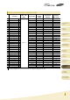
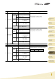
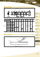
Test Condition
Q
Tan
Electrical
Characterization
Capacitance
Solderability
Item
Within specified tolerance
No abnormal exterior appearance
No dielectric breakdown or mechanical
breakdown
No abnormal exterior appearance
More than 100,000
or 1,000
(Whichever is smaller)
More than 10,000 or 500
(Whichever is smaller)
More than 10,000
or 100
(Whichever is smaller)
More than 1,000
or 10
(Whichever is smaller)
The Capacitance /D.F. should be measured at 25,
I.R. should be measured with a DC voltage not exceeding
Rated Voltage @25, @125 for 60~120 sec.
Dielectric Strength : 250% of the rated voltage for 1~5 seconds
The charge/discharge current is less than 50mA.
a) Preheat at 155 for 4 hours, Immerse in solder for 5s at 2355
b) Steam aging for 8 hours, Immerse in solder for 5s at 2355
c) Steam aging for 8 hours, Immerse in solder for 120s at 2605
solder : a solution ethanol and rosin
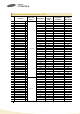
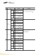
Beam speed
Chip Length
2.5 , 0.50.05 /sec
Chip Length 3.2 , 2.50.25 /sec
Bending to the limit for 5 seconds
Limit : ClassⅠ- 3mm
Class Ⅱ - 2mm
18N, for 601 sec.
* 0603(1608)
10N,
0402(1005) 2N
Performance
15
16
18
No
CLASSⅡ
CLASSⅡ
95% of the terminations is to be soldered
evenly and continuously
Capacitance 30 : Q 1,000
30 : Q 400 +20C
( C: Capacitance)
Rated Voltage 25V : 0.025 max
16V : 0.035 max
10V : 0.05max
CLASSⅠ
CLASSⅠ
CLASSⅡ
CLASSⅠ
CLASSⅡ
CLASSⅠ
CLASSⅡ
CLASSⅠ
CLASSⅡ
CLASSⅠ
CLASSⅠ
CLASSⅠ
Board Flex
Terminal
Strength(SMD)
IR@25
IR@125
17
Dielectric Strength
Appearance
Appearance
Beam Load
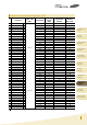
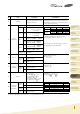
Capacitance
Temperature
Characteristics
19
20
Destruction value should be exceed
Chip Length 2.5
a) Chip Thickness > 0.5 : 20N
b) Chip Thickness 0.5 : 8N
Chip Length 3.2
a) Chip Thickness 1.25 : 54.5N
b) Chip Thickness < 1.25 : 15N
Capacitance
Change
Capacitance
Change
Capacitance
Change
Capacitance
Drift
Temperature
Coefficient
Within 5.0% or 0.5pF,
(Whichever is larger)
Within 2.5% or 0.25pF,
(Whichever is larger)
Within 0.2% or 0.05pF,
(Whichever is larger)
Within 10%
Within 10%
Within 15%
030 ppm/
030 ppm/
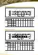
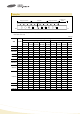
Class
ClassⅠ
ClassⅡ
Capacitance
1000pF
1000pF
10
10
Frequency
1
10%
1 10%
1 10%
120 20%
Vrms
0.5~5Vrms
1.0
0.2Vrms
1.0 0.2Vrms
0.5 0.1Vrms
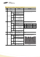
Step
Temperature()
Time(min)
25 2
Min. Operating Temp. 2
25 2
Max. Operating Temp. 2
25 2
1
153
1
153
1
1
2
3
4
5
* For the more detail Specification, Please refer to the Samsung MLCC catalogue.
Part Numbering
System
High Capacitance
Capacitors
Super Small Size
Capacitors
Medium-High
Voltage Capacitors
Array Type
Capacitors
Low ESL
Capacitors
Application Manual
for Surface Mounting
Packaging
Specification
Premium Capacitors
for Automotive
Applications
Reliability Test
Condition
General
Capacitors