
Datasheet


82
83
Since a multilayer ceramic chip capacitor comes into direct contact with melted solder during soldering, it is exposed to potentially mechanical
stress caused by the sudden temperature change. The capacitor may also be subject to silver migration, and to contamination by the flux.
Because of these factors, soldering technique is critical.
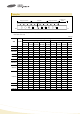
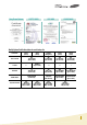
6-1. Soldering Methods
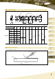
4-1. Mounting Head Pressure
Excessive pressure will cause chip capacitors to crack. The pressure between nozzle and chip capacitor will be 300g maximum during mounting.
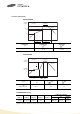
4-2. Bending Stress
Bending of printed circuit board by mounting head when double-sided circuit boards are used, chip capacitors first are mounted and soldered onto
one side of the board. When the capacitors are mounted onto the other side, it is important to support the board as shown in the illustration.
If the circuit board is not supported, it may bend, causing the already-installed capacitors to crack.
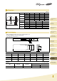
Although highly-activated flux gives better solderability, substances which increase activity may also degrade the insulation of the chip
capactiors, To avoid such degradation, it is recommended that a mildly activated rosin flux ( less than 0.2% chlorine ) be used.
Method
Reflow
slodering
Overall
heating
Infrared rays
Hot plate
VPS (Vapor phase)
Air heater
Laser
Light beam
Local
heating
Single wave
Double wave
Flow
Soldering
Classification
nozzle
force
support pin
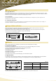
6-2. Soldering Profile
To avoid the crack problem by sudden temperature change, follow the temperature profile in the adjacent graph.
4. Mounting
5. Flux
6. Soldering
Part Numbering
System
High Capacitance
Capacitors
Super Small Size
Capacitors
Medium-High
Voltage Capacitors
Array Type
Capacitors
Low ESL
Capacitors
Application Manual
for Surface Mounting
Packaging
Specification
Premium Capacitors
for Automotive
Applications
Reliability Test
Condition
General
Capacitors