CHEMTRONICS Wall Cableless _ TX User Manual Product Name Model Name Version Date Wall Cableless _ TX CTTAK3I01 0.
Revision History Version Date Description 0.
Contents 1. Overview................................................................................................................................................................................ 4 2. System Specification .......................................................................................................................................................... 5 2.1 Physical feature .............................................................................................................
1. Overview This product is a module developed to process video signals in the 60GHz band using the built-in KSS104M chip. Since multiple chips are used on one board, the spacing between chips and chips should be at least 15mm. In addition, the TX Chip of this product receives video signals from the outside and transmits them to the Rx Chip of the KSS104M RX Board. In particular, by using an interface that transmits an electrical signal called V-By-one, video transmission can proceed very quickly.
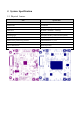
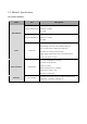
2. System Specification 2.1 Physical feature Item Specification Product Name Wall Cableless _ TX Model Name CTTAK3I01 Communication Method EHF(Extremely High Frequency, 60GHz) Link Dimension 80.00mm x 80.00mm x 1.4mm(T) Weight 24g Mounting Type Wafer(6Pin Header), OCM Connector(44Pin) Other subsidiary materials ECCOSORB(EMI Absorber) Mutual of the person being certified CHEMTRONICS Co., Ltd Manufacturer/country of manufacture CHEMTRONICS Co.
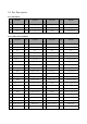
2.2 Pin Description 2.2.1 Wafer(6Pin) Pin Pin Pin Name Type Function No. Pin Name Type Function No. 1 RSV I/O Receive Signal Check 2 INFO_3.3V_1 P 3.3V Power Check 3 INFO_3.3V_2 P 3.3V Power Check 4 PS_ON I/O PS-ON Signal I/O 5 RSV2 I/O Receive Signal Check 6 GND P Digital Ground Pin Name Type Function 2.2.2 OCM Connector(44Pin) Pin Pin Pin Name Type Function No. No.
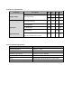
2.3 Module Specification 2.3.1 Product Summary Item P/N Description - Signal Processing : NO KQG104-B3-TXS-E - Data Rate : 5.4Gbps - EQ : 6dB KSS104M IC - Signal Processing : NO KQG104-B3-RXS-E - Data Rate : 5.4Gbps - PE : 6dB - Adjustable Output Low to 0.9V - Input Voltage as Low as 1.0V and VPP Voltage 5V LDO - Over Current and Over Temperature Protection G943F11U - Low Reverse Leakage (Output to Input) - Apply GND to PIN of SET 1 and 3.3V to PIN of SET 2. So that 1.
2.3.2 Electrical Specification Parameter Description Supply Voltage Min. Typ. Max. Units 3.1 3.3 3.5 V 1.6 1.8 2 V LDO Output Voltage 1.0 1.2 1.4 Eye Height(EH) 135 mA Eye Width(EW) 129.64 Ps Main Input Voltage Output Voltage Signal Spec Total Jitter(TJ) 207.06 BER should be no FAIL for 60 seconds Signal Sensitivity (TX B/D to RX B/D distance:10mm) 60 2.3.
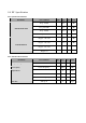
2.4 RF Specification 2.4.1 System Characteristics Parameter Test Condition Min. Typ. Max. Units Freq : 57GHz 4.1 dBi Freq : 60.5GHz 5.2 dBi Freq : 61GHz 5.3 dBi Freq : 64GHz 4.9 dBi Degree : -30 or 30 2.3 dBi Degree : -20 or 20 3.3 dBi Degree : -10 or 10 4.3 dBi Degree : 0 5.3 dBi Antenna Peak Gain Antenna Pattern 2.4.2 Antenna Characteristics Parameter Test Condition Frequency Range Typ. Max. Units 57 64 GHz 60.
3. Module Assembly Be careful not to damage the module. Pressing hard on the KSS104M IC can affect the overall performance.
FCC MODULAR APPROVAL INFORMATION EXAMPLES for Manual This device complies with Part 15 of the FCC Rules. Operation is subject to the following two conditions: (1) This device may not cause harmful interference. (2) This device must accept any interference received, including interference that may cause undesired operation. CAUTION: Changes or modifications not expressly approved by the party responsible for compliance could void the user's authority to operate the equipment.
OEM INTEGRATION INSTRUCTIONS: This device is intended only for OEM integrators under the following conditions: The module must be installed in the host equipment such that 20 cm is maintained between the antenna and users, and the transmitter module may not be co-located with any other transmitter or antenna. The module shall be only used with the internal on-board antenna that has been originally tested and certified with this module. External antennas are not supported.
Information that must be placed in the end user manual: The OEM integrator has to be aware not to provide information to the end user regarding how to install or remove this RF module in the user's manual of the end product which integrates this module. The end user manual shall include all required regulatory information/warning as show in this manual.
FCC MODULAR APPROVAL INFORMATION EXAMPLES for Manual This device complies with Part 15 of the FCC Rules. Operation is subject to the following two conditions: (1) This device may not cause harmful interference. (2) This device must accept any interference received, including interference that may cause undesired operation. CAUTION: Changes or modifications not expressly approved by the party responsible for compliance could void the user's authority to operate the equipment.
IC Information This device complies with Industry Canada license-exempt RSS standard(s). Operation is subject to the following two conditions: (1) this device may not cause interference, and (2) this device must accept any interference, including interference that may cause undesired operation of the device. Cet appareil est conforme avec Industrie Canada exempts de licence standard RSS (s).
Requirement per KDB996369 D03 2.2 List of applicable FCC rules List the FCC rules that are applicable to the modular transmitter. These are the rules that specifically establish the bands of operation, the power, spurious emissions, and operating fundamental frequencies. DO NOT list compliance to unintentional-radiator rules (Part 15 Subpart B) since that is not a condition of a module grant that is extended to a host manufacturer. See also Section 2.
Explanation: Clear and specific instructions describing the conditions, limitations and procedures for third-parties to use and/or integrate the module into a host device (see Comprehensive integration instructions below). Resolve: Installation Notes: 1) Power Supply: The host product should supply the regulated power of 1.8 V, 3.3 V DC to module. 2) Make sure the module pins correctly installed.
2.5 Trace antenna designs For a modular transmitter with trace antenna designs, see the guidance in Question 11 of KDB Publication 996369 D02 FAQ – Modules for Micro-Strip Antennas and traces. The integration information shall include for the TCB review the integration instructions for the following aspects: layout of trace design, parts list (BOM), antenna, connectors, and isolation requirements. a) Information that includes permitted variances (e.g.
2.7 Antennas A list of antennas included in the application for certification must be provided in the instructions. For modular transmitters approved as limited modules, all applicable professional installer instructions must be included as part of the information to the host product manufacturer. The antenna list shall also identify the antenna types (monopole, PIFA, dipole, etc. (note that for example an “omni-directional antenna” is not considered to be a specific “antenna type”)).
2.10 Additional testing, Part 15 Subpart B disclaimer The grantee should include a statement that the modular transmitter is only FCC authorized for the specific rule parts (i.e., FCC transmitter rules) listed on the grant, and that the host product manufacturer is responsible for compliance to any other FCC rules that apply to the host not covered by the modular transmitter grant of certification.