GEMS‐H Instructions for Use
Publishing details GEMS‐H Powered Lower Extremity Exoskeleton, Instructions for use Document No.: SAIT‐IFU‐GEMS‐H Revision No.: 1.1 Revision date: 2019. 11. 05 Application version: 1.4 Manufacturer Samsung Electronics Co., Ltd. 129, Samsung‐Ro, Yeongtong‐Gu, Suwon‐Si, Gyeonggido, Republic of Korea, 16677 +82‐31‐8061‐1114 www.samsung.com Copyright This document is protected by copyright. All rights reserved.
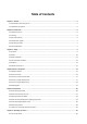
Table of Contents Chapter 1. General ................................................................................................................................................... 5 1.1. About these instructions for use ............................................................................................................................... 5 1.2. Explanation of symbols .................................................................................................................................
6.2. Opening and closing the GEMS‐H application ........................................................................................................ 31 6.3. Login screen ............................................................................................................................................................ 33 6.4. Overall GEMS‐H user interface ............................................................................................................................... 35 6.5.
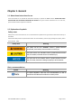
Chapter 1. General 1.1. About these instructions for use These instructions for use provide the information necessary to operate the GEMS‐H device. PLEASE READ THESE INSTRUCTIONS FOR USE BEFORE OPERATING THE SYSTEM. If any part of these instructions for use is not clear, please contact Customer Support for assistance. 1.2. Explanation of symbols Safety notes Safety notes in these instructions for use are introduced with a symbol and a signal word to describe the severity of the hazard.
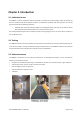
Chapter 2. Introduction 2.1. Indications for use The GEMS‐H is a robotic exoskeleton that fits orthotically on the wearer’s waist and thigh, outside of clothing. The device is intended to help assist ambulatory function in rehabilitation institutes under the supervision of a trained physical therapist for the following population: Individuals with stroke who have gait deficits and exhibit gait speeds of at least 0.4 m/s and are able to walk at least 10 meters with assistance from a maximum of one person.
2.4. Intended user profile Occupation • Physical therapists Education • Earned a degree in physical therapy and obtained a current physical therapist license. • Familiar with the application of the tablet PC. • Be able to set up the Bluetooth communication between the device and the tablet PC. • Complete a training program provided by Samsung on how to use the device. Experience / Abilities 2.5.
For further information with regard to the clinical studies, refer to “Chapter 11. Clinical studies”. SAIT‐IFU‐GEMS‐H Rev.1.
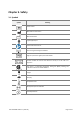
Chapter 3. Safety 3.1. Symbols Symbol Meaning Serial number Manufacturer information Manufacture date Type B applied part Follow instructions for use Non‐ionizing electromagnetic radiation Degree of protection against particulate matter Caution: Federal law restricts this device for sale by or on the order of a physician This mark is a Nationally Recognized Testing Lab (NRTL) marking and indicates conformance with UL 60601‐1.
3.2. Safety Risk of electrical shock hazard and performance degradation if this equipment is modified! Unauthorized modification of this equipment can affect the safety and effectiveness of the equipment. ‐ Do not modify this equipment without authorization of the manufacturer. Risk of serious injury due to misuse! Use of the device without training can result in serious injury to the patient. ‐ Users must successfully complete a training program provided by Samsung prior to use of the GEMS‐H.
Risk of serious injury to the patient due to loss of control! Should the therapist lose control of the device, or if a device is used without the supervision of the trained physical therapists, this may result in the patient having difficulty balancing and potentially falling while using the device. ‐ At least one therapist should monitor patients at all times while the devices are turned on and/or while the patients are walking.
Risk of injury to the patient and device damage due to sitting and leaning backward on a surface while wearing the device! If the patient wearing the device sits and leans back onto a surface (e.g., chair), it may cause discomfort, skin pressure, and/or device damage. ‐ Do not lean backward onto a surface while wearing the device and sitting.
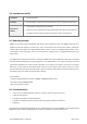
3.4. Environmental conditions Operation Storage & Transport Temperature 32 ℉ to 86 ℉ (0 ℃ to 30 ℃) ‐ 77 ℉ to 158 ℉ (‐ 25 ℃ to 70 ℃) Humidity 30 to 85 % (non‐condensing) 10 to 94 % (non‐condensing) Pressure 700 hPa to 1060 hPa 500 hPa to 1060 hPa 3.5. Disposal This device contains electrical and electronic equipment waste, which must be disposed of separately from unsorted municipal waste.
Chapter 4. Device description 4.1. Package contents The GEMS‐H sales package contains the following items: Waist part (Sizes: S, M, L) Thigh support frame (Sizes: S, M) Thigh support strap with buckles (Sizes: S, M, L) Tablet PC Tablet PC case Device charger Tablet PC charger Hip width ruler Extension belt Torque wrench Storage case Instructions for use Depending on the wearer’s size, these components are used in combination.
Device charger Tablet PC charger Hip width ruler Extension belt Torque wrench Storage case Tablet PC case (optional) Instructions for use SAIT‐IFU‐GEMS‐H Rev.1.
4.2. Device overview No. Parts Description 1 Control pack 2 Battery 3 Power switch 4 Waist belt 5 Actuator module 6 Thigh support frame Rigid frame delivering the assistive force to the wearer’s thigh 7 Thigh support strap Fastening strap connecting the thigh support frame and to the wearer’s thigh SAIT‐IFU‐GEMS‐H Rev.1.
4.3. Accessory: waist extension belt The extension belt may be used to increase the length of the waist belt by 5.9 inches (150 mm). It is used when the waist belt of the device is too short to fasten completely and comfortably around the patient’s waist. 4.4. Accessory: thigh support frame Length, inches (mm) SAIT‐IFU‐GEMS‐H Rev.1.1 (2019‐11) Small size Medium size 9.1 (230) 10.
4.5. Accessory: thigh support strap Length, inches (mm) SAIT‐IFU‐GEMS‐H Rev.1.1 (2019‐11) Small size Medium size Large size 14.2 (360) 16.1 (410) 17.
4.6. Marking plate SAIT‐IFU‐GEMS‐H Rev.1.
Chapter 5. Preparation 5.1. Device fitting procedure ① Measure the wearer’s hip width using the provided hip width ruler. ② Select the appropriate waist part size according to the wearer’s hip width. ③ hip width: 12.4 ~ 14.4” (315 ~ 365 mm) Small hip width: 14.0 ~ 15.9” (355 ~ 405 mm) Medium hip width: 15.9 ~ 17.9” (405 ~ 455 mm) Large Use the torque wrench provided to adjust the waist part width according to the wearer’s hip width.
5.2. Determine the waist part size 5.2.1. Waist part size The device width can be adjusted within a range of about 2 inches (50 mm) by adjustment of the waist part. Small [inches (mm)] Medium [inches (mm)] Large [inches (mm)] Hip width 12.4 ~ 14.4 (315 ~ 365) 14.0 ~ 15.9 (355 ~ 405) 15.9 ~ 17.9 (405 ~ 455) Waist depth 5.7 ~ 6.7 (145 ~ 170) 7.9 ~ 9.8 (200 ~ 250) 9.4 ~ 12.2 (240 ~ 310) Waist circumference 30.7 ~ 34.3 (780 ~ 870) 32.3 ~ 36.2 (820 ~ 920) 36.2 ~ 43.
5.2.2. Hip width measurement When the measured hip width falls between the applicable size ranges of two different devices, it is recommended that the device of the bigger size be selected. A 10 mm margin of safety is automatically included on each side by the hip width ruler provided, as shown below, and is usually suitable if the measurement is taken loosely. If the device is still too tight, the user should adjust the device for patient comfort at their discretion. ① Identify the hip joint location.
5.2.3. Size markings The size of the waist part is indicated on the front clasp (S, M, and L). 5.3. Adjust the waist part width Property damage when the screws are over tightened! The product may be damaged if the screws are over tightened or continuously tightened after clicking sounds are emitted from the torque wrench provided. ‐ Do not tighten further after clicking sounds emit from the torque wrench provided.
③ Use the provided torque wrench to loosen both screws. Turn counter‐clockwise (CCW) to loosen. ④ Check the ruler scale on the upper beams (metric‐based, one tick mark indicates 10 mm), and adjust the width by holding the lower beams and applying a gentle force. ⑤ Once the waist part has been adjusted to the appropriate size, use the provided torque wrench to tighten (turn clockwise) the screws until the wrench clicks. 5.4.
Risk of potentially falling due to the loosened waist belt! If the device is used frequently, Velcro on the waist belt may lose its adhesion. If the patient wears the thigh support strap loosely during rehabilitation, this may result in the patient having difficulty balancing, and potentially falling. ‐ Check whether the waist belt is fastened before walking.
⑥ Use a Medium‐size thigh support frame initially, and use a Small‐size if the length of the wearer’s thigh is somewhat short (i.e., if the thigh support frame comes in contact with the knee cap). ⑦ The size is indicated on the release button of the thigh support frame (S, M). 5.5.
The therapist can use a different size selection for the waist part, thigh support frame, and thigh support strap for each patient. For example, the therapist can select the Medium waist part, the Small thigh support frames, and the Large thigh support straps, and so on. ① Use a Medium‐size thigh support strap initially. Switch to Small or Large‐size if needed. ② Fasten both thigh support straps by attaching the buckles on the strap to the thigh support frame.
5.6. Waist part position Risk of serious injury due to incorrect waist part positioning! Incorrect waist part positioning on the patient could cause discomfort, skin pressure/friction, bruising, pain, or unusual swelling. ‐ Before turning the device on, ask the patient to walk in place to check for any discomfort. If so, reposition the device or try donning the device again. The therapist may need to re‐adjust the waist part width or the tightness of the waist belt.
5.7. Check prior to use/operation of the device 5.7.1. Check for before use ① Check that the screws for adjusting the hip width of the waist part are not loose. ② Check that the thigh support frame fastening hook and strap Velcro are securely fastened. ③ Use the device after it is fully charged. Monitor the battery level and if the battery level is below 20 %, charge the device before use. 5.7.2.
Chapter 6. Operating the device 6.1. Turn on the device Turn on the power switch by pushing it up. The indicator light (Power LED) will turn green. Then check that the front left and right LEDs (Control LED) are ON, which indicates that the device is booting up. This may take up to 15 seconds. When device is ready for operation, only the orange light is on.
6.2. Opening and closing the GEMS‐H application 6.2.1. Opening the GEMS‐H application An android application controls and monitors the GEMS‐H using Bluetooth communication. Press the “GEMS‐H” icon on the home screen of the tablet PC to execute the application and it will show the login screen. SAIT‐IFU‐GEMS‐H Rev.1.
6.2.2. Closing the GEMS‐H application If you want to close the application, 1) Press the “Recent apps” button at the bottom left of the home screen, as shown below. 2) Press the “Close all” button. If the user does not close the application properly, the following message will appear when the application is run again. Please press the “RESTART” button to start the application anew, or press the “CONTINUE” button to continue using the current application. SAIT‐IFU‐GEMS‐H Rev.1.
6.3. Login screen The user and the administrator passwords should be managed by the authorized administrator. In particular, the administrator password should not be exposed to patients and non‐administrators. 6.3.1. Logging in ① A physical therapist may use the app as a general user by using a password given by an administrator. ② Administrators can change the user password with admin password in order to manage authorized users. 6.3.2.
① Click “Change password”. ② Enter the admin password. ③ Select “user” or “admin” and save the new password. SAIT‐IFU‐GEMS‐H Rev.1.
6.4. Overall GEMS‐H user interface 1) Patient Info Tab User interface to manage patient information (See section 6.5 The ‘Patient Info’ tab for details). 2) Device Connect Tab User interface for connecting the device using Bluetooth (See section 6.6 The ‘Device Connect’ tab for details). 3) Device Control Tab User interface to control the device (See section 6.7 The ‘Device Control’ tab for details). SAIT‐IFU‐GEMS‐H Rev.1.
6.5. The ‘Patient Info’ tab Be sure to ask the patient whether the information is correct or not. Select the patient ID from the list and load the information accordingly. Give a new patient ID for the first‐time patients and specify name, gender, age, height, weight, and note associated with a patient ID. Patient information is only for user reference and does not affect any functions of the device. Therefore, input of patient information can be skipped. SAIT‐IFU‐GEMS‐H Rev.1.
. Press the “SAVE” button to save the patient ID and associated patient information. If you use a patient ID that already exists, all previous information will be updated with the new information. Press the “DEL” button to delete patient ID and associated information. SAIT‐IFU‐GEMS‐H Rev.1.
Uncheck “Unit (US)” in order to use SI Units instead of US Units. SAIT‐IFU‐GEMS‐H Rev.1.
6.6. The ‘Device Connect’ tab ① Check the device name on the top of the clasp. ② Select the name of the device to enable so that it is highlighted in yellow. Press the “SCAN” button again if the desired device is not found. ③ Connect the selected device by pressing the “CONNECT” button. message will appear and the text on the button will changed to “DISCONNECT”. SAIT‐IFU‐GEMS‐H Rev.1.
6.7. The ‘Device Control’ tab The screen configuration of the ‘Device Control’ tab is shown below. SAIT‐IFU‐GEMS‐H Rev.1.
6.7.1. Monitoring area 1) Monitoring option Device and patient information may be monitored as a graph or as text. Press the “Monitoring Option” button to open the “Monitoring Option Screen”. In the monitoring option screen, the user may select data to be displayed on the main screen graphically or textually. These selections may be made by checking “Graph” or “Text” in the relevant row of the monitoring option screen. The “MAX” column shows the graph range for each monitoring data.
① The “Max” label on graph view refers to the max value in the monitoring option screen as shown below: ② Legend of selected data as shown below: ③ The following table explains the meaning of the possible monitoring data variables: JointAngL left hip joint angle JointAngR right hip joint angle JointVelL left hip joint angular velocity JointVelR right hip joint angular velocity JointTrqL left hip assist torque, measured JointTrqR right hip assist torque, measured ImuEulerX Euler angle of X axi
ImuGyroX angular velocity of X axis from the IMU sensor ImuGyroY angular velocity of Y axis from the IMU sensor ImuGyroZ angular velocity of Z axis from the IMU sensor ImuAccX acceleration of X axis from the IMU sensor ImuAccY acceleration of Y axis from the IMU sensor ImuAccZ acceleration of Z axis from the IMU sensor LeftButton currently not available RightButton currently not available ControlTrqL left hip torque goal from the algorithm ControlTrqR right hip torque goal from the algori
4) Text Screen [Patient Info] Patient ID and name. [Device Info] Device ID, time duration since power on and battery level. [Mod e ] SAIT‐IFU‐GEMS‐H Rev.1.
6.7.2. Assist control area 6.7.2.1. Set the stand pose Make sure that hip angle is as close to neutral as possible with the patient standing naturally. If the patient is walking with their back bent, their neutral posture will also be standing with back bent. Incorrect setting of the stand pose may cause uncomfortable assistance or degrade clinical effectiveness. Make sure that both the left and right joint angle options are selected within the monitoring option dialog.
6.7.2.2. Set assist mode ① By pressing the “Set Assist Mode” button, the therapist can change the assist mode and parameters. ② At present, only the Walk Assist mode is provided. ③ Pre‐saved assist parameters can be selected. The default parameters are available as “Normal,” and an additional saved parameter set called “Strong” is available by default. ④ Assist parameters can be saved with a user‐defined name using the “Save” button.
6.7.2.3. Start/Stop assistance 1) Start assistance ① Press the “START” button to run the assistance algorithm. ② If the algorithm runs properly, the tablet PC interface and the LEDs on the device will change as shown below. 2) Stop assistance ① Press the “STOP” button to stop the assistance algorithm. ② If the algorithm stops properly, the tablet PC interface and LEDs on the device will change as shown below. SAIT‐IFU‐GEMS‐H Rev.1.
6.7.3. The parameter control area 6.7.3.1. Parameter control descriptions The parameter control area contains a number of parameters that can be controlled by the user while therapy is in progress. The following illustrations and table describe the use of the parameter control area. Assist pattern changes by controlling parameters SAIT‐IFU‐GEMS‐H Rev.1.
Parameter GUI element Function Adjust assist strength to be weak or strong. Gradually increase the gain after confirming that the torque is not too strong for the wearer. Each press will change the parameter by 0.2. This parameter ranges from 0 to 15. The default setting is 7 and usually assists around 5 Nm.
Parameter GUI element Function GainL +/‐ Adjust assist strength of left leg only. GainR +/‐ Adjust assist strength of right leg only. Disable Joint Limit Turn off joint limit monitor (extension 40 degree ~ flexion 100 degree) which is used for safety functions. Free Motion The device gives no assistive force, and moves itself just enough to follow the patient as the patient moves. Lock Buttons Disable all buttons to prevent accidental button presses.
1) Control parameters: Gain, Delay parameters As shown in the figure below, the user can monitor parameter adjustments. If a parameter is adjusted beyond the defined parameter range, the parameter will not change. 2) Monitor parameter: Maximum Torque Parameters (MaxTrqL, MaxTrqR) Users can monitor the maximum assistive torques that the device delivers to the patient as the user changes the assist gain.
6.7.3.3. Example of parameter control SAIT‐IFU‐GEMS‐H Rev.1.
6.8. Safety features 6.8.1. Mitigation of risks related to a fully discharged Lithium Ion battery The Li‐ion battery used in this device has a risk of explosion and of material leakage when completely discharged. To prevent this, the power control module (PCM) circuit is designed to fundamentally cut off the power before the battery discharges fully. In addition, the battery level is continuously measured and displayed on the application.
Error message examples SAIT‐IFU‐GEMS‐H Rev.1.
6.8.2. Mitigation of risks due to excessive power output In order to avoid an excessive torque being applied to the patient, the device is designed to not to transmit a torque of more than 12 Nm ±15 % to the patient. When the assistive force reaches the predetermined maximum force, then the device will cease applying the assistive force.
6.8.3. Mitigation of risks due to excessive joint angle movement The GEMS‐H joints have mechanical stoppers to restrict over‐extension of joints, as well as software limits on joint movement. The mechanical stoppers are designed to ensure that the hip joints stay within the specified range even in the case of a malfunctioning device. The mechanical stoppers are set to a maximum of 110 degrees for flexion and a maximum of 45 degrees for extension.
6.8.4. Mitigation of risks due to disconnection from the tablet PC When using the GEMS‐H, status monitoring and operation are done through a tablet PC via Bluetooth wireless communication. If the Bluetooth communication is interrupted, the monitoring and control of the GEMS‐H are designed to cease, but the device will continue operation.
6.8.5. Mitigation of risks due to abnormal actuator module status If the actuator module does not work properly during use, the controller may generate abnormal power. The actuator module is monitored continuously during treatment, and when an abnormality is detected, the assistive force is turned off.
Chapter 7. Shutdown 7.1. Stop the assistance When the “STOP” button is touched on the tablet PC, the device will cease applying assistive force and buttons in the Assist Control Area will deactivate. 7.2. Turn off the device Turn off the power switch by pushing it down. The green power LED indicator will turn off. SAIT‐IFU‐GEMS‐H Rev.1.
7.3. How to take off the device ① Unfasten the thigh support straps. ② Push the release button on the thigh support frame to unhook the thigh support frame. ③ Detach both thigh support frames. ④ Unfasten the waist belt Velcro. ⑤ Open the waist belt and remove the device from the wearer’s waist. Be careful not to let the device fall. ⑥ Charge the device before its next use and place it in the storage case provided if use is not anticipated. SAIT‐IFU‐GEMS‐H Rev.1.
Chapter 8. Maintenance 8.1. Storage To prevent damage during storage, it is recommended that the thigh support frames and the waist part are disconnected prior to storage.
8.2. Regular maintenance (Weekly Checklist) Check that the bolts on the actuator cover are not loose. Check that the bolts on the battery cover are not loose. Check that the bolts on the thigh support frame are not loose. 8.3. Cleaning Risk of electrical shock hazard due to moisture! Electrical shock may be delivered to the patient and the user due to excessive moisture when the device is turned on while cleaning. ‐ Do not clean while in use. ‐ Be sure to turn off the power before cleaning.
④ Dampen (but do not soak) a lint‐free cloth with purified water. ⑤ Wipe the surface of the device for at least five (5) minutes. ⑥ Let the device dry completely in air. ⑦ Store the device in its storage case provided until the next use. 8.4. How to charge the GEMS‐H Property damage may occur when the charger cable receives any force! If the charger cable receives any force when the terminal pin is plugged in, the connector of the charger cable can be damaged beyond repair.
SAIT‐IFU‐GEMS‐H Rev.1.
Chapter 9. Troubleshooting Property damage may occur due to improper repair. If personnel other than authorized by the manufacturer carries out the repair, it may irreversibly damage the device. ‐ Repair should only be performed by the manufacturer. 9.1. Troubleshooting Issue The hip joint of the device becomes stuck during operation. Recommended action(s) • If the actuator becomes stuck during operation, do not apply excessive force to the device. • First, turn off and then take off the device.
Issue Recommended action(s) • • The following malfunctions: ‐ The assistive force suddenly ceases without any reasons. ‐ The assistive forces are being delivered to the patient, but hip angles and torques are not displayed on the connected tablet PC. ‐ • • • Restart the GEMS‐H Device. (Use the power switch located at the bottom of the control pack). If the above procedure does not solve the problem, the actuator may not be in a normal state. Please contact the manufacturer of the device.
SAIT‐IFU‐GEMS‐H Rev.1.
Messages [Error] EXCEEDED TORQUE LIMIT Causes Recommended action(s) When this message is displayed and the device is stopped, the physical therapist may try to start the device again by pressing the “START” button on the tablet PC. If the problem persists, reboot the device and the tablet PC. If there is still a problem with the device, turn off the device immediately and contact the manufacturer.
Messages [Warn] DISCONNECTED Causes Recommended action(s) The physical therapist should stop the current treatment and reconnect the tablet PC. When the tablet PC is reconnected to the GEMS‐H, the application will display the message “CONNECTED”, and the tablet PC resumes operation. [Status] NORMAL OPERATION n/a [Status] CONNECTED n/a SAIT‐IFU‐GEMS‐H Rev.1.
Chapter 10. Technical specifications 10.1. Specifications Device Sizes Battery S, M, and L size Rechargeable lithium ion, 21.6 V, 2950 mAh, 2 hrs charge time Minimum 2 Hr. of continuous walking* (with gain = 7, delay = 0.25 s) Working time Minimum 1 Hr. of continuous walking* (with gain = 8, delay = 0.25 s) * at a walking speed of about 1.9 ~ 2.5 MPH (0.8 ~ 1.1 m/s) Device Weight Range of Motion Actuator Spec. Failsafe Feature 4.7 lbs (2.
Model: JBL7451251700002FJ Device Charger* Manufacturer: BRIDGEPOWER CORP. Input: 100 ‐ 240 Vac, 50 ‐ 60 Hz, 1.0 A Output: 25.2 Vdc, 1.7 A Model: Galaxy Tab S5e Manufacturer: Samsung Electronics Co., Ltd. Tablet PC* Battery: 7040 mAh CPU: Octa‐Core, 2 GHz, 1.7 GHz Display: Super AMOLED, 2560 x 1600, 10.5 inch(267.2 mm) Network: 2G GSM, 3G UMTS, 4G FDD LTE, 4G TDD LTE Model: EP‐TA20JBE Tablet PC Charger* Manufacturer: Samsung Electronics Co., Ltd. Input: 100 ‐ 240 Vac, 50 ‐ 60 Hz, 0.5 A Output: 9.
10.2. EMC (Electromagnetic Compatibility) Risk of serious injury due to radiation! Use of this equipment adjacent to or stacked with other equipment should be avoided because it could result in improper operation. If such use is necessary, this equipment and the other equipment should be observed to verify that they are operating normally.
EMC Table – Guidance and manufacturer’s declaration Electromagnetic emissions The GEMS‐H is intended for use in electromagnetic environments, as specified below. The customer or the user of the GEMS‐H should ensure that it is used in such an environment. Emission test Compliance Electromagnetic environment – guidance RF emissions CISPR11 Group 1 The GEMS‐H uses RF energy only for its internal function.
Guidance and manufacturer's declaration ‐ electromagnetic immunity The GEMS‐H is intended for use in the electromagnetic environment specified below. The customer or the user of the GEMS‐H should assure that it is used in such an environment. IEC 60601 test level Immunity test Compliance level Electromagnetic environment‐ guidance Portable and mobile RF communications equipment should be used no closer to any part of the GEMS‐H, including cable.
Recommended separation distance between portable and mobile RF communications equipment and the GEMS‐H The GEMS‐H is intended for use in an electromagnetic environment in which radiated RF disturbances are controlled.
LTE Band 1,2,4,25 UMTS 2400 – 2570 MHz Bluetooth Pulse modulation WLAN 217 Hz 28 V/m 28 V/m 9 V/m 9 V/m 802.11b/g/n RFID 2450 LTE Band 7 5100 – 5800 MHz WLAN 802.11a/n Pulse modulation 217 Hz NOTE : These guidelines may not apply in all situations. Electromagnetic propagation is affected by absorption and reflection from structures, objects and people. a For some services, only the uplink frequencies are included. 10.3. FCC 10.3.1.
Chapter 11. Clinical studies 11.1. Introduction In 2019, Samsung conducted a clinical study of the GEMS‐H device primarily to evaluate the safety and efficacy of using the GEMS‐H device in the outpatient setting for post‐stroke rehabilitation. In addition, the effects on functional ambulation are also being investigated in this project. The primary objectives are: 1) To determine safety and efficacy of Samsung GEMS‐H during physical therapy care in an outpatient setting for post stroke individuals.
11.3. Summary of studies Clinical trial summary (Pivotal study) – from 2019.11 Title Protocol Number Methodology Safety and Efficacy of Samsung GEMS‐H Device to improve Functional Walking Ability in Outpatient Stroke Rehabilitation.
Statistical methods Multiple ANOVAs Performance results: Primary performance endpoints Secondary performance endpoints Summary conclusions Safety results: Primary safety endpoints Secondary safety endpoints Conclusions: NCT number SAIT‐IFU‐GEMS‐H Rev.1.