SCOPE2.0 Plus User Manual (GIS-PAMSC3) V0.
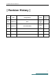
SCOPE2.0 Plus User Manual [ Revision History ] Version Date Change History V0.1 2016.11.13 Draft V0.2 2017.02.02 Add SCOPE2.0Plus author Sangho Lee Sangho Lee Confirmed by inho.won inho.
SCOPE2.0 Plus User Manual 1. Introduction SCOPE2.0 Plus is a device for transferring vibration signal and equipment information to an agent PC through wired/wireless communication. Users are advised to read carefully all manuals provided with the package, to ensure safe and efficient use of SCOPE2.0 Plus unit. This manual explains necessary skills and information for setting up and using SCOPE2.
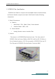
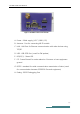
SCOPE2.0 Plus User Manual 2. SCOPE2.0 Plus Specification SCOPE2.0 Plus Platform comprise two boards(Main Board, Interface Board) and Sensor Module comprise one board. Each Board Contains following components 1) Board Components A. Platform i. Main Board : CPU / RAM / Flash / Power Module ii. Interface Board : WIFI / LAN B. Sensor Module i. Analog Vibration sensor interface Filter 2) Exterior This picture is of SCOPE2.0Plus Board and case. The front panel of SCOPE2.
SCOPE2.0 Plus User Manual Figure 2 SCOPE2.0 Plus Front Exterior A. Power : 24Vdc supply ( VCC / GND / FG) B. Antenna : Port for connecting WI-FI module C. LAN : LAN Port for Ethernet communication with other devices using TCP/IP D. USB : USB-OTG Port ( used for FW update) E. LED(1,2,3) : Status LED F. FG : Frame Ground for noise reduction. Connects to host equipment ground G. RS232 : standard for serial communication transmission of data ( used for communication between SCOPE2.0 Plus and equipment) H.
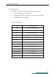
SCOPE2.0 Plus User Manual 3) H/W Specification A. SCOPE2.0 Plus internal H/W has following characteristics i. Freescale i.MX6 Qual Core(1 ㎓ × 4) ii. Dual Band WIFI, 802.11 a/b/g, LAN communication support iii. FPGA(SPARTAN LX4 )support B. Platform HW Details ITEM SPECIFICATION CPU Freescale-i.MX6Q CPU(Quad) ETHERNET 100M LAN SERIAL USB to SERIAL Debug port USB USB2.0 Client Debug port WIFI 802.11a/b/g ADC BOARD I/F 8bit Bus, 5V, 3.
SCOPE2.0 Plus User Manual C. Analog Vibration sensor module Details ITEM SPECIFICATION FPGA SPARTAN-6 ADC AD7684 x 4 FILTER IEPE(3MHz) INPUT ±5V SUPPLY POWER (1) 3.
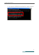
SCOPE2.0 Plus User Manual 3. How to install and Use 1) SCOPE2.0 Plus installations 2) SCOPE2.0 Plus Connection Check A. Change IP Address for Data PC to 192.168.0.5 B. Power On and confirm LED2 blinking green.
SCOPE2.0 Plus User Manual C. Do a ping test to SCOPE2.
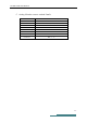
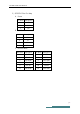
SCOPE2.0 Plus User Manual 3) SCOPE2.0 Plus Pin Map A. Power Pin Num Description 1 VCC 2 GND 3 FG B. LAN Port Pin Num Description 1 Tx+ 2 Tx- 3 Rx+ 4 Rx- C.
SCOPE2.0 Plus User Manual 4.
SCOPE2.0 Plus User Manual Federal Communication Statement Commission Interference This equipment has been tested and found to comply with the limits for a Class B digital device, pursuant to Part 15 of the FCC Rules. These limits are designed to provide reasonable protection against harmful interference in a residential installation.
SCOPE2.0 Plus User Manual This device complies with Part 15 of the FCC Rules. Operation is subject to the following two conditions: (1) this device may not cause harmful interference, and (2) this device must accept any interference received, including interference that may cause undesired operation Caution : Any changes or modifications in construction of this device which are not expressly approved by the party responsible for compliance could void the user's authority to operate the equipment.
SCOPE2.0 Plus User Manual [ Cable specification] . Power Cable - A ferrite Core is added to the Power input terminal(Number of turns / 1 turn) ( Using Power Source including a ferrite Core) .
SCOPE2.0 Plus User Manual . RS-232 Cable(4Port) - Apply Shielded Cable. ( Shield is connected to Frame Ground of SCOPE2.