
User's Manual


SCOPE2.0 Plus User Manual
4
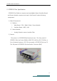
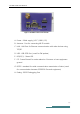
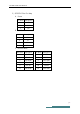
A. Power : 24Vdc supply ( VCC / GND / FG)
B. Antenna : Port for connecting WI-FI module
C. LAN : LAN Port for Ethernet communication with other devices using
TCP/IP
D. USB : USB-OTG Port ( used for FW update)
E. LED(1,2,3) : Status LED
F. FG : Frame Ground for noise reduction. Connects to host equipment
ground
G. RS232 : standard for serial communication transmission of data ( used
for communication between SCOPE2.0 Plus and equipment)
H. Debug : RS232 Debugging Port
Figure 2 SCOPE2.0 Plus Front Exterior