
User's Manual


Chapter 3 Connecting Cables
RFD01P Series Installation Manual v1.0 lx
Copyright © 2017, All Rights Reserved.
Cabling Diagram
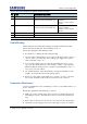
The cabling diagram of the RRU is as follows:
Figure 49. Cable Diagram
Table 25. RRU Connection Cable
From
To
Cable
MGB
RRU
1 Ground Cable
: AWG8 × 1C
RRU
Rectifier
2 Power Cable
: AWG 8 or AWG 10 × 2C
CDU or RRU
3 CPRI Cable
: Single Mode (Outdoor Type)
RRU
External Device
4 UDA Cable Assembly
RF Antenna
5 RET Cable Assembly
6 RF Cable
: 1/2 in. Feeder Line
The inlet hole finishing method of external equipment must be progressed after
consultation with operation company in case of the cable connected to external
equipment. (Optical distribution box, etc)
- The Cable: Power Cable, CPRI Cable, UDA Cable
RF Antenna
MGB
CDU or RRU
External Device
Rectifier
6) RF Cable
1) Ground Cable
3) CPRI Cable
4) UDA Cable
5) RET Cable
2) Power Cable
RRU