
User's Manual


Chapter 3 Connecting Cables
RFD01P Series Installation Manual v1.0 lxxiii
Copyright © 2017, All Rights Reserved.
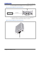
6 Insert the DLC plug to the system side’s optic module.
Figure 64. Connecting CPRI Cable_Cascade connection-oriented (5)
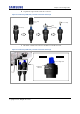
Insert the connector aligning the cable side connector’s white dot and system
side connector’s white dot. When inserting the connector, push the shell to
upper side.
Figure 65. Connecting CPRI Cable_Cascade connection-oriented (6)
Shell
Push
System side connector’s white dot
Cable side connector’s white dot
DLC Plug
System side’s optic
module