® ExoAtlet - II User’s Manual 이 사용설명서는 사전 통보 없이 제품의 개선을 위해 개정될 수 있습니다. 이 사용설명서의 이미지는 실제 제품과 다를 수 있습니다.
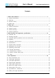
User’s Manual http://www.exoatletasia.com Contents 1. About User's Manual ················································································································ 3 1.1. General Information ······················································································································ 3 1.2. Warranty ··········································································································································· 3 1.3.
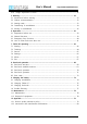
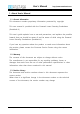
User’s Manual http://www.exoatletasia.com 4.10. Height adjustment of back ·································································································· 31 5. Wearing ······································································································································ 33 5.1. Precautions before wearing ······································································································ 33 5.2.
User’s Manual http://www.exoatletasia.com 1. About User's Manual 1.1. General Information This document contains proprietary information protected by copyright. This user manual is provided with the Powered Lower Extremity Exoskeleton (ExoAtlet®-II). This user's guide explains how to use and precautions, and explains the possible hazards that you should be aware of and be aware of while using the Powered Lower Extremity Exoskeleton (ExoAtlet®-II).
User’s Manual http://www.exoatletasia.com 1.4. Safety sign Symbols for safety signs are shown on the enclosure, on the packaging of the product and in this manual. Symbols provide users with important information such as caution, warning, and prohibition. Carefully read the symbols shown below and make good use of this information for product use and storage. This safety sign means caution.
User’s Manual http://www.exoatletasia.com 2. Safety sign 2.1. General instructions Notice Pilot recommended requirements 1 - Use for patients over 18 years old. - Please use it for the use of patient whose height is 160 cm ~ 190 cm. - Please use it for patients weighing less than 100 kg. Pilot Dress Recommendations - It is recommended to use sneakers with straps or Velcro. - Put on comfortable clothes that fit well.
User’s Manual http://www.exoatletasia.com 2.2. General caution Precautions before use Caution 1 If you use this unit, be sure to read and understand the instruction manual. Make sure that the power of the main unit and the tablet PC are charged 2 and that the dedicated software of the product is installed and operating properly on the tablet PC. 3 Please use under the prescription and guidance of a specialist. 4 It is recommended to use in an independent space where it is not distracting.
User’s Manual http://www.exoatletasia.com Precautions when using Caution 1 Use the exoskeleton on a flat surface. 2 Do not tap or touch the moving parts of the exoskeleton during operation. 3 Do not use the equipment if the parts are damaged. 4 5 Caution 1 2 3 Caution Be careful not to let water or foreign matter come into the exoskeleton or into the inside of the exoskeleton . Avoid places with high temperature, dust, and salt, and use in a well ventilated place.
User’s Manual http://www.exoatletasia.com 2.3. General warning Warning Warning If any abnormality is found in the device or patient, stop operation 1 immediately, take the patient to a safe condition and consult the manufacturer or specialist. 2 3 4 Depending on the patient's pelvis, thigh, calf, and foot size, adjust the exoskeleton area to suit. After using the exoskeleton, check the patient's body for scratches or injury. All movements of the exoskeleton begin after three beeps.
User’s Manual http://www.exoatletasia.com 2.4. General prohibition prohibition 1 Do not use patients who can not normally communicate with their doctor or physical therapist due to cognitive and language disorders. Do not use a patient with a muscle contracture in the hip, knee or ankle, or 2 a patient with severe muscle cramps in the leg (Modified Ashworth Scale Grade 3 or higher). 3 4 5 6 7 8 9 Do not use a patient with low bone density or osteoporosis [BMD (t≥ -3.5)].
User’s Manual http://www.exoatletasia.com 3. Main functions and appearance, specifications 3.1. Intended Use The ExoAtlet®-II is a gait training device that improves gait performance of patients with neurological or muscular injury, disease or disability, rebuilds muscles, and restores joint motion.
User’s Manual http://www.exoatletasia.com 3.3. Intended patient population and use environment Powered Lower Extremity Exoskeleton (ExoAtlet®-II) is designed for adults 18 years and older who have no mental disability and can read and understand the characters on the display screen. They can be used by a clinic or hospital under the prescription and guidance of a specialist. This product is not intended for use as a rehabilitation device.
User’s Manual http://www.exoatletasia.com 3.5. Frequently used functions Primary function SECONDARY FUNCTION Exoskeleton: Back: - Execution of the - Mechanical connection of the right and left femoral drive. rehabilitation exercises - Fastening of the spine-sacral corset. - Fastening of shoulder straps. - Battery placement. - Location of the central microcontroller. Location of the central computer module - Placement of handles to insure the patient with an accompanying person (assistent).
User’s Manual Primary function http://www.exoatletasia.com SECONDARY FUNCTION - Mechanical connection with the exoskeleton - Fastening the patient's foot (together with shin. shoes). - Support function.
User’s Manual Primary function http://www.exoatletasia.com SECONDARY FUNCTION - Adjustable to the waist circumference of the patient. - Adjusting the depth of the pelvis (due to replaceable liners) Shoulder straps: - Fixation of the thoracic part of the patient. - Adjustment for different patient growth Sciatic band: - Holding the torso from falling through with a sciatic strap while standing up. Set of insoles: - Function of the support surface for the patient's foot.
User’s Manual http://www.exoatletasia.com 3.6. Specifications Product name Model name / Type Ref. Protection against electric shock Applied parts Device classification Powered Lower Extremity Exoskeleton ExoAtlet®-II / EA2010 INTERNALLY POWERED, B type applied part Corset and strap for fixing the body Class IIa (According to council Directive 93/42/EEC AnnexⅨ Rule 9) Packing unit 1 set Expected Life Time 5 years 1. Main Body - Charger Input: 100-240 V~, 50-60 Hz, 3 A - Input Power: 29.4 V-, max. 7.
User’s Manual http://www.exoatletasia.com - Dorsiflexion 15° - Adjustment of eversion angle 0°-5° - Adjustment of dorsiflexion limit 0°-15° Mobile software is compatible with tablet PC that meet the following specifications. - Operating system: Android v5.1 (Lollipop) or higher - CPU: Quad core, 1.5 Ghz or higher Tablet PC requirements - RAM / Internal memory: 1.5 GB / 16 GB or higher - Display resolution: 1280 x 800 (16:10) - Blue-tooth version: v4.0 - Wifi version: 802.
User’s Manual http://www.exoatletasia.com 3.7.
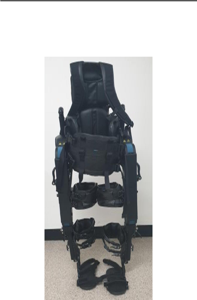
User’s Manual http://www.exoatletasia.com 3.8. Appearance and function 3.8.1. Main Body No. 1 Name Emergency stop Function In the event of an emergency, the button can be used to button stop the operation of the device. It is a handle that an assistant can hold when supporting 2 Handle 3 4 Thigh fastener. Shank binding. 5 Insole 6 Stop button 7 Shoulder straps 8 Corset 9 Cam levers ExoAtletⓇ II the product. It is a device that can fix the user's thighs.
User’s Manual http://www.exoatletasia.com 3.8.2. Remote control crutch : A left / right 1 set is provided as a crutch for supporting the patient's body. ➏ ➐ No. 1 Name display Run / Stop 2 button(Left button) Mode change 3 button Function A screen to check the mode or connection status of the product. Button used to instruct the operation of the product or to stop the device in operation. Button to select the operation of the product.
User’s Manual http://www.exoatletasia.com 3.8.3. Components 1) Body charger set (I-type socket) : Adapter set for charging the main body battery (complied with EN/IEC 60950-1) 2) Smart car battery charger set(C-type USB) : Adapter set to charge the smart crutches battery (complied with EN/IEC 60950-1) 3.8.4. Sold separately 1) Tablet PC set: A portable PC that installs an application to run products, and includes an adapter. (complied with EN/IEC 60950-1) ExoAtletⓇ II 20 / 84 Ver 1.0 (2019.03.29.
User’s Manual http://www.exoatletasia.com 3.9. Operating Environment - Temperature: 10 ℃ ~ 40 ℃ - Relative humidity: 20 % ~ 80 % (Non-condensing) - Pressure: 70.0 KPa ~ 106.0 KPa - Altitude: Less than 2,000 m 3.10. Storage Environment - Temperature: +5 ℃ ~ 40 ℃ - Relative humidity: ≤ 80 % (Non-condensing) - Pressure: 50 kPa ~ 106 kPa 3.11. Transportation condition Caution 1 2 Before carry the device, separate all components and carry them in the designated box packed with buffer.
User’s Manual http://www.exoatletasia.com 3.12. Symbol (Include safety sign) The following symbols describe the symbols used in the accessory document, product exterior, and product packaging. Read the product carefully before use and follow the instructions.
User’s Manual No Symbol 11 12 13 Explanation General mandatory action sign Ban http://www.exoatletasia.com Position - User’s manual - User’s manual (Safety sign) The risk of fingers can pinch. - Moving part - charge terminal 14 Direct current (D.C.
User’s Manual No Symbol http://www.exoatletasia.com Explanation Position 21 Direction of load - Product packaging 22 Fragile, handle with care - Packaging label 23 Stand-by 24 - On the product’s power button Authorized representative in the European Community - Product label and Packaging label - Product label and 25 EU CERTIFICATION MARK Packaging label - User’s manual ExoAtletⓇ II 24 / 84 Ver 1.0 (2019.03.29.
User’s Manual http://www.exoatletasia.com 3.13. Label 3.13.1. Main Body 3.13.2. Remote control crutch 3.13.3. Packaging label ExoAtletⓇ II 25 / 84 Ver 1.0 (2019.03.29.
User’s Manual http://www.exoatletasia.com 4. Size adjustment 4.1. Shoe insole/Shoe sole 4.1.1. Choose the relevant insole/sole from the set and place it on the bracket. [Figure 1] 4.1.2. Fasten the screws with the enclosed driver. In case of using soles, you should use longer screws from the tools kit and fasten the screws from the other side. [Figure 2] ExoAtletⓇ II 26 / 84 Ver 1.0 (2019.03.29.
User’s Manual http://www.exoatletasia.com 4.2. Calf length adjustment 4.2.1. As shown in [Figure 3], Pull out and loosen two cam levers. 4.2.2. As shown in [Figure 4], Adjust sizes by the size lines and push down the cam levers to fix them. [Figure 3] [Figure 4] 4.3. Calf depth adjustment 4.3.1. As shown in [Figure 5], Pull out and loosen the cam lever. 4.3.2. As shown in [Figure 6], Adjust sizes by the size lines and push down the cam lever to fix it.
User’s Manual http://www.exoatletasia.com 4.4. Thigh length adjustment 4.4.1. As shown in [Figure 7], Pull out and loosen the cam lever. 4.4.2. As shown in [Figure 8], Adjust sizes by the size lines and push down the cam lever to fix it.If the lower drive is not positioned right it will be difficult to fix cam lever. [Figure 7] [Figure 8] 4.5. Thigh depth adjustment 4.5.1. As shown in [Figure 9], Pull out and loosen the cam lever. 4.5.2. Adjust sizes by the size lines. 4.5.3.
User’s Manual http://www.exoatletasia.com 4.6. Pelvic floor depth control 4.6.1. As shown in [Figure 11], Remove the previous back pad. Place the required back pad. [Figure 11] [Figure 12] 4.7. Adjust pelvic floor area 4.7.1. As shown in [Figure 13], Pull out and loosen two cam levers. 4.7.2. As shown in [Figure 14], Pull out the lever. Rotate the lever to adjust the desired width (rotating clockwise widens the pelvis). lever [Figure 13] ExoAtletⓇ II [Figure 14] 29 / 84 Ver 1.0 (2019.03.29.
User’s Manual http://www.exoatletasia.com 4.7.3. As shown in [Figure 15], Adjust sizes by the size lines and push down two cam levers to fix them. Repeat the same procedure from the other side. [Figure 15] Note: it is necessary to adjust both sides similar. 4.8. Hip Abduction / Adduction 4.8.1. Pull out and loosen two cam levers. 4.8.2. As shown in [Figure 16], Adjust the right angle by rotating cylindrical handle and then push down two cam levers to fix them.
User’s Manual http://www.exoatletasia.com 4.9. Ankle joint angle adjustment 4.9.1. As shown in [Figure 17], Pull out and loosen the cam lever 4.9.2. As shown in [Figure 18], Adjust sizes by the size lines and push down cam lever to fix it. Repeat the same procedure from the other side. [Figure 17] [Figure 18] Note: it is necessary to adjust both sides similar. 4.10. Height adjustment of back 4.10.1. As shown in [Figure 19], Pull out and loosen two cam levers. [Figure 19] ExoAtletⓇ II 31 / 84 Ver 1.
User’s Manual http://www.exoatletasia.com 4.10.2. As shown in [Figure 20], Adjust the size according to the height of the patient and then push down two cam levers to fix them. [Figure 20] ExoAtletⓇ II 32 / 84 Ver 1.0 (2019.03.29.
User’s Manual http://www.exoatletasia.com 5. Wearing 5.1. Precautions before wearing 5.1.1. Exoskeleton should be adjusted strictly according to the body sizes of the pilot. 5.1.2. Incorrect body size measurement and incorrect size adjustment of exoskeleton can cause malfunctioning. 5.1.3. Confirm if the exoskeleton is adjusted at the same size in both sides. 5.1.4. Do not let the belts or straps fasten the body too tightly 5.1.5. Make sure that pilot’s toes are not bended in the shoes. 5.2.
User’s Manual http://www.exoatletasia.com 5.3.6. Change the tightness of the buttock belt using bindings on the bottom side of the belt – they should be set on the same size (you can check it by the numbers). 5.4. Transferring to exoskeleton 5.4.1. Check that exoskeleton sits on the stool firmly (thighs are parallel to the surface). ExoAtletⓇ II 34 / 84 Ver 1.0 (2019.03.29.
User’s Manual http://www.exoatletasia.com 5.4.2. Position the wheelchair on the right sideclosely to the knee joint of the exoskeleton (in case of right-handed pilot). 5.4.3. Place right hand on the far (right) thigh of the exoskeleton andtransfer the body. At the same time assistant should keepexoskeleton firmly in order not to let it sway. 5.4.4. If the pilot cannot moveto the exoskeleton by himself, one assistant can transfer the pilot to the device.
User’s Manual http://www.exoatletasia.com 5.5. Putting on exoskeleton 5.5.1. If you use insoles put on shoes. After finished carefully check the fingers of the patient to prevent bending of the fingers. Proceed from the both sides. 5.5.2. If you use soles fix patients leg with three straps. First release the strap, insert the metal binding into relevant hole and fix it. Straps should be fixed very tight in order not to allow undoing. Proceed from the both sides. ExoAtletⓇ II 36 / 84 Ver 1.0 (2019.03.
User’s Manual 5.5.3. http://www.exoatletasia.com Fix shank bindings using two straps. It is necessary to put soft pads under the straps in order to prevent damaging of the patient’s skin.Proceed from the both sides. ExoAtletⓇ II 37 / 84 Ver 1.0 (2019.03.29.
User’s Manual 5.5.4. http://www.exoatletasia.com Fix thigh bindings using two straps. It is necessary to put soft pads under the straps in order to prevent damaging of the patient’s skin. Proceed from the both sides. 5.5.5. ExoAtletⓇ II Fix corset using two belts from each side and put on shoulder straps. 38 / 84 Ver 1.0 (2019.03.29.
User’s Manual http://www.exoatletasia.com 6. Operation 6.1. Preparation before use 6.1.1. Make sure you have all the components. 6.1.2. Make sure that the Tablet PC and the application running on the product are installed. 6.1.3. Press the power button on the main unit to check if power is supplied normally. 6.1.4. Make sure that the straps that secure the torso and legs of the pilot are secure. 6.2. General functions 6.2.1.
User’s Manual http://www.exoatletasia.com 6.3. Emergency Stop Function In case of malfunction or other unexpected situation it is possible to immediately stop exoskeleton. For that purpose, use red switch on the right handle of exoskeleton. After pressing exoskeleton will immediately stop its motion and freeze in current position until the switch will be released and then “OK” button will be pressed in a pop-up screen on Tablet PC.
User’s Manual http://www.exoatletasia.com While emergency stop is active motors will allow exoskeleton to slowly get down. In this case it is necessary to place a chair under the patient and then press a “release” button near the hip drives to allow exoskeleton to sit on the chair. After that it is necessary to bend knees of the patient pressing “release” button near the shin drives. 6.4. How to clean and store after use 6.4.1.
User’s Manual http://www.exoatletasia.com 7. Tablet PC operating 7.1. Starting Software already runs on the Tablet PC. You can check the connection to the exoskeleton by looking at the indicator in the top left side of the screen (red light on Figure 39 shows that there is no connection). Figure 39 Turn on exoskeleton and wait for connection to be set (green light on Figure 40 shows that exoskeleton is connected). Figure 40 Input login doctor and password doctor and then press Authorization button.
User’s Manual http://www.exoatletasia.com Figure 41 After successful authorization main menu will be shown. Figure 42 Press on the logo in the top left side of the screen. You will see the list of the sections: Training, Service, Settings, About, Exit. ExoAtletⓇ II 43 / 84 Ver 1.0 (2019.03.29.
User’s Manual http://www.exoatletasia.com Figure 43 7.2. Trainings Figure 44 In the Trainings section you can open all the finished training and see the basic information about it (more details in 8.2.2). You can exit training by pressing arrow button in the top left side of the screen (See Figure 45) and then you will return to the Trainings screen. ExoAtletⓇ II 44 / 84 Ver 1.0 (2019.03.29.
User’s Manual http://www.exoatletasia.com Figure 45 7.2.1. Starting training Press + button in the bottom right side of the screen to create new training session. Figure 46 ExoAtletⓇ II 45 / 84 Ver 1.0 (2019.03.29.
User’s Manual http://www.exoatletasia.com 1) Pilots Choose the pilot to train with by pressing on his name. Currently only default pilot is available. Figure 47 2) Parameters of training Enter current values of pulse, blood pressure, saturation by pressing the buttons with arrow in the right side from the value. Then press “OK”. You will get to the training screen. Warning: please pay attention that device does not measure these values by itself.
User’s Manual http://www.exoatletasia.com 7.2.2. Main training screen Main training screen consists of the sections: - Information: describes the current doctor and pilot that were chosen, vital values that were input and statistics of the training. - Training – consists of the motion buttons, different settings buttons and remote control switch. - Events – shows the log of the events that were performed during training. Before pressing “Start training” button all the buttons are unavailable.
User’s Manual http://www.exoatletasia.com 1) Settings After pressing “Settings” button you will get to the Settings screen (more details in 8.2.3). Warning: you should carefully check that shank length and thigh length in the settings are similar to the ones that set on exoskeleton. Otherwise it may result in incorrect walking and even injury of the patient because exoskeleton calculates the walking pattern according to these values. 2) Stop training After training you should press “Stop training” button.
User’s Manual http://www.exoatletasia.com Figure 52 3) Motion buttons Available motion buttons depend on the current pose of the exoskeleton. There are 3 available poses: ① Undefined pose – when limbs of the exoskeleton are not in standard sitting or standing pose. If you moved some of the limbs before turning on exoskeleton, it will probably be in this pose. In this pose only “Pose reset” (more details in 8.2.2.3.5) motion is available (see Figure 53). Figure 53 ExoAtletⓇ II 49 / 84 Ver 1.0 (2019.03.
User’s Manual http://www.exoatletasia.com ② Sitting pose – the pose when limbs of the exoskeleton are in standard sitting position. In this pose motions “Get up” (more details in 8.2.2.3.2) and “Pose reset” (more details in 8.2.2.3.5) are available (see Figure 54). Figure 54 ③ Standing pose – the pose when limbs of the exoskeleton are in standard standing position. In this pose motions “Sit down” (more details in 8.2.2.3.1), “Walking in place” (more details in 8.2.2.3.4), “Walking” (more details in 8.2.
User’s Manual http://www.exoatletasia.com ④ Sit down In accordance with the selected settings (more details in 8.2.4.4) after pressing “Sit down” button exoskeleton will perform 3 beeping sounds and then will get into sitting pose. When finished, it will beep one more time to show that device is ready for the next motion. ⑤ Getup In accordance with the selected settings (more details in 8.2.4.
User’s Manual http://www.exoatletasia.com ⑦ Walking on place In accordance with the selected settings (more details in 8.2.4.2) after pressing “Walking in place” button exoskeleton will perform 3 beeping sound and then will initiate the chosen mode. Warning: before initiating walking carefully read the “Motion setting” clause.
User’s Manual http://www.exoatletasia.com Figure 58 5) Motion parameters After pressing “Motion parameters” button you will get to “Motion Parameters” screen (more details in clause 8.2.4) 6) Leaving note If you will press on one of the events in “Events” section, you will open “Notes” window.
User’s Manual http://www.exoatletasia.com Figure 59 7.2.3. Settings After pressing «Settings» button settings screen appears. You should input at least shank length and thigh length to be able to initiate motions of the exoskeleton. Press “Save” button in top right side of the screen to save current parameters. Press back arrow in the top left side of the screen to close settings screen without keeping the changes.
User’s Manual http://www.exoatletasia.com You can write all the settings that are available to adjust on the exoskeleton or may be useful for the training purpose: 1) Insole Size. min = 33, max = 45, step = 1. You can leave it blank if soles are installed on the device. 2) Sole Size. Available values: 36-38, 39-41, 42-45, -. You can leave it blank if insoles are installed on the device. 3) Shank length – min = 420, max = 590, step = 5. 4) Foot eversion - min = 0, max = 5, step = 1.
User’s Manual http://www.exoatletasia.com Figure 61 1) Walking After pressing “Walking” button you will get access to the parameters of walking (See Figure 62). Figure 62 Press “Back” button in top left side of the screen to leave the settings without any changes. You can adjust various parameters: ① Pause between steps – parameter defines the time between ending one step and starting another step (available only in “Continuous mode”). Min = 0, max = 1 s, step = 0.1 s. ExoAtletⓇ II 56 / 84 Ver 1.
User’s Manual http://www.exoatletasia.com ② Duration of the step - parameter defines the time of performing one step. Min = 1.2 s, max = 2 s, step = 0.1 s. ③ Step height – parameter defines the height that exoskeleton feet will reach during every step. Min = 10 cm, Max = for low patients 20 cm, for middle patients 22 cm, for high patients 25 cm. Step = 1 cm. ④ Step length – parameter defines the length of one exoskeleton’s step.
User’s Manual http://www.exoatletasia.com 2) Mode. After pressing on “Initiation mode” button you will get access to three modes (see Figure 64): Figure 64 Continuous mode: the mode when walking initiates immediately after pressing “Walking” button on Training screen – after 3 beeps exoskeleton starts continuous walking starting from the left leg.
User’s Manual http://www.exoatletasia.com Figure 65 Step-by-step mode: after pressing “Walking” button there will 1 short beep showing that exoskeleton got into step-by-step walking mode. In order to make one step you should press the button on the left handle of exoskeleton. After 3 beeping signals exoskeleton will make a first step from the left leg and will stop in this pose. You will be able to see the chosen mode in the bottom side of “Training” section.
User’s Manual http://www.exoatletasia.com Figure 66 After pressing “Walking” button on Training screen exoskeleton will perform 3 beeping signals and then will wait for the patient to start movement. You will be able to see the chosen mode in the bottom side of “Training” section. Patient should try to move his left leg forward to initiate first step. If patient exceeds the chosen effort limit exoskeleton will immediately make a step with left leg and then stop.
User’s Manual http://www.exoatletasia.com Figure 67 ① Pause between steps – parameter defines the time between ending one step and starting another step (available only in “Continuous mode”). Min = 0, max = 1 s, step = 0.1 s. ② Duration of the step - parameter defines the time of performing one step. Min = 1.2 s, max = 2 s, step = 0.1 s. ③ Step height – parameter defines the height that exoskeleton feet will reach during every step.
User’s Manual http://www.exoatletasia.com ⑦ Initiation mode – it is possible to choose three different modes – continuous mode, step-by-step mode, by effort mode. Their operation is similar to “Walking” modes description (more details in 8.2.4.1). The only difference is that when walking on place is stopped in Step-by-Step or By effort mode exoskeleton will not make a final step and will immediately get into standing pose awaiting for the next motion.
User’s Manual http://www.exoatletasia.com Figure 69 6) Saving changes If you will press “Save” button on one of the movement settings all the changes will be kept and you will get back to the motion parameters screen. You will see that motion was changed by an orange tag in the bottom side of the button (see Figure 70). Pay attention, that if you will change parameters of only one of the movements tag will appear only below the exact button. Figure 70 ExoAtletⓇ II 63 / 84 Ver 1.0 (2019.03.29.
User’s Manual http://www.exoatletasia.com 7.2.5. Errors During exoskeleton operating some errors may appear (for example, in case of not correct transition of the mass of the patient). In that case a message will appear on the screen. You can reset the error pressing “Ok” button. In most of situations after it you will have to return exoskeleton to the standard pose using “Pose reset” button.
User’s Manual http://www.exoatletasia.com Figure 72 7.3. Service Service section allows user to create backup file and send it via e-mail. It may be needed for a technical support. After pressing “Make a backup” button exoskeleton will start to create a backup file and it will take some time. Figure 73 During creating of the backup file some errors may appear (for example, in case of lack of connection between Tablet PC and exoskeleton). In that case you will see an error message on the screen.
User’s Manual http://www.exoatletasia.com Figure 74 7.4. Settings Settings section allows user to connect Tablet PC to a wi-fi or change the language. Figure 75 ExoAtletⓇ II 66 / 84 Ver 1.0 (2019.03.29.
User’s Manual http://www.exoatletasia.com 7.5. About About section shows user the current version of the Tablet PC software. This information may be helpful for a technical support. Figure76 7.6. Exit Pressing “Exit” button will return user to the log screen (see 8.1). ExoAtletⓇ II 67 / 84 Ver 1.0 (2019.03.29.
User’s Manual http://www.exoatletasia.com 8. ExoCrutch operation 8.1. ExoCrutch structure ExoCrutch contains of 6 main components: 8.1.1. “Turn ON” button. 8.1.2. LED-indicator. 8.1.3. Charging port (USB type-C) 8.1.4. Display. 8.1.5. “Mode change” button. 8.1.6. “Action” button. Figure 77 Figure 78 Figure 79 ExoAtletⓇ II Figure 80 68 / 84 Ver 1.0 (2019.03.29.
User’s Manual http://www.exoatletasia.com Display have 4 main elements: - ExoCrutch charge indicator. - Exoskeleton charge indicator. - Exoskeleton current condition indicator. - Selected motion/mode. Figure 81 8.2. ExoCrutch available motions: Icon Not defined pose Value Pose reset to sitting pose Pose reset to standing pose Sitting pose Standing up (Low) Standing up (Middle) Standing up (High) Standing pose Sitting down ExoAtletⓇ II 69 / 84 Ver 1.0 (2019.03.29.
User’s Manual http://www.exoatletasia.com Walking in place (high step) Walking in place (low step) Walking (short and high step) Walking (short and low step)) Walking (middle and high step) Walking (middle and low step) Walking (long and high step) Walking (long and short step) 8.3. ExoCrutch operation 8.3.1. Turning ExoCrutch on 1) Turn exoskeleton on (see clause 7.1.1). 2) Start training sessions with the pilot on Tablet PC (More details in 8.2.
User’s Manual http://www.exoatletasia.com Note: if remote control operation is not activated on the Tablet PC you will see an error icon on the display after ExoCrutch initialization. Figure 83 4) After successful initialization you will see a working screen. Figure 84 8.4. ExoCrutch operation 8.4.1. Depending on the current pose you have different available motions (see clause 9.2 for reference). 8.4.2. Using “Mode change” button choose the desirable motion. ExoAtletⓇ II 71 / 84 Ver 1.0 (2019.03.29.
User’s Manual http://www.exoatletasia.com Figure 85 8.4.3. Confirm the motion by pressing “Mode change” button at least for 1 second. You will see a green frame around the selected motion. Figure 86 Warning: you should confirm motion only when you change the desirable motion. If you walked and then pressed stop it is not necessary to confirm the motion again if you didn’t change it. 8.4.4. Press “Action” button to execute selected mode/motion.
User’s Manual http://www.exoatletasia.com 8.5. Error reset Sometimes an error may appear during walking (for example because of the spastics of the patient). In this situation exoskeleton will start to provide error signals and you will see an error message on the display of ExoCrutch. Figure 87 8.5.1. Press “Action” button to reset error. Error signals will stop. 8.5.2. Choose the desirable pose for exoskeleton to come to.
User’s Manual http://www.exoatletasia.com 9. Charging the battery 9.1. Charging exoskeleton 9.1.1. Connect the charger to the port on the right side of the exoskeleton. Figure 88 9.1.2. Plug the charger into the outlet. Lights will turn red on the chargerand exoskeleton and LED bar on the exoskeleton will show the current charge (1 bar = 20%). Figure 89 ExoAtletⓇ II 74 / 84 Ver 1.0 (2019.03.29.
User’s Manual http://www.exoatletasia.com 9.1.3. When charging will be finished LED bar will be full and lights will turn green.You can pull the plug out. Note: it is forbidden to use any other charger except the one that comes with the device. Note: it is forbidden to charge exoskeleton with the patient inside the device. 9.2. Charging Tablet PC 9.2.1. Tablet PC has a port on the bottom side so it charges from exoskeleton. Figure 90 9.2.2.
User’s Manual http://www.exoatletasia.com 9.3. Charging ExoCrutch 9.3.1. Connect the charger to the port on the front side of the device. Figure 92 9.3.2. Plug the charger into the outlet. Light will turn red on the front side of the device – ExoCrutch is now charging. Figure 93 9.3.3. When charging is finished light will turn green so you can unplug the charger. ExoAtletⓇ II 76 / 84 Ver 1.0 (2019.03.29.
User’s Manual http://www.exoatletasia.com 10. Trouble Shooting 10.1. When charging Symptom Checklist Check that the charger is connected to the charging Solution method Connect the charger correctly to the charging terminal. Battery charging terminal correctly. Check if the charging light is error turn on. your dealer. If the battery is not charged, please Please check the battery state of charge the battery. If it doesn't work charge.
User’s Manual http://www.exoatletasia.com 10.3. In operating Symptom If a beep sounds after setting your posture Checklist Solution method If the postures are not fully engaged, a beep may sound. Please set the posture again from the Please check if the posture is set beginning. properly. If noise occurs The motor may make a noise The motor may make a noise during during operation during operation. operation.
User’s Manual http://www.exoatletasia.com 11. Maintenance 11.1. Maintenance - Clean the equipment and the Crutch according to the specified cleaning method with the power off. - During use, the user or responsible organization must perform regular check-up or maintenance activities. If the operation of the device is suspicious or the device does not operate normally during use, contact our customer service center for action.
User’s Manual http://www.exoatletasia.com 12. Appendix 12.1. Product quality assurance policy - This product is manufactured by ExoAtlet Asia Co., Ltd. Compensation standards for product repairs and exchanges are subject to the "Consumer Injury Compensation Rules" of the regulatory authorities. - ExoAtlet Asia Co., Ltd. warrants that the design, development, and manufacture of this device is in reasonable control. [Manufacturer]: ExoAtlet Asia Co., Ltd.
User’s Manual http://www.exoatletasia.com 12.2. Instructions and manufacturer declarations 12.2.1. Electromagnetic emissions The ExoAtletⓇⅡ is intended for use in the electromagnetic environment specified below. The customer or the user of the ExoAtletⓇⅡ should assure that it is used in such an environment. Emissions test RF emissions CISPR 11 RF emissions CISPR 11 Compliance Electromagnetic environment – guidance The ExoAtletⓇⅡ uses RF energy only for its internal function.
User’s Manual http://www.exoatletasia.com 12.2.2. Electromagnetic IMMUNITY The ExoAtletⓇⅡ is intended for use in the electromagnetic environment specified below. The customer or the user of the ExoAtletⓇⅡ should assure that it is used in such an environment. IMMUNITY test IEC 60601 test level Compliance level Electrostatic discharge (ESD) Floors should be wood, concrete or ± 6 kV contact ceramic tile.
User’s Manual http://www.exoatletasia.com 12.2.3. Electromagnetic IMMUNITY – Non-LIFE-SUPPORTING equipment or system The ExoAtletⓇⅡ is intended for use in the electromagnetic environment specified below. The customer or the user of the ExoAtletⓇⅡ should assure that it is used in such an environment.
User’s Manual http://www.exoatletasia.com 12.2.4. Recommended separation distance between this system and mobile RF communication devices - Non-LIFE-SUPPORTING equipment or system Recommended separation distances between portable and mobile RF communications equipment and the ExoAtletⓇⅡ The ExoAtletⓇⅡ is intended for use in an electromagnetic environment in which radiated RF disturbances are controlled.
FCC Information to User This equipment has been tested and found to comply with the limits for a Class B digital device, pursuant to Part 15 of the FCC Rules. These limits are designed to provide reasonable protection against harmful interference in a residential installation. This equipment generates, uses and can radiate radio frequency energy and, if not installed and used in accordance with the instructions, may cause harmful interference to radio communications.