
User's Manual


Mobile WiMAX Indoor RAS SPI-2210 System Description/Ed.07
© SAMSUNG Electronics Co., Ltd. IX
LIST OF FIGURES
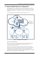
Figure 1.1 Mobile WiMAX Network Configuration .................................................................. 1-4
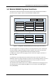
Figure 1.2 Configuration of Mobile WiMAX System Functions (Based on Profile C).............. 1-6
Figure 2.1 IPv4/IPv6 Dual Stack Operation ............................................................................ 2-8
Figure 2.2 SMIR Configuration............................................................................................. 2-18
Figure 2.3 SMIR Configuration (SMIR-A is added)............................................................... 2-19
Figure 2.4 Structure of Indoor SPI-2210 Interface................................................................ 2-20
Figure 2.5 Protocol Stack between NEs............................................................................... 2-21
Figure 2.6 Protocol Stack between Indoor SPI-2210 and WSM ........................................... 2-21
Figure 3.1 Internal Configuration of Indoor SPI-2210 ............................................................. 3-2
Figure 3.2 DMB Configuration................................................................................................ 3-3
Figure 3.3 RFB Configuration................................................................................................. 3-7
Figure 3.4 PDP-PIR Configuration ....................................................................................... 3-10
Figure 3.5 Power Structure....................................................................................................3-11
Figure 3.6 Fan and Related Devices.................................................................................... 3-12
Figure 3.7 Radiation Structure of Indoor SPI-2210............................................................... 3-13
Figure 3.8 I/O Module Configuration .................................................................................... 3-14
Figure 3.9 External Interfaces of Indoor SPI-2210 ............................................................... 3-15
Figure 3.10 Software Structure of Indoor SPI-2210.............................................................. 3-17
Figure 3.11 CC Block Structure ............................................................................................ 3-19
Figure 3.12 OAM Software Structure.................................................................................... 3-21
Figure 3.13 Interface between OAM Blocks ......................................................................... 3-22
Figure 3.14 SNMPD Block ................................................................................................... 3-23
Figure 3.15 OAGS Block...................................................................................................... 3-24
Figure 3.16 Web-EMT Block ................................................................................................ 3-25
Figure 3.17 CLIM Block........................................................................................................ 3-26
Figure 3.18 PAM Block......................................................................................................... 3-27
Figure 3.19 UFM Block......................................................................................................... 3-29
Figure 3.20 Loader Block ..................................................................................................... 3-30
Figure 3.21 ULM Block......................................................................................................... 3-32
Figure 3.22 OPM Block ........................................................................................................ 3-33
Figure 3.23 OSSM Block...................................................................................................... 3-34
Figure 3.24 OER/OEV Block ................................................................................................ 3-35
Figure 3.25 OCM Block ........................................................................................................ 3-36
Figure 3.26 RDM Block ........................................................................................................ 3-38
Figure 3.27 Redundancy Structure of OAM Block (MMA-S)................................................. 3-39