
User's Manual


Mobile WiMAX Indoor RAS SPI-2210 System Description/Ed.07
© SAMSUNG Electronics Co., Ltd. 3-15
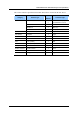
(Continued)
Board Name Quantity Function
RJIM 1 RJ-45 IO Module
RJ-45 connector cable termination stiffener (Optional Item)
GPSM 1 GPS IO Module
GPS antenna cable termination stiffener
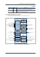
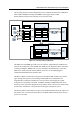
3.2.6 External Interface Structure
The layout of indoor SPI-2210 interfaces is as shown in the figure below:
Figure 3.9 External Interfaces of Indoor SPI-2210
-48 VDC
PDP-PI
R
FE for UDE
TTL for Form C control
RS-485 or others from/to Rectifier
LVTTL for TDD Out
Analog to temperature sensor
Open/Short for UDA
Open/Short from FCM
FE from/to AICU
FE to Consol
RS-232 for Debug port
From GPS Ant
Samsung Digital I/Q and OAM
from/to MRA-S
6Tx (2Tx x 3Sector) ports to Ant.
6Rx (2Rx x 3Sector) ports from Ant.
RF output monitoring
RS-232 for Debug
External Alarm
&
Control
MEI
MM
A
-S
Main Processing
Clock Processing
RS-232 for Debug-0
RS-232 for Debug-1
Samsung Digital I/Q and OAM
from/to MRU-2
Baseband
Processing
Samsung Digital
I/Q and OAM path
MR
A
-S
Power
conversion &
Distribution
Open/Short to 4fans
Open/Short to MEI
FCM
Internal Fan
Alarm & Control
DC Power to TTLNA
Alarm & Control from/to TTLNA
FE from/to AICU
TTLNA
Power feed/
Alarm & Control
A
ICU
6Rx (2Rx x 3Sector) ports
from antenna
MRR
Received RF
Processing
Samsung Digital
I/Q and
OAM
p
ath
MRU-2
RF Processing
FE or GE from/to ACR
FE/GE Network
Interface