
User's Manual


Mobile WiMAX Indoor RAS SPI-2210 System Description/Ed.07
© SAMSUNG Electronics Co., Ltd. 3-22
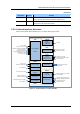
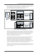
The following interface structure diagram shows the communication between OAM blocks.
Main OAM and EMI are running on the MMA-S that support master OAM.
Board OAM is running on the remaining lower processor board.
Figure 3.13 Interface between OAM Blocks
The EMI carries out SNMP agent and web server function, and provides the OAM interface
between the management system (WSM, Web-EMT and CLI Terminal) and the indoor SPI-
2210 by providing the IMISH. Then, to access the indoor SPI-2210 directly via the Web-
EMT or the console terminal and the authority allowance via the PAM (Pluggable
Authentication Module) block should be done.
The Main OAM is located in the main processor. The Main OAM communicates with the
upper management system by interworking with the EMI block and distributes the
Programmable Loading Data (PLD) to the lower processors by managing the system
configuration as the format of the PLD. In addition, the Main OAM performs the role of
the Image Server (IS) and the Registration Server (RS), collects and saves the statistics data
and the failure information, and reports them to the upper management system.
The Board OAM is located in the lower processor. The Board OAM collects the failure and
the statistics data of each board, reports them to the Main OAM and monitors the software
process of each board.
DDI
IF
M
MDS
Main Processo
r
Main OAM
Software
Entity
IPC
A
PI
A
PI
Shared Memory
OCM
RDM
UFM OPM
Loade
r
ULM
EMI
Web-EMT
WSM
Image Server
WSM
SFTP
SNMPv 2c/
SNMPv3
Board OAM
UFM OPM
Loade
r
ULM
OSSM
Board Processo
r
Software
Entity
IPC
A
PI
A
PI
Shared Memory
M
D
S
-
…
HTTP
s
SSH
Console
Terminal
CLIM
P
A
M
OSSM
OER/OEV
MDS
OAGS/SNMPD
Web-EMT