
User's Manual

CHAPTER 4. Message Flow
4-26
© SAMSUNG Electronics Co., Ltd.
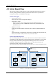
4.3 Alarm Signal Flow
The detection of failures in the SPI-2213 can be implemented by hardware interrupt or
software polling method. The failures generated in the SPI-2213 are reported to the
management system via the SNMP trap message.
Failure Alarm Types
y System Failure Alarms
Time Sync Fail, Fan Fail, Temperature High, etc.
y Board Failure Alarms
− Hardware Failure Alarms: FUNCTION FAIL, BOARD DELETION, etc.
− Software Failure Alarms: COMMUNICATION FAIL, PORT DOWN, CPU
OVERLOAD, etc.
y RRH Failure Alarms
LOW GAIN, OVER POWER, VSWR FAIL, PLL UNLOCK, RRH INTERFACE
FAIL etc.
y UDA
6 alarm input ports are supported for the rectifier alarm. Main AC Fail, Rectifier Fail,
Battery Fail, Cabinet Fan Fail, Heater Fail, Environment Alarm
Failure Report Message Flow
The main OAM (UFM) collects the failures detected from each board and UDA interface
of the SPI-2213 and notifies them to the management system. At this time, it only reports
the upper failure information by using the failure filtering function. If it receives the
command to inhibit the report for a specific failure or all system failures from the
management system, it does not report the failure report.
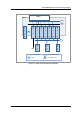
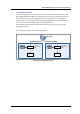
The flows for the failure detection and the report message are as shown in the figures below:
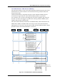
Figure 4.17 Alarm Signal Flow of SPI-2213
SPI-2213 SPI-2213
WSM
(SNMP Manage)
MMA-G
MRA-F
#0~5
MEI-B
RRH
#0~2
Alarm detection
Alarm filtering
Alarm Report
(SNMP trap)
Alarm detection
Alarm filtering
Alarm Report
(SNMP trap)
MMA-G
MRA-F
#0~5
MEI-B
RRH
#0~2