
User's Manual


CHAPTER 3. SPI-2213 Architecture
3-6
© SAMSUNG Electronics Co., Ltd.
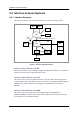
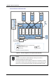
The DMB is configured as shown in the figure below:
Figure 3.3 DMB Configuration
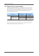
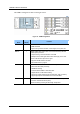
Board
Name
Quantity
(Sheet)
Function
MBB-F 1 Mobile WiMAX base station Backplane Board-Flexible
- DMB backboard
- Signal routing function for traffic, control signal, clock, power, etc.
MMA-G 1 Mobile WiMAX base station Main control board Assembly-General
- Main system processor
- Call processing, resource allocation and OAM
- Reception of the GPS signal and creation and supply of the clock
- Alarm collection and report to the upper
- Supports FE/GE interface with ACR
- Non-volatile memory support
MRA-F Max. 6 Mobile WiMAX base station RAS board Assembly-Flexible
- Subscriber data traffic processing
- OFDMA Processing
- 1Carrier/1Sector MIMO or 4T4R with CDD
- ‘Digital I/Q and C & M’ data formatting
- Supporting optical interfacing with the RRH (E/O, O/E conversion)
- Supporting loopback tests between the DU and the RRH
MEI-B 1 Mobile WiMAX base station External Interface board assembly-Basic
- Provides User Defined Alarm (UDA)
- Alarm monitoring including fan alarm/high temperature
DMB
MRA-F(5)
MRA-F(4)
MRA-F(3)
MRA-F(2)
MRA-F(1)
MRA-F(0)
MMA-G
MEI-B
DMB