
User's Manual


CHAPTER 3. SPI-2213 Architecture
3-10
© SAMSUNG Electronics Co., Ltd.
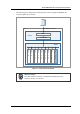
The RRH is an RRH that integrates the RAS transceiver, power amplifier, TDD switch, and
filters in a single module.
In the case of downlink signals, the RRH converts baseband signals received through the
‘Digital I/Q and C & M’ interface from the MRA-F into Optic to Electrical (O/E).
The converted signals undergo Digital to Analog Conversion (DAC) to be converted to
analog RF signals, and then are amplified through the current amplification process.
Amplified signals are sent to the antenna via the filter part.
In the case of uplink signals, the frequency of the signals received through the RRH filter
part is lowered by Low Noise Amplifier (LNA). The Analog to Digital Conversion (ADC)
process converts these signals to baseband signals. The baseband signals are in the ‘Digital
I/Q and C & M’ format, and undergo E/O conversion to be sent to the MRA-F.
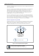
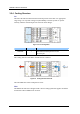
Network Configuration Using the RRH
The RRH cannot operate on its own, but operates by being linked to the DU. The RRH is
highly flexible in its installation, and helps with setting up a network in a variety of
configurations depending on the location and operation method as shown below.
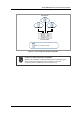
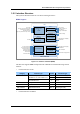
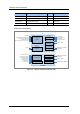
Figure 3.4 Sector Configuration Example Using RRH-2
Conditions for Sector Configuration Using RRH-2
2carrier supported by the RRH-2 must be a contiguous type.
α Sector
β Sector
γ Sector
2 Carrier/3 Sector
RRH-2 for 2Tx/2Rx or 4Tx/4Rx