
User's Manual


Mobile WiMAX RAS SPI-2213 System Description/Ed.02
© SAMSUNG Electronics Co., Ltd. 3-15
3.2.5 Interface Structure
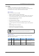
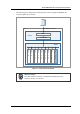
The layout of SPI-2213 interfaces is as shown in the figure below:
MIMO Support
Figure 3.10 Interfaces of SPI-2213 (MIMO)
The SPI-2213 supports MIMO and provides the administrator with the following external
interface.
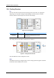
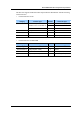
y External Interface of DU
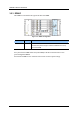
Category Interface Type Port No. Connector Type
2 1000 Base-X: SFP (LC) Simultaneous operation of
1000Base-X and 100/1000Base-TX
2 100/1000 Base-Tx: RJ-45
Backhaul
100/1000 Base-TX 4 RJ-45
GPS Antenna Analog RF 1 SMA
Rectifier Interface RS-485 or others 1 RJ-45
RRH interface Digital I/Q and C & M Max. 6 SFP (Single mode)
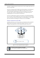
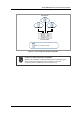
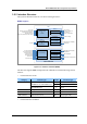
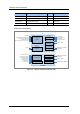
y External Interface of RRH-2
MMA-G
DU
MEI-B
Main Processing
Clock Processing
Power Filter
&
Distribution
DPM-FI
MRA-F
Digital I/Q
and C & M path
Baseband
Processing
External Alarm
&
Control
FE to UDE
RS-485 or others from/to Rectifier
FAN Alarm from FAN-FD 48
Open/Short for UDA
High Temp. Alarm form Temp. Sensor
-48 VDC
FE to Console
RS-232 for Debug port
From GPS Ant
Analog 10 MHz Output
RS-232 for Debug
Digital I/Q and C & M(Optic)
From/to RRH
RRH-2LB/RRH-2UB
E/O, O/E conversion
RET control
Digital I/Q and C & M(Optic)
from/to MRA-F
TDD Clock Output
AISG to RET motor @Antenna
Digital I/Q and
C & M path
E/O, O/E conversion
2Tx ports to Antenna
2Rx ports from Antenna
RF output monitoring
RS-232 for Debug
TDD Signal Output
-48 VDC input
DC Power to RET
RF Processing
Power Module