
User's Manual

Wirel
e
Version 1.0
5. Pin des
c
1.2 VDD
6.RESE
T
7. I2C_S
C
8. I2C_S
D
12, 24. G
R
13. BCK
14. LRC
K
15. DAT
_
16. DAT
_
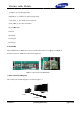
6. Installat
i
This modul
e
And the loc
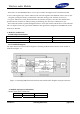
7. Brief s
ys
This radios
e
ss aud
i
c
ription
: 5V powe
r
T
# : it is us
e
C
L_S : I2C
D
A_S: I2C
R
OUND
K
_
W
_
X
i
on
e
must be i
n
ation of ins
t
s
tem block
d
system blo
c
i
o Mod
u
r
supply inp
u
e
d to 5V po
w
serial clock
data conne
c
n
stalled in a
t
allation is
a
Fig
u
d
ia
g
ram
c
k diagram i
Woofer
u
le
Sa
m
ut
w
er supply
i
connection
c
tion.
device and
n
a
s follows F
i
u
re 6-1 The
l
s as follow
s
Sou
n
m
sung Elect
i
nput.
.
n
ot allow th
i
gure 6-1.
l
ocation of i
n
s
figure 7-1
n
d Ba
r
ronics
e user to re
p
n
stallation
p
lace nor m
o
o
dify i
t
.
page 4 o
f
f
8