TFT-LCD MONITOR Chassis Degas SERVICE Model DS17BS* Manual TFT-LCD MONITOR CONTENTS 1. Precautions 2. Product Specifications 3. Disassembly & Reassembly 4. Alignment & Adjustments 5. Troubleshooting 6. Exploded View & Parts List 7. Electrical Parts List 8. Block Diagram 9. Wiring Diagram 10. PCB Layout 11. Schematic Diagrams 12.
1 Precautions Follow these safety, servicing and ESD precautions to prevent damage and to protect against potential hazards such as electrical shock. 1-1 Safety Precautions 1-1-1 Warnings 1. For continued safety, do not attempt to modify the circuit board. 2. Disconnect the AC power and DC Power Jack before servicing. 3. (READING SHOULD NOT BE ABOVE 0.5mA) When the chassis is operating, semiconductor heatsinks are potential shock hazards.
1 Precautions 1-2 Servicing Precautions WARNING: An electrolytic capacitor installed with the wrong polarity might explode. Caution: Before servicing units covered by this service manual, read and follow the Safety Precautions section of this manual. Note: If unforeseen circumstances create conflict between the following servicing precautions and any of the safety precautions, always follow the safety precautions. 1-2-1 General Servicing Precautions 1. 2. 3.
2 Product Specifications 2-1 Specifications Item Description LCD Panel TFT-LCD panel, RGB vertical stripe, normaly white, 17-Inch viewable, 0.264 mm pixel pitch Scanning Frequency Horizontal : 30 kHz ~ 81kHz (Automatic) Vertical : 56 Hz ~ 75 Hz (Automatic) Display Colors 16.2 M Maximum Resolution Horizontal : 1280 Pixels Input Video Signal Analog, 0.
2 Product Specifications 2-2 Pin Assignments Sync Type Pin No.
2 Product Specifications 2-3 Timing Chart This section of the service manual describes the timing that the computer industry recognizes as standard for computer-generated video signals. Table 2-1 Timing Chart Mode IBM VGA1/70 Hz VESA VGA2/70 Hz VGA3/60 Hz 640/72 Hz 640/75 Hz 800/56 Hz 800/60 Hz 640 x 350 720 x 400 640 x 480 640 x 480 640 x 480 800 x 600 800 x 600 fH (kHz) 31.469 31.469 31.469 37.861 37.500 35.156 37.879 A µsec 31.778 31.777 31.778 26.413 26.667 28.444 26.
2 Product Specifications Table 2-2 Timing Chart Mode IBM VESA VGA2/ 70 Hz VGA3/ 60 Hz 720 x 400 640 x 480 fH (kHz) 31.469 A µsec 1024/75 Hz 1280/60 Hz 1280/75 Hz 1280 x 1024 1280 x 1024 1024 x 768 (Analog) (Analog) 640/75 Hz 800/60 Hz 800/75 Hz 1024/60 Hz 640 x 480 800 x 600 800 x 600 1024 x 768 31.469 37.500 37.879 46.875 48.363 60.023 63.981 79.975 31.777 31.778 26.667 26.400 21.333 20.677 16.660 11.852 12.504 B µsec 3.813 3.813 2.032 3.200 1.616 2.092 1.219 1.
4 Alignments and Adjustments This section of the service manual explains how to use the RS232 JIG. This function is needed for AD board change and program memory (IC110) change. 4-1 Required Equipment The following equipment is necessary for adjusting the monitor: • Computer with Windows 95, Windows 98, or Windows NT. • MTI-2031 DDC MANAGER JIG 4-2 Automatic Color Adjustment To input video, use 16 gray or any pattern using black and white. 1.
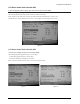
4 Alignments and Adjustments 4-6 Service Function Spec. 4-6-1 How to Display Service Function OSD 1. The value for brightness and contrast should be changed to zero. 2. Within 5 seconds, press the exit key. 3. Service function OSD will be displayed. If you want to disable the service function OSD, you will have to power off. Panel Information Software Version Check sum Figure 2. The example of service function OSD The service function OSD is based on a grid of 29 columns x 12 rows.
4 Alignments and Adjustments 4-6-3 How to Control Service Function OSD • After change the panel or lamp, you must reset service function OSD. • The case of panel change After changeing the panel, press the menu key within 5 seconds,. Then, panel Ch. No increases one step and the panel time information is reset to zero. Simultaneously, other information is reset to zero (Upper/Lower lamp, Panel cycle). Figure 4.
4 Alignments and Adjustments 4-6-5 Pixel shift and language selection change * Note : Use the '-' key to vary values for new pixel shift and country menu. 1. Pixel shift : on off - When a same picture is displayed with no change for an extended period of time, this function prevents the display panel from image sticking. * On for '0 x 01' with EEPROM 0x2E, Off for others; Always restart the monitor after EEPROM adjustment. - Motion path : see Figure 7.
4 Alignments and Adjustments DS17BS* Figure 8-2. Figure 8-3. Figure 9. Figure 9-1.
4 Alignments and Adjustments Memo 4-6 DS17BS*
3 Disassembly and Reassembly This section of the service manual describes the disassembly and reassembly procedures for the DS17BS* monitor. WARNING: This monitor contains electrostatically sensitive devices. Use caution when handling these components. 3-1 Disassembly Cautions : 1. Disconnect the monitor from the power source before disassembly. 2. Follow these directions carefully; never use metal instruments to pry apart the cabinet. 3. R/Cover opening jig : BH81-00001A 1.
3 Disassembly and Reassembly 6. Disconnect LVDS cable and inverter cable. 3-2 Replacement Order of Lamp Assemblies *Do not replace lamp for the LTM170EX-L01 panel. *Note : No speciflc color for the wire connector of panel lamp is required. You can change a connector assemble. 3-3 Reassembly Reassembly procedures are in the reverse order of disassembly procedures.
5 Troubleshooting Notes: 1. Before troubleshooting, setup the PC’s display as below. • Resolution: 1280 x 1024 • H-frequency: 48 kHz • V-frequency: 60 Hz 2. If no picture appears, make sure the power cord is correctly connected. 3. Check the following circuits. • No raster appears: SMPS PCB, Main PCB • 14V develop but no screen: Main PCB • 14V does not develop: SMPS PCB 4. If you push and hold the “EXIT” button for more than 5 seconds, the monitor automatically turns back to the factory preset.
5 Troubleshooting 5-2 No Video Power indicator is green. Does DC 5V appear at Pin 1, 2 and 3 of CN04? No Replace IC109 or check it’s related circuit. Yes 3 4 Does the pulse appear at Pin 74 and 75 of IC101? No 5 6 No 7 8 Yes Yes 1 Replace LCD panel. Does the pulse appear at Pin 126 and 127 of IC101? Does the pulse appear at Pin 122 of IC101? Yes Replace IC101. Does the pulse appear at Pin 8 and 10 of IC110? No Yes No Check IC102 and check it’s related circuit.
5 Troubleshooting WAVEFORMS 1 2 3 4 5 6 7 8 DS17BS* 5-3
5 Troubleshooting 5-3 No OSD There is video but no OSD. Press exit key for more than 5 seconds to do the factory preset. When pushing a front control button, does any change appear at Pin 16 and 17 of IC102? No Replace front control button. Yes Replace IC101 and check its related circuit.
7 Electrical Parts List You can search for updated part codes through CMS web site. URL : http://ecms. samsungelectronics. com/ 7-1 Main PCB Parts Loc. No. Code No. Description Specification Remarks CIS2 CIS3 CIS6 CIS7 CIS5 CIS4 CIS10 BN94-00479B 0202-001044 0202-001222 0204-001095 0204-001677 BN39-00395B BN39-00419A BN63-01079A ASSY PCB MAIN SOLDER-WIRE. SOLDER-WIRE FLUX THINNER FLUX LEAD CONNECTOR LEAD CONNECTOR GASKET DS17BS S63S-W3.0,S63S,D3,63Sn/37Pb,RS-107,RS60-1.2AA,D1.
7 Electrical Parts List Loc. No. C137 C138 C139 C140 C141 C142 C143 C144 C145 C146 C147 C148 C149 C150 C151 C152 C153 C154 C155 C156 C157 C158 C159 C160 C161 C162 C167 C168 C169 C170 C171 C172 C173 C174 C175 C176 C177 C178 C179 C180 C181 C182 C185 C186 C187 C188 C189 CIS1 CIS8 CN01 CN02 CN04 CN05 D101 D102 7-2 Code No.
7 Electrical Parts List Loc. No. D103 D104 D105 D106 D107 D108 D109 D110 D111 D112 D113 D115 FT101 FT102 FT103 FT104 FT106 FT107 FT108 FT109 FT110 IC101 IC102_SOCKET IC103 IC104 IC107 IC108 IC109 IC110 IC111 L101 L102 MP1.0 Q101 R100 R101 R102 R103 R104 R105 R106 R107 R108 R109 R110 R111 R112 R113 R114 R115 R116 R117 R118 R119 R120 DS17BS* Code No.
7 Electrical Parts List Loc. No. R121 R122 R123 R124 R125 R126 R127 R128 R129 R130 R131 R132 R133 R134 R135 R136 R140 R142 R143 R150 R151 R153 R154 R155 R156 R157 R158 R161 R162 R163 R164 R165 R166 R167 R168 R169 R170 R171 R172 R174 R175 R176 R177 R178 R179 R180 R181 R182 R183 R185 R186 R187 R188 R189 R190 7-4 Code No.
7 Electrical Parts List Loc. No. Code No.
7 Electrical Parts List 7-2 Others Loc. No. Code No. Description Specification Remarks C/F+C/R BN90-00560B 6003-001083 ASSY COVER FRONT SCREW-TAPTITE DS17BS BH,+,B,M3,L8,NI PLT,SWRCH18A SNA SNA C/F C/F C/F C/F C/F BN96-00602A 6003-000343 BH73-60304J BN63-00873A BN64-00193A ASSY COVER P-FRONT SCREW-TAPTITE RUBBER-SUPPORT COVER-FRONT KNOB-FUNCTION 172X,ABS HB,GR70,SPRAY CH,+,B,M2.6,L4,ZPC(YEL),SWRCH18A 172X,NEOPRENE 94,5*7,3.
7 Electrical Parts List Loc. No. Code No.
7 Electrical Parts List Memo 7-8 DS17BS*
8 Block Diagram This Document can not be used without Samsung’s authorization.
8 Block Diagrams Memo 8-2 DS17BS*
9 Wiring Diagram DS17BS* 9-1
9 Wiring Diagram Memo 9-2 DS17BS*
11 Schematic Diagrams This Document can not be used without Samsung’s authorization. CN04 VCC +5V_PANEL 1 2 3 4 5 VCC 47 47 47 47 47 47 1 R174 AD3 AD0 SDA VSYNC0 CS AVSS_3 R143 390ohm 1/16W 10 10 10 10 10 10 10 10 39 C125 100nF 16V REFM C126 100nF 16V C102 100nF 16V C104 100nF 16V C103 100nF 16V R171 +14V 4 2 BD110 ACB1608L-015-T D1_1 7 D2 6 D2_1 5 1 R212 0 R213 100 PC5 PC4 PC3 PC2 PC1 PC0 HSYNCI VSYNCI V33 CVV 4.7K 4.7K 4.7K R168 R169 4.7K 4.
11 Schematic Diagrams 1 2 3 4 5 6 7 8 11-2 DS17BS*
Samsung Electronics Co.,Ltd. 416, Maetan-3Dong, Paldal-Gu, Suwon City, Kyungki-Do, Korea, 442-742 Printed in Korea This Service Manual is a property of Samsung P/N : BN82-00105C-00 Electronics Co., Ltd. http : //www.samsungmonitor.com (SyncMaster Worldwide) Any unauthorized use of Manual can be punished http : //www.samsung-monitor.com (SyncMaster USA) under applicable International and/or domestic law. URL : http://ecms. samsungelectronics.