BASIC: MMV1163 MODEL: SMH9151B MODEL CODE: SMH9151B/XAA 1. Precaution 2. Product Specification 3. Disassembly and Reassembly 4. Troubleshooting 5. Exploded Views and Part List 6. PCB Diagrams 7. Wiring Diagrams 8.
• Contents 1. Precaution. . . . . . . . . . . . . . . . . . . . . . . . . . . . . . . . . . . . . . . . . . . . . . . . . . . . . . . . . . . . . . . . . . . . . . . . . . . . . . 3 1-1 Safety precautions. . . . . . . . . . . . . . . . . . . . . . . . . . . . . . . . . . . . . . . . . . . . . . . . . . . . . . . . . . . . . . . . . . . . . 4 1-2 Special High Voltage Precautions . . . . . . . . . . . . . . . . . . . . . .
1.
1. Precaution Follow these special safety precautions. Although the microwave oven is completely safe during ordinary use, repair work can be extremely hazardous due to possible exposure to microwave radiation, as well as potentially lethal high voltages and currents. 1-1 Safety precautions ( ) 13. Design Alteration Warning: Use exact replacement parts only, i.e.,only those that are specified in thedrawings and parts lists of this manual.
1. Precaution 1-2 Special High Voltage Precautions 1. 2. 3. High Voltage Warning Do not attempt to measure any of the high voltages --this includes the filament voltage of the magnetron. High voltage is present during any cook cycle. Before touching any components or wiring, always unplug the oven and discharge the high voltage capacitor (See Figure 1-1) The high-voltage capacitor remains charged about 30 seconds after disconnection.
2. Specifications 2-1 Features Product Features • Stirrer and Turntable Continually rotates food to ensure even cooking. • Instant Cook Instant On Controls - Allow quick, one touch cooking and reheating. • Venting System Two speed, 300CFM venting system - Q uickly removes smokr and steam from cook top 2-2 Accessory Item Description Code No.
2. Specifications 2-3 Table of Specifications Items Cavity Size (cu.ft.
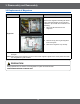
3. Disassembly and Reassembly MAGNETRON, MOTOR ASSEMBLY, VENT BLOWER AND HIGH VOLTAGE TRANSFORMER Oven must be removed from wall. REMOVING OVEN FROM WALL (2 PEOPLE REQUIRED) Oven is hooked on metal tabs at bottom of wall mounting plate and to cabinet by (3) top cabinet bolts. 3-1 Replacement of High Voltage Transformer Parts Explaination Photo Explaination 1. Disconnect oven power. Grille 2. Remove Grille. 1) Remove 2 screws 2) Slide the Grille to the left, then pull it straght out.
3. Disassembly and Reassembly 3-1 Replacement of High Voltage Transformer Parts Explaination Photo Explaination 4. Discharge the High voltage capacitor. 5. Disconnect all the leads. High voltage capacitor Base Bottom HV Trans 6. 7. 9 Take out the HV Trans. Remove Base bottom.
3. Disassembly and Reassembly 3-2 Replacement of Magnetron Parts Explaination Photo Explaination Remove the magnetron including the shield case, permanent magnet, choke coils and capacitors (all of which are contained in one assembly). 1. Disconnect all lead wires from the magnetron. Magnetron 2. 3. Remove nuts (4) securing the magnetron to the wave guide. Take out the magnetron very carefully.
3. Disassembly and Reassembly 3-3 Replacement of Door Assembly Parts Disassembly Photo Explaination Removal of Door Assembly Removal of Door C Removal of Key Door & Spring 11 1. Insert flat screwdriver into the gap between Door “A” and Door “C” to remove Door “C”. Be careful when handling Door “C” because it is fragile.Then remove the door assembly. 2. Insert flat screwdriver into the gap between Door “A” and Door “C” to remove Door “C”. • Becareful when handling Door “C” because it is fragile.
3. Disassembly and Reassembly 3-3 Replacement of Door Assembly Removal of Handle Removal of Door “E” PRECAUTION PERFORM MICROWAVE LEAKAGE TEST 12 4. Remove 2 screws, then handle is detached from Door “A”. 5. Following the procedure as shown in the figure, insert and bend a thin metal plate between Door “E” and Door “A” until you hear the ‘tick’ sound. • Insertion depth of the thin metal plate should be 0.5mm or less.
3. Disassembly and Reassembly 3-4 Replacement of Fuse Parts Explaination Photo Explaination The fuse is located on the noise filter. 1. Disconnect power and remove grille. 2. Replace the fuse. 3. When 20A fuse blows out by the operation of interlock monitor switch failure, replace the primary interlock switch, secondary interlock switch, door sensing switch, interlock monitor switch and power relay. 4.
3. Disassembly and Reassembly 3-6 Removal of stirrer Parts Explaination Photo Explaination The stirrer is motor driver and located on the upper side of the cavity. The oven uses a top feed wave guide. The stirrer is located in the wave guide and the motor is located on the wave guide. Stirrer 14 1. Disconnect power and open the door. 2. Remove the clip and turn the stirrer cover left. 3. Remove stirrer cover and the stirrer will come with it.
3. Disassembly and Reassembly 3-7 Replacement of Control Circuit Board Parts Explaination Photo Explaination Removal of Control Box Assembly 1. Disconnect power and remove grille. 2. Be sure to ground any static electric charge in your body and never touch the control circuit. 3. Remove a screw securing the control box assembly. 4. Disconnect the connectors from the control circuit board. 1.
3. Disassembly and Reassembly 3-8 Replacement of Cooktop lamp When replacing the night light, make sure that you are wearing gloves to avoid injury from the heat of the bulb. Parts Explaination Photo Explaination Cooktop Lamp 16 1. Unplug the oven or turn off the power at the main power. 2. Remove the bulb cover, and mounting screws. 3. Replace the bulb with a 40 watt appliance bulb. 4. Replace the bulb cover and mounting screws. 5. Turn the power back on at the main power supply.
3. Disassembly and Reassembly 3-9 Replacement of Oven Light Parts Explaination Photo Oven Light 17 Explaination 1. Remove the Grille 2. Remove the COVER LAMP by push the hook and put up the lever. 3. Replace the bulb with a 40 watt appliance bulb.
4. Troubleshooting 4-1 Parts checking method Parts Photo Good No Good Fuse 0.1 ~ 1 Ω 100 MΩ exceed T.C.O 0.1 ~ 1 Ω 100 MΩ exceed H.
4. Troubleshooting 4-2 Error Code Numbering Rule 1. 2. 3. 4. ERROR CODE NUMBERING RULE is applied to a microwave oven and an oven.(CMO, OTR, Grill, Convection, Commercial etc.) All sensors and devices have their own number. ex) Gas Sensor = 1, Temp. Sensor = 2, ... Of each device, No.1 and No.2 refer to “Open Error” (not sensed) and “Short Error”, respectively. This numbering rule has been applied to models to have been developed since January, 1, 2005. (But, GE or Customize model are excluded.
4. Troubleshooting Weight Sensor Error Code E-31 E-32 Gas Sensor Error Case (E-1X) Solution E-35 Open (When value of HEX is above “FF” for 5 seconds) Short In case the initial value of HEX is under “14” for 30 seconds while a weight sensor in operation. In case the initial value of K calculated by a weight sensor is above and under “±28” as value of HEX. In case the value of A is “-” as a weight sensor calculates. E-36 In case the door opens during sensor cooking.
4. Troubleshooting 4-4 Electrical Malfunction 4-4-1 E-11, E-21, E-27, E-29, E-2B, E-31, E-32, E-41, E-46, E-61 Sensor Open Error (E-11, E-21, E-27, E-29, E-2B, E-31, E-32, E-41, E-46, E-61) YES Connect the sensor. Is the sensor disconnected? NO Connect the wire properly. NO Is the sensor wire connected properly? : Check if the sensor housing is inserted into the connector of the main PCB.
4. Troubleshooting 4-4-2 E-12, E-22, E-28, E-32, E2A, E-2C ,E-42, E-2C, E-42 or E-62 Sensor Short Error (E-12, E-22, E-28, E-32, E2A, E-2C, E-42, or E-62) : Check if both terminals of the sensor are slightly shorted. Remove the shorted part of the temperature sensor. YES Is the sensor shorted? sensor NO Remove any foreign Substance from the shorted part.
4. Troubleshooting 4-4-3 E-13, E-14, E-43, E-44, E-63 Sensor Max Time Error (E-13, E-14, E-43, E-44, E-63) Insert food and heat it again. YES Does it heat up without placing food into it? : Since heating without placing food into the oven may damage the product, take care. NO Place food with moisture into it and heat it again. YES Does it heat with completely dried food? : Since heating completely dried food may burn the food, take care. NO Remove the an foreign substance or obstacle.
4. Troubleshooting 4-4-4 -SE- Key Short Error (- SE -) YES Is the key not recognized at all? NO YES Is the key recognized intermittently? NO Is a specific key not recognized? YES NO The membrane is defective. S/W Error Replace the Control Panel. NO After Power > On, does the symptom continue? YES Replace the PCB. Perform the operation again and check if it is working properly.
4. Troubleshooting 4-4-5 E-33, E-34 or E-35 Weight Sensor Error (E-33, E-34 or E-35) Has the turntable been placed over the roller properly? NO Place the turntable over the roller properly. Remove the foreign substance. YES YES Is the weight sensor contaminated by any foreign substance? NO Place the food in the center. YES Does the roller turn and press against the weight sensor? NO The sensor is out of order. Replace the sensor. Perform the operation again and check if it is working properly.
4. Troubleshooting 4-4-6 E-36 or E-47 Door Open Error(PH-Sensor, Weight Sensor), (E-36 or E-47) Close the door. YES Was the door open during the operation? NO Check the Door S/W and the housing. NO Is the door sensing part normal? YES S/W Error NO After Power > On, does the symptom continue? YES Replace the PCB. Perform the operation again and check if it is working properly. 26 : Check the housing connected to the door S/W and PCB and if it is opened or shorted intermittently.
4. Troubleshooting 4-4-7 E-45 Cooling Error (E-45) Remove any moisture of the sensor. : To remove moisture from the sensor, open the door for 5 minutes. YES Is the sensor wet? sensor NO Check the sensor terminal and housing. YES Is the sensor voltage over 3V? : Check if the GND and sensor terminal is maintained over 3V continuously during the initial cooking course using a multimeter. NO Replace the sensor.
4. Troubleshooting 4-4-8 E-51, E-53 or E-54 EEPROM Error (E-51, E-53, or E-54) Insert and solder an EEPROM NO EEPROM이 삽입been 되었는가? Has the EEPROM inserted? : An R4LCO40 or 24LCO4 EEPROM is to be used. Check if a proper EEPROM has been installed. YES Replace the EEPROM and repair the short circuit.
4. Troubleshooting 4-4-11 E-0b, E-2b, E-2C, 0t Cooling Fan Motor Sensor Error (E-0b, E-2b, E-2C, Ot) Is the temperature sensor of the PCB open? YES An “E-2b” error occurred. NO Insert the temperature sensor. Was there a shortcircuit in the temperature sensor of the PCB? YES An “E-2C, 0t” error occurred. NO Repair the short circuit. Is the temperature of the PCB over 90°C? YES An “E-0b” error occurred. NO NO Is the Cooling Motor rotating? S/W Error YES Check the Motor drive part.
4. Troubleshooting 4-4-12 E-23, E-26 Preheating Error (E-08, E-23, E-26) : Check the voltages of both heater terminals. Check the heater related drive part. NO Does the heater work? YES Replace the heater. YES Is the heater temperature very low? NO Reconnect the temperature sensor properly. NO Heater terminal : After operating the heater for more then 10 minutes check if the heater temperature remains low. Is the temperature sensor connected properly? YES Replace the heater.
4. Troubleshooting 4-4-13 E-02, E-03, E-04 or E-05 Cooling Time Over Selection Error (E-02, E-03, E-04, or E-05) Is this happening during the MW operation? YES NO Is it happening during the Grill operation? NO YES NO Over Time is set? Over Time is set? Is it happening during the Convection operation? YES An “E-02” error occurred. NO NO YES Over Time is set? Is it happening during the Combination operation? NO YES YES An “E-03” error occurred.
4. Troubleshooting 4-4-14 E-24 “E-09, E-24, E-0A” 가 표시된다 Oven Temperature Error An “E-09” error occurred. YES (E-24) Is the oven internal temperature maintained over 320 degrees? NO An “E-24, E-0A” error occurred. YES Has the oven internal temperature reached over 350 degrees? NO Reconnect the temperature sensor properly. NO Is the temperature NO sensor connectivity normal? YES Off TurnOven을 the oven off하고 and let it 충분히 cool sufficiently. 식힌다.
4. Troubleshooting 4-4-15 E-25 Initial Temperature Error (at MW mode), (E-25) Is the oven in MW mode? NO YES An “E-25” error occurred. Press the Cancel key. YES Is the internal temperature over 200 degrees? NO Press the Cancel key to cancel the current state. Connect it properly and try again. NO Is the sensor connectivity normal? YES S/W Error NO After Power > On, does the symptom continue? YES Replace the PCB. Perform the operation again and check if it is working properly.
4. Troubleshooting 4-4-16 E-06 Swing Heater Detection Error (E-06) Is the oven in Bake Toast mode? NO YES After waiting for 20 seconds, check if the micro-switch has been detected. NO Has the switch heater operated for 20 seconds? YES Has the micro-switch been detected? NO The micro-switch is defective Replace it. YES micro switch Is connectivity housing of the micro-switch normal? YES S/W Error NO After Power > On, does the symptom continue? YES Replace the PCB.
4. Troubleshooting 4-4-17 If oven malfunction *Inspection method Oven does not operate.
4. Troubleshooting 4-4-18 If button malfunction Buttons of the control panel do not work. Are button pressed in the correct order? NO Is the connector of the control panel normal? Refer to User Manual Tact type YES *Inspection method NO YES Replace PCB.
4. Troubleshooting 4-4-19 If food is not heated even though an oven works Food is not heated even though an oven works.
5.
5. Exploded Views and Parts List 5-2 Main Parts List (SNA : SERVICE NOT AVAILABLE) No. Code No. Description Specification Q’ty SA/ SNA Remark B001 3405-001034 SWITCH-MICRO 125/250VAC,16A,200GF,SPST-N 2 SA - B002 3405-001033 SWITCH-MICRO 125/250VAC 16A,200GF,SPSTNC 1 SA - B006 DE66-00168A LATCH-BODY MODULAR-2,PP,-,-,-,-,- 1 SA - B013 DE66-90106B LEVER-SWITCH LOWER PP,T1.4,-,-,2.
5. Exploded Views and Parts List 5-2 Main Parts List (Continued) (SNA : SERVICE NOT AVAILABLE) No. Code No. Description P032 DE92-90508A ASSY-HOLDER NUT P039 DE67-00232A P087 DE60-10111A P088 P089 Specification Q’ty SA/ SNA Remark OTR6,-,-,-,-,- 2 SA DUCT-UPPER MODULAR3,PP,T1.
5. Exploded Views and Parts List 5-3 Door Parts List D006 D005 D004 D011 D007 D024 D002 D020 D049 (SNA : SERVICE NOT AVAILABLE) No. Code No. Description Specification Q’ty SA/SNA Remark D002 DE64-01949F DOOR-A SMH9151S,PC,-,-,-,-,SILVER,NO 1 SNA D004 DE94-01469G ASSY DOOR-E MAYTAG1.5/1.6,-,COATING 1 SA ASSY DOOR - D005 DE01-00091A FILM-DOOR -,POLYESTER,-,L458,T0.
5. Exploded Views and Parts List 5-4 Control Parts List C082 C003 C001 P157 C005 C009 C004 (SNA : SERVICE NOT AVAILABLE) No. C001 Code No. DE94-01806K Description ASSY CONTROL PANEL Specification SMH9151S,SILVER,PC,1.
5. Exploded Views and Parts List 5-5 Standard Parts List (S.N.A : SERVICE NOT AVAILABLE) Level Code No.
6. PCB Diagrams 6-1 PCB Diagrams (This Document can not be used without Samsung’s authorization) ⑬ ⑦ ⑥ ⑧ ⑤ ① ⑨ ② ④ ⑩ ③ Function and Rule ⑪ Part Name ⑫ Main Relay Inrush Relay Power High Relay Power Low Relay Bright Relay Vent High Relay Vent Low Relay Vent Mid Relay Night Relay Inrush Connector Power & Relay Connector Parts No.
6.
7.
7.
8. Schematic Diagrams 8-1 Schematic Diagrams (This Document can not be used without Samsung’s authorization) LIVE R101 51K PC101 PC817 1N4007 1N4007 D101 D102 1N4007 1N4007 D103 D104 INTERRUPT +5V R16 R02 4.7K OR01 2K TR14 KRC246M 4.7K PTC1 390M ZNR1 10D471 +5V R01 10K 4 3 INT L101 1mH 2K 2 1 5 R105 510K IC101 LNK564P C103 1nF D105 1N4007 BP S8 D S1 S7 FB S2 7 8 4 3 C104 POWER SUPPLY SOURCE C101 C102 4.7uF 4.
GSPN (Global Service Partner Network) Contry Web Site North America service.samsungportal.com Latin America latin.samsungportal.com CIS cis.samsungportal.com Europe europe.samsungportal.com China china.samsungportal.com Asia asia.samsungportal.com Mideast & Africa mea.samsungportal.com © Samsung Electronics Co., Ltd. January. 2009 Printed in Korea Code No.