SyncMaster NC220P LED Monitor User Manual The color and the appearance may differ depending on the product, and the specifications are subject to change without prior notice to improve the performance.
Table Of Contents MAJOR SAFETY PRECAUTIONS Before You Start . . . . . . . . . . . . . . . . . . . . . . . . . . . . . . . . . . . . . . . . . . . 1-1 Care and Maintenance . . . . . . . . . . . . . . . . . . . . . . . . . . . . . . . . . . . . . . 1-2 Cleaning the Monitor . . . . . . . . . . . . . . . . . . . . . . . . . . . . . . . . . . . . . . . 1-3 Safety Precautions . . . . . . . . . . . . . . . . . . . . . . . . . . . . . . . . . . . . . . . . . 1-4 INSTALLING THE PRODUCT Package Contents . . . . . .
Correct Disposal of This Product (Waste Electrical & Electronic Equipment) . . . . . . . . . . . . . . . . . .
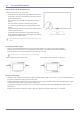
1 Major Safety Precautions 1-1 Before You Start Icons used in this manual ICON NAME MEANING Caution Indicates cases where the function may not work or the setting may be canceled. Note Indicates a hint or tip to operate a function. Using this Manual • Make yourself fully aware of the safety precautions before using this product. • If a problem occurs, refer to the 'Troubleshooting' section.
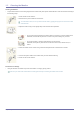
1-2 Care and Maintenance External Surface and Screen Maintenance Clean the product with a soft, damp cloth. • Do not clean the product with an inflammable substance such as benzene or thinner or with a wet cloth. This may result in a problem with the product. • Do not scratch the screen with your fingernails or a sharp object. This may result in scratches or damage to the product. • Do not clean the product directly by spraying water onto the product.
1-3 Cleaning the Monitor Cleaning the Monitor • The panel and exterior of the cutting-edge monitor scratch easily and require careful attention. Clean the monitor according to the following steps. 1. Power off the monitor and PC. 2. Disconnect the power cable from the monitor. To avoid electric shock, be sure you disconnect the cable by gripping the plug and do not touch the cable with wet hands. 3. Wipe the monitor using a soft, slightly damp cloth that has been squeezed .
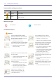
1-4 Safety Precautions Icons used for safety precautions ICON NAME MEANING Warning Failing to follow the precautions marked with this sign, may result in a serious injury or even a fatality. Caution Failing to follow the precautions marked with this sign, may result in a personal injury or property damage. Meaning of Signs Do not perform. Must be followed.
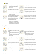
Caution Do not let the product drop while moving it. • This may result in a problem with the product or injury. When installing the product on a console or shelf, make sure that the front of the product does not protrude out of the console or shelf. • Otherwise, this may cause the product to fall off and result in a malfunction or injury. • Make sure to use a cabinet or shelf suitable to the size of the product.
Avoid moving the product by pulling the power cord or antenna cable. • Otherwise, it may result in electric shock, fire or a problem with the product due to damage to the cable. When a gas leak occurs, do not touch the product or the power plug and ventilate immediately. • A spark may result in an explosion or fire. Avoid lifting up or move the product by holding only the power cord or signal cable. Avoid using or placing inflammable spray or objects near the product.
Do not let water enter the DC power device or get the device wet. Avoid turning the product upside down or move the product holding only the stand. • An electric shock or fire may result. • • Avoid using the product outdoors where it can be exposed to rain or snow. • Be careful not to get the DC power adapter wet when you wash the floor. This may cause the product to fall resulting in damage to the product or injury. Do not put the DC power adapter near to any heating apparatus.
2 Installing the Product 2-1 Package Contents • Unpack the product and check if all of the following contents have been included. • Store the packaging box in case you need to move the product at a later stage. • If any items are missing, contact your dealer. • Contact a local dealer to purchase optional items.
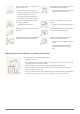
2-2 Installing the Stand Place a soft cloth over the table to protect the product and place the product onto the cloth so that the front of the product is facing downwards. Turn the stand in the direction indicated by the arrow. Insert the stand base into the stand in the direction of the arrow. Do not remove the fixing pin until you are finished attaching the stand. Tightly fasten the screw to the bottom of the base. After installing the stand, place the product upright.
2-3 Adjusting the Product Tilt and Height The color and shape of parts may differ from what is shown. Specifications are subject to change without notice to improve quality. • To adjust the height, remove the fixing pin. • The monitor tilt and height can be adjusted. • Hold the top center of the product and adjust the height carefully.
2-4 Rotating the Monitor Screen You can rotate your monitor as shown below. • Be sure to fully extend the stand before rotating the monitor. • If you rotate the monitor without fully extending the stand, the corner of the monitor may hit the floor and get damaged. • Do not rotate the monitor counterclockwise. The monitor may get damaged.
2-5 Installing a Wall-mount Kit or Desktop Stand Before Installation Place a protective cloth or cushion on a flat surface. Next, place the product with the face down on top of the cloth or cushion. Unfasten the screw from the back of the product. Lift and detach the stand.
2-6 Connecting to your Network The connecting part may differ depending on the product model. • It is not supported when the network speed is below or equal to 10Mbps. • Use Cat5(*STP Type) cable for the connection. *Shielded Twist Pair Attach the DC-DC converter (UPoE PD) to the back of the product. - Push the adapter until you hear a “click.” Connect the LAN cable (connected to the PSE device) to the [LAN] port on the right side of the UPoE PD adapter.
• • Ferrite Core for LAN cable : The ferrite cores are used to shield the cables from interference. When connecting the ferrite core to a cable, open the ferrite core and clip it around the cable near the plug as shown in the figure. : One ferrite core should be no more than 2 inches from the end of the LAN cable that is inserted into the product.
2-7 Connecting to another Monitor The connecting part may differ depending on the product model. • Connect between the [DVI OUT] port on the product and the DVI port on your monitor using a DVI cable. You can connect more monitors via [DVI OUT]. (For presentation purposes).
2-8 • 2-8 Connecting a SERIAL Cable Devices which support RS-232C connection (interface) can be connected.
2-9 Connecting with a PC The connecting part may differ depending on the product model. • Connect the [RGB IN] port of the product to the D-Sub port of your PC with a D-Sub cable. Use the [RGB IN] port to directly connect the monitor to a PC.
2-10 Connecting a Stereo Cable The connecting part may differ depending on the product model. • 2-10 Connect the [AUDIO IN] port on the rear side of the monitor to the sound card of the PC.
2-11 Connecting Headphones The connecting part may differ depending on the product model. • Connect your headphones to the Headphone connection terminal. You may connect your headphones to the monitor.
2-12 Connecting MIC The connecting part may differ depending on the product model. • Connect the microphone cable to the MIC port on the monitor. You may connect your microphone to the monitor.
2-13 Kensington Lock An anti-theft lock allows you to use the product securely even in public places. The locking device shape and locking method depend on the manufacturer. Refer to the user guide provided with your anti-theft locking device for details. The lock device is sold separately. To lock an anti-theft locking device: 1. Fix the cable of your anti-theft locking device to a heavy object such as a desk. 2. Put one end of the cable through the loop on the other end. 3.
3 Using the product 3-1 What is a PC over IP? • This monitor can decode and display the screen of the server PC encoded and transmitted through the network (LAN) as well as display the computer screen like a conventional monitor. This monitor shows a far more improved performance than a normal RDP and has been designed to support a resolution of 1920*1080 pixels for high-quality graphic work.
3-2 Connect to the host PC using a LAN cable Host PC Hub LAN Cable Monitor Connect the UPoE PD adapter on the back of the monitor to the PSE device using the LAN cable. Connect the mouse and the keyboard to the USB ports. Connect the LAN port on the back of the monitor and the hub. Connect the hub and the LAN port of the host PC. The host PC must have an IP address. After connecting the LAN and setting the IP address, you can view the host PC screen on the monitor.
3-2-1 Connecting USB • The connecting part may differ depending on the product model. • The port supports up to USB 2.0. VMware View 4.6 or later is required. Data transfer rate may decrease depending on the network conditions. • Connect USB devices such as a mouse, keyboard and external storage devices (DSC (Digital Still Camera), MP3, external storage, etc.).
3-3 Plug & Play If you turn the power on after purchasing the product, a message regarding the optimal resolution setting appears on the screen. Select a language and the optimal resolution. ▲/▼ : You can select a language with these buttons. MENU : If you press this button, the message disappears. • The message appears up to 3 times if the resolution has not been set to the optimal resolution. • To set the resolution to the optimal resolution.
3-4 Standard Signal Mode Table The monitor has one optimal resolution for the best visual quality depending on the screen size due to the inherent characteristics of the panel, unlike for a CDT monitor. Therefore, the visual quality will be degraded if the optimal resolution is not set for the panel size. It is recommended setting the resolution to the optimal resolution of the product. If the signal from the PC is one of the following standard signal modes, the screen is set automatically.
3-5 Installing the Device Driver If you install the device driver, you can set up the appropriate resolution and frequency for the product. The device driver is included on the CD-ROM supplied with the product. If the supplied drive file is corrupted, please visit the Samsung Electronics website(http://www.samsung.com/), and download the driver. 1. Insert the driver installation CD-ROM into the CD-ROM drive. 2. Click on "Windows Driver". 3.
3-6 Installing a USB-to-Serial Driver Install the driver on the server PC. 1. Insert the driver installation CD-ROM into the CD-ROM drive. 2. Click on "USB-SERIAL Driver". 3. Click Next. 4. Click Finish.
3-7 Product Operating Buttons Product Operating Buttons Icon Description Press this button to view the On Screen Display (OSD). This button is also used to exit the OSD or to return to a higher-level OSD menu * Key Lock This function locks the buttons on the front of the product to prevent the current settings from being changed by others. MENU Lock: Press and hold the MENU button for 5 seconds. The key lock mode will be enabled.
Icon Description If the 11th digit of the model code is M, the model has internal speakers. Speaker E.g.) LF22NEBHBNMMN • Press one of the buttons on the monitor. OSD Guide will appear on the screen. • If you press a button on the front of the monitor, an OSD Guide will display showing the function of the button before the menu for the pressed button appears. • To go to the menu, press the button on the front of the monitor again. • OSD Guide may vary according to functions and models.
3-8 Using the Screen Adjustment Menu (OSD: On Screen Display) The Screen Adjustment Menu (OSD: On Screen Display) Structure Top Menus PICTURE Sub Menus Brightness Contrast Sharpness Red Green Blue Bright Coarse Fine Color COLOR Color Tone Gamma SIZE & POSITION H-Position V-Position Menu H-Position Menu V-Position SETUP&RESET Reset Language Display Time Menu Transparency INFORMATION - Monitor functions may vary according to models. Please refer to actual product.
Menu Description Provides preset picture settings optimized for various user environments such as editing a document, surfing the Internet, playing games, watching sports or movies and so on. • If the preset picture modes are not sufficient, you can configure the and directly using this mode. • This mode provides the picture setting appropriate for surfing the Internet (text + picture).
Menu Description Expresses natural colors more clearly without changing the picture quality by using proprietary digital picture quality improvement technology developed by Samsung Electronics. Color • - Turns the < Color> function off. • - You can compare the pictures processed by < Color> with the original pictures. • - Provides a clearer picture including areas corresponding to skin color.
Menu Description Moves the position of the display area on the screen horizontally. H-Position This function is only available in mode. Moves the position of the display area on the screen vertically. V-Position This function is only available in mode. Menu H-Position You can adjust the horizontal position of the OSD. Menu V-Position You can adjust the vertical position of the OSD.
INFORMATION Menu Description Shows the frequency and resolution set on the PC. INFORMATION Using the product For models with an Analog interface only, is not shown in the .
4 Installing the Software 4-1 PCoIP On Screen Display (OSD) The On Screen Display (OSD) local GUI is displayed to the user when the device is powered on and a PCoIP session is not in progress. The OSD provides a mechanism to connect to a host device via the Connect Screen. The Connect Screen is presented to the user on startup. The Connect Screen also allows access to the Options Window. The Options Window is accessible through the button on the Connect Screen.
Connect Button Selecting the Connect button initiates a PCoIP or RDP session, depending on the session settings. While the PCoIP connection is pending, the OSD local GUI will display a “Connection Pending” message. When the connection is established, the OSD local GUI will disappear and be replaced with the session image. Figure 2-2: OSD Connect Screen (Connecting) OSD Menu Selecting the menu will produce a list of selections.
Figure 2-3: OSD Menu Window The window allows the administrator to access window tabs with settings that define how the Portal operates and interacts with its environment.
Figure 2-4: Configuration • When is enabled, the device will contact a DHCP server to be assigned an IP address, subnet mask, gateway IP address and DNS servers. When disabled, the device requires these parameters to be set manually. • The IP Address field is the device’s . If DHCP is disabled, this field is required. If DHCP is enabled, this field is not editable.
The Portal Label parameters can also be configured using the Webpage Administration Interface. Figure 2-5:
Figure 2-6: Configuration • If the option is enabled, the device can be configured and controlled by an external connection manager. • The selector allows the administrator to choose whether the connection manager is identified by or by Fully Qualified Domain Name (FQDN).
Figure 2-7: Configuration • If the option is enabled, the device will dynamically discover peer devices using SLP Discovery, without requiring prior knowledge of their locations in the network. This can dramatically reduce configuration and maintenance effort for complex systems. SLP discovery requires routers configured to allow multicast, and therefore DNS-SRV Discovery is the recommended discovery mechanism.
Table 2-2 shows the peer identity parameters available when either method is chosen. If an invalid IP address or DNS name is entered, the OSD will prompt the administrator to correct it.
The button resets all configuration and permissions to factory default values. Tab The tab allows configuration for use with a VMware View Connection Server. The VMware View parameters can also be configured using the Webpage Administration Interface.
The parameter allows the administrator to specify the port used to communicate to the VMware View Connection Server. The parameter allows the administrator to specify the to communicate with the VMware View Connection Server. The parameter allows the administrator to specify that the Portal automatically always connects with the VMware View Connection Server at startup.
Selecting the button clears all of the displayed event log messages. Tab The tab allows the administrator to view PCoIP-specific statistics for the last PCoIP session that was active on the Portal. can also be viewed using the Webpage Administration Interface.
Figure 2-13: • The field reports the total number of PCoIP packets sent from the Portal to the Host in the last active session. • The ield reports the total number of PCoIP packets received from the Host to the Portal in the last active session.
Figure 2-14: Tab The tab allows the administrator to ping a device to see if it is reachable across an IP network. This may be useful for determining if a Host is reachable.
Window The window allows an administrator to access the Version tab containing information about the device. The Version information can also be viewed using the Webpage Administration Interface. Figure 2-16: VPD Information Vital Product Data (VPD) is information provisioned by the factory to uniquely identify each Portal or Host.
Revision code of the current PCoIP bootloader • Build date of the current PCoIP bootloader Window The window allows the user to access window tabs that define the mouse and keyboard settings and the PCoIP image quality. The tabs in the User Settings menu are: • • • Tab The tab allows a user to change the mouse cursor speed settings for the OSD and RDP sessions.
Figure 2-18: • The field allows a user to configure the Portal keyboard repeat delay. • The field allows a user to configure the Portal keyboard repeat rate. • The field allows a user to test the chosen keyboard settings. The allows a user to change the image settings on the PCoIP system.
Window The window allows an administrator to update the administrative password for the device. Note that this will affect the web interface and the local GUI. • Care must be taken when updating the Portal Password as the Portal may become unusable if the password is lost. • The Password can also be updated using the Webpage Administration Interface. • Some PCoIP devices have password protection disabled by default and this window is not available.
4-2 Natural Color What is Natural Color? One of the problems with using a PC is that the colors you see on the screen are different from the colors of printed pictures or source images input through a scanner or digital camera. Natural Color is a color management system developed by Samsung Electronics to resolve this problem. This software works with Samsung products only and enables you to adjust the displayed colors on the screen to match the colors of the printed pictures.
4-3 MultiScreen What is MultiScreen ? MultiScreen enables users to use the monitor by partitioning multiple sections. Installing the Software 1. Insert the installation CD into the CD-ROM drive. 2. Select the MultiScreen setup program. If the pop-up screen for the software installation does not appear on the main screen, find and double-click the MultiScreen setup file on the CD-ROM. 3. When the Installation Wizard appears, click [Next]. 4.
5 Troubleshooting 5-1 Monitor Self-Diagnosis • You can check if the product is working properly using the Self-Diagnosis function. • If a blank screen is displayed and the Power LED blinks even if the product and the PC are properly connected, perform the self-diagnosis function according to the procedures below. 1. Turn the product and the PC off. 2. Separate the signal cable from the product . 3. Turn the product on. 4. If the product is working properly, the message appears.
5-2 Before Requesting Service Please check the following before requesting After-Sales service. If the problem continues, please contact your nearest Samsung Electronics Service Center. A BLANK SCREEN APPEARS / I CANNOT TURN THE PRODUCT ON. Is the product properly connected to the PSE device? The product operates only when connected to a device that supports a CISCO 60W PoE. Is the message displayed on the screen? Check the cable connecting the PC and the product.
THE COLOR IS DISPLAYED IN 16 BIT (16 COLORS). THE COLOR HAS BEEN CHANGED AFTER CHANGING THE GRAPHICS CARD. Did you install the device driver for the product? Windows XP : Set the color again by selecting Control Panel → Appearance and Themes → Display → Settings. Windows ME/2000 : Set the color again by selecting Control Panel → Display → Settings. Windows Vista : Change the color settings by selecting Control Panel → Appearance and Personalization → Personalization → Display settings.
5-3 FAQ FAQ! How can I change the frequency of the video signal? PLEASE TRY THE FOLLOWING! You have to change the frequency of the graphics card. Windows XP : Change the frequency by selecting Control Panel → Appearance and Themes → Display → Settings → Advanced → Monitor, and then change the refresh rate under Monitor Settings. Windows ME/2000 : Change the frequency by selecting Control Panel → Display → Settings → Advanced → Monitor, and then change the refresh rate under Monitor Settings.
6 More Information 6-1 Specifications MODEL NAME Panel NC220P Size 22 inches (55cm) Display area 473.76 mm (H) × 296.1 mm (V) 18.7 inches (H) × 11.7 inches (V) Synchronization Horizontal 31~70kHz Vertical 56~75Hz Display Color Resolution 16.7M Optimum resolution 1680 X 1050 @ 60Hz Maximum resolution 1680 X 1050 @ 60Hz RGB Analog Input Signal, Terminated 0.7 Vp-p ± 5 % Separate H/V sync, Composite TTL Level (V high ≥ 2.0 V, V low ≤ 0.8 V) Maximum Pixel Clock 146.
6-2 Power Consumption Power Indicator Power Consumption (Typical) 6-2 NORMAL OPERATION POWER OFF (POWER BUTTON OFF) POWER OFF (MECHANICAL SWITCH OFF) On Off Off 38 W less than 4 W 0W • The actual power consumption may be different from the indicated power consumption above if the system conditions or settings are changed. • To stop any power consumption, turn off the switch or disconnect the power cable on the back.
6-3 Contact SAMSUNG WORLDWIDE If you have any questions or comments relating to Samsung products, please contact the SAMSUNG customer care center. NORTH AMERICA U.S.A 1-800-SAMSUNG (726-7864) http://www.samsung.com CANADA 1-800-SAMSUNG (726-7864) http://www.samsung.com/ca http://www.samsung.com/ca_fr (French) MEXICO 01-800-SAMSUNG (726-7864) http://www.samsung.com LATIN AMERICA ARGENTINA 0800-333-3733 http://www.samsung.com BRAZIL 0800-124-421 http://www.samsung.
EUROPE CZECH 800 - SAMSUNG (800-726786) http://www.samsung.com Samsung Electronics Czech and Slovak, s.r.o., Oasis Florenc, Sokolovská 394/17, 180 00, Praha 8 DENMARK 70 70 19 70 http://www.samsung.com FINLAND 030 - 6227 515 http://www.samsung.com FRANCE 01 48 63 00 00 http://www.samsung.com GERMANY 01805 - SAMSUNG (726-7864,€ 0,14/Min) http://www.samsung.com CYPRUS From landline : 8009 4000 http://www.samsung.com GREECE From landline : 80111- SAMSUNG (7267864) http://www.samsung.
CIS RUSSIA 8-800-555-55-55 http://www.samsung.com GEORGIA 8-800-555-555 http://www.samsung.com ARMENIA 0-800-05-555 http://www.samsung.com AZERBAIJAN 088-55-55-555 http://www.samsung.com KAZAKHSTAN 8-10-800-500-55-500 (GSM: 7799) http://www.samsung.com UZBEKISTAN 8-10-800-500-55-500 http://www.samsung.com KYRGYZSTAN 00-800-500-55-500 http://www.samsung.com TADJIKISTAN 8-10-800-500-55-500 http://www.samsung.com MONGOLIA UKRAINE http://www.samsung.com 0-800-502-000 http://www.
MIDDLE EAST IRAN 021-8255 http://www.samsung.com OMAN 800-SAMSUNG (726-7864) http://www.samsung.com KUWAIT 183-2255 http://www.samsung.com BAHRAIN 8000-4726 http://www.samsung.com EGYPT 08000-726786 http://www.samsung.com JORDAN 800-22273 http://www.samsung.com MOROCCO 080 100 2255 http://www.samsung.com SAUDI ARABIA 9200-21230 http://www.samsung.com U.A.E 800-SAMSUNG (726-7864) http://www.samsung.com AFRICA CAMEROON 7095- 0077 http://www.samsung.
6-4 Correct Disposal of This Product (Waste Electrical & Electronic Equipment) (Applicable in the European Union and other European countries with separate collection systems) This marking on the product, accessories or literature indicates that the product and its electronic accessories (e.g. charger, headset, USB cable) should not be disposed of with other household waste at the end of their working life.