4 CHANNEL DVR User Manual SDS-P3040
4 Channel DVR User Manual Copyright ©2012 Samsung Techwin Co., Ltd. All rights reserved. Trademark is the registered logo of Samsung Techwin Co., Ltd. The name of this product is the registered trademark of Samsung Techwin Co., Ltd. Other trademarks mentioned in this manual are the registered trademark of their respective company. Restriction Samsung Techwin Co., Ltd shall reserve the copyright of this document.
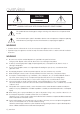
overview Important Safety Instructions Read these operating instructions carefully before using the unit. Follow all the safety instructions listed below. Keep these operating instructions handy for future reference. Read these instructions. 3) Heed all warnings. 2) 4) 5) 6) 7) 8) 9) ! overview 1) Keep these instructions. Follow all instructions. Do not use this apparatus near water. Clean only with dry cloth.
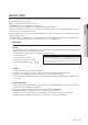
overview CAUTION RISK OF ELECTRIC SHOCK. DO NOT OPEN CAUTION : TO REDUCE THE RISK OF ELECTRIC SHOCK, DO NOT REMOVE COVER (OR BACK) NO USER SERVICEABLE PARTS INSIDE. REFER SERVICING TO QUALIFIED SERVICE PERSONNEL. This symbol indicates that dangerous voltage consisting a risk of electric shock is present within this unit. This exclamation point symbol is intended to alert the user to the presence of important operating and maintenance (servicing) instructions in the literature accompanying the appliance.
Before Start Warning Battery It is essential that when changing the battery in the unit, the replacement battery must be of the same type otherwise there may be a possibility of an explosion. The following are the specifications of the battery you are using now. • Normal voltage : 3V CALIFORNIA USA ONLY • Normal capacity : 170mAh This Perchlorate warning applies only to primary CR (Manganese Dioxide) Lithium coin cells in the product sold or distributed ONLY in California USA.
overview Operating Temperature The guaranteed operating temperature range of this product is 0°C ~ 40°C (32°F ~ 104°F). This product may not work properly if you run right after a long period of storage at a temperature below the guaranteed one. Prior to using a device that has been stored for a long period in low temperatures, allow the product to stand at room temperature for a period. Especially for the built-in HDD in the product, its guaranteed temperature range is 5°C ~ 55°C (41°F ~ 131°F).
Contents 3 5 7 9 11 12 13 Important Safety Instructions Before Start Contents Features Part Names and Functions (Front) Part Names and Functions (Rear) Remote Control connecting with other device 15 15 16 16 17 19 19 Installation Checking the installation environment Connecting the Video, Audio and Monitor Connecting the USB Connecting the Camera (SDC-5340BC) Connecting the RS-485 Device Connecting the Network live 21 23 28 30 30 30 31 Getting Started Live Screen Configuration Live Mode Zoom Audio On
overview search & play 75 web viewer 80 backup viewer 107 appendix 110 8_ overview 75 78 Search Playback 80 81 82 83 84 90 94 104 105 Introducing Web Viewer Connecting Web Viewer (Mac) Using Live Viewer (Mac) Connecting Web Viewer (Windows) Using Live Viewer (Windows) Using Search Viewer Viewer Setup About Mobile Viewer 107 SEC Backup Viewer 110 111 113 116 119 Product Specification (Camera) Product Specification (DVR) Default Setting Troubleshooting Open Source License Report on the Product
Features yy Supports CIF(S)/2CIF(M)/4CIF(L) recording formats yy With the network specific codec, network transfer enabled regardless of the recording conditions yy De-interlacing processor for better picture quality yy Display of HDD information and status by using HDD SMART yy Hard Disk overwrite function yy Mass storage hard disk backup through high-speed USB 2.
overview package Contents Please unwrap the product, and place the product on a flat place or in the place to be installed. Please check the following contents are included in addition to the main unit.
pArT nAmeS And funCTionS (fronT) DIGITAL VIDEO RECORDER ! overview POWER REC a bc Part Names a b c USB Port 1 Functions 2 Remote Control Receiver 3 LED Indicator 4 Connects the USB devices. AUDIO IN Input the remote control signal. NETWORK DC 12V 1 ALARM IN 2 3 4 G POWER : Displays the power ON/OFF status. VIDEO OUT AUDIO OUT ALARM OUT 1 COM G VGA CONSOLE USB REC : Lights on when recording is in progress.
DIGITAL VIDEO RECORDER overview POWER REC pArT nAmeS And funCTionS (reAr) Sdr-3100 a 1 b c d AUDIO IN 2 DC 12V ALARM IN 2 3 4 G ALARM OUT 1 COM G 4 VIDEO OUT AUDIO OUT j CONSOLE USB VGA i Part Names h g Functions a b c CAMERA IN AUDIO IN Audio input signal port (RCA jack, CH1). d Ground e f g h i j NETWORK ` Add a separate earth-grounding cable to use your product safely.
MM `` [CONSOLE] is designed for the service repair purpose only. `` If using the VGA cable, the source from VGA will be displayed as main image on the screen along with the OSD menus. Then, the BNC port will output the video signal alone. `` If not using the VGA cable, the source from BNC will be displayed as main image on the screen along with the OSD Remote Control SEARCH BACKUP Displays the search menu. Displays the Backup Menu. MODE Changes the screen mode. DVR Activates the DVR function.
overview Using the Numeric buttons 1. Press any button among 1 to 4. 2. Move to the selected channel number. Changing the Remote Control ID 1. Press the ID button of the remote control and check the ID displayed on the DVR screen. The factory default ID of the remote control is 00. 2. Enter 2 digits of your selection in order, while pressing the system [ID] button. 3. When ID input is done, press the system [ID] button again to check the setting.
connecting with other device Installation Please take note of the followings before using this product. Checking the installation environment Samsung Digital Video Recorder (“DVR” hereinafter) is a stateof-art security device, and contains mass storage hard disk(s) and critical circuits inside. Temperature Unit: ºC One Year: 24HR X 365 DAY =8,760 HR When the temperature rises inside the product, the product may breakdown and the product life be shortened.
connecting with other device ConneCTinG The video, Audio And moniTor M ` Only one mouse port is available. AUDI O IN VIDEO OUT AUDI ALA 1 2 RM IN 3 4 O OU T VGA ALA G 1 RM OUT COM G + - RS 48 5 NETW ORK DC 12 V CONS OLE USB ConneCTinG The uSB 1. By factory default, a USB port is provided for external connection. 2. You can connect a USB HDD, USB memory or mouse to the USB port. 3.
ConneCTinG The CAmerA (SdC-5340BC) a b c d e Name a b c d e Description Camera Fitting Groove Groove that is used to fit the camera bracket. There are two grooves; one on the top and one on the bottom. Lens Focal length of 3.6mm enables you to cover relatively longer range of monitoring. IR LED Illumination Sensor DVR Connection Cable These infrared LED's are controlled by the illumination sensor. Detects incoming light to control the IR LED.
connecting with other device Connecting with dvr AUDIO VIDEO OUT AUDIO IN OUT ALA 1 2 RM IN 3 4 VGA ALA G 1 RM OUT COM G + - RS 485 NETW ORK DC 12 CONS V OLE USB installing the camera The camera can be installed on the wall, ceiling, shelf or a desired position using the provided bracket. 1. Select a position where you want to install the camera. ` Make sure the selected position can sustain the weight of the camera. 2. Attach the camera bracket to the wall using the supplied screws.
ConneCTinG The rS-485 deviCe Connect the rear [RS-485 +, –] port to the PTZ camera or system keyboard. ` You can connect and control the PTZ camera which supports the RS-485 communication. + RS-485 ` Check if the RS-485 device is compatible with the product first. ` Pay attention not to change the polarity (+/-) of the RS-485 device when connecting it. ` Depending on camera’s type, connection polarity can be different. For further information, refer to the respective PTZ Camera’s documentation.
connecting with other device Connecting to the Network using the router AUDI O IN VIDEO OUT AUDI ALA 1 2 RM IN 3 4 O OU T VGA ALA G 1 RM OUT COM G + - xDSL or Cable Modem RS 48 5 NETW ORK DC 12 CONS V OLE USB Broadband Router NETWORK xDSL or Cable Modem External Remote PC DDNS Server (Data Center) Connecting to Network through ADSL AUDI O IN VIDEO NETWORK OUT AUDI ALA 1 2 RM IN 3 4 O OU T VGA + - RS 48 RJ-45 Ethernet Cable (Direct Cable) Phone(A DSL) Lin e Hub/Switche
live GeTTinG STArTed Starting the system M ! Live 1. Connect the power cable of the DVR to the wall outlet. ` It takes about 10 seconds to display the start screen after booting. 2. You will see the initialization screen. The initialization process will last about 1 minute. If a new HDD is installed, the initialization process may take longer. 3. The live screen appears with a beep.
live Login To access a DVR or restricted menu, you should have logged in to the DVR. 1. In live mode, right-click any area of the screen. You will see the context sensitive menu as in the right figure. 2012-01-01 01:10:25 Scene Mode Audio Off Freeze Stop Alarm Record Play Search Backup Main Menu Shutdown Hide Launcher Login 2. Click . The login dialog appears. You can also see the login dialog to access a desired menu by pressing the [menu] button on the remote control.
Live Screen Configuration Icons on the Live Screen You can check the status or operation of the DVR with the icons on the live screen. ! live 2012-01-01 00:00:01 CAM 01 Part Names a b Current Date, Time Login Information Description Displays the current time and date. When you are logged in, the “LOG ON” icon will be displayed. Displayed if the zoom function is activated. Freezes the screen temporarily.
live Part Names f Description Camera Name/ Channel Displays the camera name and the changed channel, if any. Displays the resolution of the recording screen. (Page 53) Displayed in PTZ setting, and highlighted yellow if PTZ is in operation. g Displays AUDIO ON/MUTE. Camera Operation Not displayed in video mode if deactivated. Displayed if a motion detected in the condition that the motion detection is set to . Displays the current record mode from Record/Event/Schedule.
Split mode menu The context sensitive menu in split mode differs, depending on the login/logout status. Audio Off Freeze Stop Alarm Record Play Search Backup Main Menu Shutdown Hide Launcher Logout Menu a b c d e f g h i j k l b 2012-01-01 01:10:25 Scene Mode ! Live l k j i h g f e d c a Scene Mode Refer to “Live Mode”. (Page 28) Freeze Refer to “Freeze”. (Page 30) Audio On/Off Stop Alarm Record/Stop Description Refer to “Audio On/Off ”.
live Single mode menu The single mode menu is available only in Single Mode. The context sensitive menu for the One Channel mode, in Split mode is different from that of the Single mode. 2012-01-01 01:10:25 a b Full Screen PTZ Control Zoom In Audio On Freeze Stop Alarm Record Play Shutdown Hide Launcher Logout Menu Description a Full Screen Select and click a desired channel in Split mode to switch to the full screen of the selected channel. b Zoom In Enlarges the selected image.
view the Launcher menu The Launcher menu appears on the bottom of the live screen. 1. In Live mode, right-click to display the context menu and select . 2012-01-01 01:10:25 ! Live 2. Move the cursor to the bottom and click a desired item in the Launcher menu. M ` If no input is entered for 10 seconds, the menu will disappear. ` The Launcher menu can be accessed only by using the mouse.
live Live Mode Displays 4 live video images in 3 different modes. Switching the screen mode To switch the split mode, select a screen mode in the launcher menu, or right-click to select a screen mode in the context menu. Press the [MODE] button on the remote control to switch the mode in the sequence of the launcher menu items.
Channel Setting You can display the channel in a desired area of a split screen. 1. Click a camera name to display a channel list where you can select a different channel. CH1 CH2 CH3 CH4 ; CH1 CH4 CH2 CH3 CH1 CH1 CH3 CH2 CH2 CH1 Switching to Single Mode CH1 CH2 When in split mode, select and double-click a desired channel to switch to its Single mode. CH4 CH2 CH2 Press the number corresponding to aCH1desired channel the remote control to switch to its Single mode.
live Zoom This is available only in Single Live mode. In Single mode, select a desired area and use the Zoom function to enlarge it twice. 1. Select in the right-click menu. Press the [Zoom] button on the remote control, or simply click < box appears. > in the launcher menu. The zoom 2. Use the direction keys, or drag and drop to specify an area to enlarge. 3. Press the [enTer] button, or double-click the selected area to enlarge it twice.
Event Monitoring This will display the channel in sync with a specific event (Motion/Video Loss) if it occurs. In “Monitor > Event Display”, set the event monitoring to ON/OFF and specify the event display time. (Page 49) • If the second event occurs within the set time of , the first event will last until the second one is terminated. (Page 49) `` Ex : If you set to 5 seconds, and only one event occurs in CH 1.
main menu You can setup the system properties, devices, and options for recording, event, backup and network. SYSTem SeTuP You can setup Date/Time/Language, Permission, System Properties and Log. Date/Time/Language You can check and setup the current Date/Time and time related properties, as well as the language used for the interface on the screen. Setting the Date/Time/Language Set the Date/Time/Language Using the mouse may help make setup easier. 1. Press the [menu] button on the remote control.
Date/Time/Language Date/Time/Language Holiday Date 2012-01-01 YYYY-MM-DD Time 08:14:24 24 Hours Time Zone GMT+09:00 Time Sync. DST Language Setup Dec First (Sun) 0 Dec First (Sun) 0 English OK Cancel • Time Sync. : You can set the DVR’s current time > regularly if you select to use
main menu Setting Holiday You can set specific dates to Holidays according to your preferences. Holidays are applied to and too. Using the mouse may help make setup easier. 1. Use the up/down buttons ($%) in window to select , and press the [enTeR] button. 2. Select . A calendar for Holiday setup appears. > buttons to select year or month, 3. Use the left/right < and press the [enTeR] button.
Permission management You can set permissions of each user over the DVR's specific function and settings. ! main menu Setting the administrator You can set and change Administrator’s ID and password. The administrator can use and set all menu items and functions. Using the mouse may help make setup easier. 1. Use the up/down buttons ($%) in window to move to , and press [enTeR] button. 2. Select . A dialog for Admin ID and Password input appears.
main menu Setting the Group You can create user groups and setup permissions for those user groups. You can register a user for each group in . Using the mouse may help make setup easier. 1. Use the up/down buttons ($%) in window to move to , and press [enTeR] button. 2. Select . A window for , , , and setup appears.
To restrict the user permissions If the admin restricts all permissions of an added group, the users belonging to that group can access only the default minimum menus and can change the user’s own password only. 2. Log in with a registered user ID. ! main menu 1. Start the DVR. If all permissions are restricted, only the Login dialog should appear. Login ID abc Password OK 3. Right-click any area on the screen. If all permissions are restricted, only the accessible context menus should appear.
main menu Setting the user Users can be added only if a group was created in menu. Using the mouse may help make setup easier. 1. Use the up/down buttons ($%) in window to move to , and press [enTeR] button. 2. Select . A window for Add User appears. 3. Use direction buttons ($%_ +) to select from the window. A window for “add user” appears. You can configure the Network Viewer settings including name, ID, viewer, Select Group and password.
Setting Permissions You can set restricted access for all general users. Items with restrictions will require logging in for use. Using the mouse may help make setup easier. 2. Select . The Restricted Access, Restriction on Network Access, Auto Log out, Manual Input of ID setup screen appear. 3. Use direction buttons ($%_ +) to move to a desired item, and set the value. • Restricted Access : All menu items allowed for a user can be set with restricted access.
main menu System management You can check the system version, update to a newer version, as well as data backup and initialization. Checking the System information You can check the current system version, broadcasting system, MAC address. You can update the system. Using the mouse may help make setup easier. 1. Use the up/down buttons ($%) in window to move to , and press [enTeR] button. 2. Check the Software Version, Broadcast Format and MAC Address.
5. Press in the “System upgrade” window. ` While updating, it shows the progress. • Updating progresses with 3 steps as shown in the figure. System Management System Information Settings System Information Software Version v1.0xh_yymmddhhmmss Format BroadcastS/W NTSC Upgrade MAC Address 00:00:F0:54:FF:FF Software upgrading... Device USB2FlashStorage Version V1.
main menu Settings You can copy and import the DVR settings by using a storage media. Using the mouse may help make setup easier. 1. Use the up/down buttons ($%) in window to move to , and press [enTeR] buttBon. 2. Select . A window of storage device and load factory default appears.
event Log Event log shows recorded events on alarms, motion detections and video loss. It also shows the log and its timestamp. Using the mouse may help make setup easier. 2. Select . 3. Use direction buttons ($%_ +) to move to the desired item. 4. Set Search Day, Channel and Type and the press . ` Refer to “Using the Calendar”. (Page 34) Click on the calendar < > to display the calendar window.
main menu SeTTinG THe DeViCe You can setup Camera, Storage Device, Remote Device and Monitor. Camera Setting the Camera You can set Video, Audio, Channel Name and Dwell Time of a Camera. Using the mouse may help make setup easier. 1. Press Bthe [menu] button on the remote control. 2. Use the left/right button (_ +) to select . Device setting menu is selected. Logout 3. Use the up/down buttons ($%) to move to , and press [enTeR] button.
• Privacy Region : You can specify a certain area of the camera video to be protected for your privacy. Screen Setup CH1 50 50 6. When the camera setup is done, press . Init 50 OK Apply to All CH Cancel To set the privacy region Select . When “Privacy Region” window appears, select a channel for detection and set the area of motion detection. • To set the area in “Privacy Region” window In the “Privacy Region” window, select desired region from < >.
main menu Setting the PTZ To use Camera’s PTZ functions, ID and protocols of each camera and DVR should be matched. For other settings, refer to the “Remote Devices” settings. (Page 48) Using the mouse may help make setup easier. 1. Use the up/down buttons ($%) in window to move to , and press [enTeR] button. 2. Select . A window of PTZ settings appears. Camera PTZ Camera CH ID 1 0 > None 2 1 > Protocol None 3 2 > None 4 3 > None 3.
Formatting You can format a storage device. Using the mouse may help make setup easier. 2. Select . A window for selection of device for formatting appears. Storage Device Format Device Device HDD Alarm Select HDD 1 Used/Total Used 12.28G/499.37G Internal Manage 3. Use direction buttons ($%_ +) to select a device to be formatted. Formatting deletes all recordings. Proceed formatting? OK Cancel Format OK 4. Select on the bottom of the screen.
main menu HDD alarm You can set alarm settings for HDD defects such as Check Alarm Output Port, Replace Alarm Output Port, and its duration. Using the mouse may help make setup easier. 1. Use the up/down buttons ($%) in window to move to , and press [enTeR] button. 2. Select . A window for setting HDD check and replace output ports and their durations appears. 3. Use direction buttons ($%_ +) to move to the desired item.
monitor You can select which item(s) to be displayed on the screen. Using the mouse may help make setup easier. 1. Use the up/down buttons ($%) in window to move to , and press [enTeR] button. 2. Select . 3. Use direction buttons ($%_ +) to move to a desired item, and set the value. • Event Display : Sets the dwell time of the event channel display on the monitor when an event occurs.
main menu Setting the Screen mode You can configure the Live screen and Split Screens. Using the mouse may help make setup easier. 1. Use the up/down buttons ($%) in window to move to , and press [enTeR] button. 2. Select . 3. Use direction buttons ($%_ +) to move to a desired item, and set the value. • Live Screen : Select split modes for the Live screen. 4-split screens are included by default. • Play Screen : Select split modes for the playback screen.
SeTTinG THe ReCORDinG You can setup scheduled recording, event recording and other recording related settings. Make your reservation on a date and time to schedule the recording on specified time. Using the mouse may help make setup easier. 1. Press the [menu] button on the remote control. 2. Use the left/right button (_ +) to select . Record menu is selected. Logout 3. Use the up/down buttons ($%) to move to , and press [enTeR] button.
main menu Recording Color Tags Color Function White No Recording Blue Event Orange Green Continuous Both(Cont&Evnt) Description No schedule / event recording Scheduled recording only Event recording only Both scheduled / event recordings Each press of a selected cell will cycle through --. event Record Duration You can set the beginning and ending point of a recording on an event. Using the mouse may help make setup easier. 1.
ReC Quality / Resolution You can set resolution, fps and quality of recordings by channel, and by recording type of standard / event. ! main menu Setting Standard Recording Properties You can set each channel’s resolution, quality and fps for normal recordings. Using the mouse may help make setup easier. 1. Use the up/down buttons ($%) in window to move to , and press [enTeR] button. 2. Select . 3. When the recording setup is done, press .
main menu Record Option You can set the recording to stop or overwrite when the HDD is full. Using the mouse may help make setup easier. 1. Use the up/down buttons ($%) in window to move to , and press [enTeR] button. Record Option 2. Use direction buttons ($%_ +) to move to a desired Auto Delete item, and set the value. • Disk End Mode : If selected , recording will continue despite the HDD full while overwriting the oldest.
SeTTinG THe eVenT You can set recording options for motion, and video loss event. You can set target detection region and motion, as well as the alarm signal output. When the motion detection region is set, it detects motion within the area. Using the mouse may help make setup easier. 1. Use the up/down buttons ($%) in window to move to , and press [enTeR] button. A window of motion detection area setup appears. 2.
main menu Video Loss Detection You can set the alarm to be generated on a camera disconnection, which causes a video loss. Using the mouse may help make setup easier. 1. Use the up/down buttons ($%) in window to move to
BaCKuP You can check the backup device and set the backup schedule by channel or by time. The product only supports external HDD of USB memory and USB type. (Page 111) You can backup the desired data to a connected device. Using the mouse may help make setup easier. 1. Press the [menu] button on the remote control. Logout 2. Use the left/right button (_ +) to select . Backup menu is selected. Return Backup Backup 3. Press the [enTeR] button. A backup window appears.
main menu 5. When the backup setup is done, press . ` If no available device is recognized for backup, button is not activated. J ` The application may slow down during the backup. ` You can switch to the menu screen during the backup in operation, but playback of data is not available. ` If backup has failed, select “Device > Storage Device” and check the free space of the HDD and check also if the HDD is properly connected.
• IP, Gateway, Subnet Mask, and DNS - For : You can directly input IP address, Gateway, Subnet Mask and DNS. - For : IP address, Gateway, and Subnet Mask are set automatically. • User ID, Password : In case you selected ADSL, provide the “user iD” and its “Password”. M Protocol Connection Mode ADSL Bandwidth 600kbps IP 192.168. 1.200 Gateway 192.168. 1. Subnet Mask 255.255.255.
main menu notification J ` In a multi-browser environment, the web port should be set to 80 (private port). Select one between 4505 and 4530 for RTSP • network Overview Router (External IP: 109.112.92.133, Local IP: 192.168.1.1 Cable/ADSL Modem Internet DIGITAL VIDEO RECORDER POWER REC Local PC System DVR 1 WEB DIGITAL VIDEO RECORDER POWER DVR 1 DDNS Server (www.samsungipolis.com) REC DVR 2 RTSP DVR 2 WEB RTSP IP 192.168.1.200 192.168.1.200 192.168.1.202 192.168.1.
• 1st Set Port Forwarding Setting Port Forwarding is 4520~4524 (4520, 4521, 4522, 4523, 4524) Port Forwarding is 80 SDR-3100 TCP TCP 4520 80 192. 168. 1. 200 4520 ! main menu SDR-3100 192. 168. 1. 200 80 • 2nd Set Port Forwarding Setting Port Forwarding is 4525~4529 (4525, 4526, 4527, 4528, 4529) Port Forwarding is 81 SDR-3100 SDR-3100 TCP TCP 4525 81 192. 168. 1. 202 4525 192. 168. 1.
main menu Connecting and Setting the network Networking may differ from the connection method, check your environment before setting the connection mode. When no router is used • Static iP mode - Internet connection : Static IP ADSL, leased line, and LAN environments allows connection between the DVR and remote user. - DVR Network Settings : Set the in menu of the connected DVR to . ` Consult your network manager for IP, Gateway and Subnet Mask.
When a router is used JJ `` To avoid IP address conflict with the DVR's static IP, check followings : -- Internet connection : You can connect the DVR to a router which is connected to an ADSL/Cable modem or a router in a Local Area Network (LAN) environment. • Setting the DVR Network 1. Set the in menu of the connected DVR to . 2. Check whether the set IP address is in the static IP range provided by the Broadband Router.
main menu • Setting Router’s Port Forwarding 1. Set the protocol to . Connection Mode 2. External Port Range : Enter the TCP Port set in the in menu of the connected DVR. If more than one DVRs are connected to the router, the TCP port can be different. Connection Protocol Type Port(TCP) TCP 4520 Port(UDP) 3. Internal PC IP Address : Enter the IP address set to the in menu of the connected DVR. ~ Unicast Multicast IP 224.126.63.
Click for updating your router IP address. b ! main menu Type your router Username & Password. If you haven’t changed them, skip this procedure, for it provides default value. c 4. Click <(4)Do it now> in Check List for choosing the ports. b Click for updating your router IP address. IP Address : 192.168.1.200 Type : TCP Start Port : 80 End Port : 80 IP Address : 192.168.1.
main menu 5. After checking if the list is right, click <(5)Do it now> for updating your router. DDnS You can set the DDNS site for a remote user’s network connection. Using the mouse may help make setup easier. 1. Use the up/down buttons ($%) in window to move to , and press [enTeR] button. 2. Use virtual keyboard to enter user inputs. ` Refer to “Using Virtual Keyboard”. (Page 35) • If selected or , input fields are deactivated.
DDnS Setting • Setting DDnS in the DVR Set in the menu of the connected DVR to the following : Ex) Protocol Type : TCP Port (TCP) : 4520~4524 DDNS Site : iPOLiS ❖ iPOLiS DDnS Setting 1. Visit http://www.samsungipolis.com or http://www.samsungipolis.co.kr and click . 2. If you have ID & PASSWORD, insert them. Otherwise, click for a new account. 3. After log in, register your set with your information.
main menu 4. After registration, you can see the list as below. 5. Select and fill Server Name out with your registration information. DDNS DDNS Site iPOLiS Server Name www.samsungip... Product ID SDR3100HOME Quick Connect DDNS Host Address Not Use Use http://www.samsungipolis.com/SDR3100HOME OK Cancel OK Cancel 6. You can see changed to in 10 minutes, if all the network settings are right.
mailing Service You can send an e-mail to a DVR-registered user at a specific time interval, or if an event occurs. ` If an event occurs with a channel where the camera’s video is set to or the remaining recording count is set to , only the text notification will be sent to the applicable email address. ! main menu M ` The e-mail receivers are not able to adjust the attached image quality. SmTP Setting Sets the SMTP mail server. Using the mouse may help make setup easier. 1.
main menu event Setting You can set the interval and type of the event that will be sent to the user. Using the mouse may help make setup easier. 1. In the setting window, press the up/down ($%) button to move to and press the [enTeR] button. 2. Select . 3. Use direction buttons ($%_ +) to move to a desired item and set the value. • Event Interval : Set the event interval.
Recipient Setting You can add/remove a recipient(s) to/from the specified group and edit the group if necessary. Using the mouse may help make setup easier. 2. Select . Mailing Service SMTP Group Event Recipient Group All Group Group Add Name e-Mail Address Del 3. Use direction buttons ($%_ +) to move to a desired item and set the value. Previous/ Next Page OK • Add : You can select a recipient name, e-mail address or group.
search & play COnTROLLinG a PTZ DeViCe The DVR enables you to adjust the settings of a PTZ camera as well as an ordinary one to your preference. PTZ Device The PTZ device can be activated only if a channel in connection with the PTZ camera is selected. Getting started with PTZ The PTZ camera is available, only if a channel is selected, in the following way : ` Using the remote control buttons Press the [PTZ] button on the remote control.
using the PTZ camera You can use one camera to perform all functions of PAN, TILT and ZOOM for monitoring multiple places and set the preset to your preference in a desired mode. M 2012-01-01 01:10:25 ` Be sure to configure PTZ working environments before operation, since the PTZ Working(Active) mark can be appeared to be activated even when PTZ is not operative. PTZ Control CAM01 Auto Pan Select Scan Select Camera Setup Select Preset 2.
search & play Preset Setting A preset is a set of specific target points of a PTZ camera, and up to 127 presets per a camera can be stored. 1. In PTZ Control mode, use the direction buttons to adjust the camera in a desired direction. 2. Select the key. The virtual keyboard for inputting the preset will appear. ` Refer to “Using Virtual Keyboard”. (Page 35) • • • • Save : You can save the preset settings. Rename : You can change the settings of the existing presets.
search & play SeaRCH You can perform the search for recorded data by the time or by the search criteria such as an event. You can access the menu directly in Live mode. 1. In Live mode, right-click any area of the screen. The Live menu appears. ! SeaRCH & PLaY 2012-01-01 01:10:25 Scene Mode Audio Off 2. Select . Or, press the [SeaRCH] button on the remote control. Freeze Stop Alarm Record Play Search Backup Main Menu Shutdown Hide Launcher Logout 3. The Search menu appears.
search & play • Zoom In : The map enlarges in detail. It will switch in the sequence of 24 hours - 16 hours - 8 hours - 4 hours. • Zoom Out : The map will switch in the reverse order of the detailed mode above. It will switch in the sequence of 4 hours - 8 hours - 16 hours - 24 hours. M ` Double-click a desired time to zoom it in/out.
Backup Search Using the mouse may help make setup easier. 1. Select in the menu. 2. Use direction buttons ($%_ +) to set the search criteria and press the [enTeR] button. • Record Period : Displays the record period. • Channel info : Displays the recorded channel. • Play Start Time : Select a time that you start playing. 3. Select a data item and click . The screen switches to the backup data playback mode. Backup Search USB:USB2FlashStorage No.
search & play PLaYBaCK Play You can play data stored in the HDD and backup a desired portion of the data. Using the mouse may help make setup easier. 1. In Live mode, click in the right-click menu or > in the launcher menu, or press the Play button on < the remote control. 2012-01-01 01:10:25 Scene Mode Audio Off Freeze 2. Use the up/down button ($%) to select a menu. ` For data search, refer to .
using the Playback Button ! SeaRCH & PLaY ReC b c Part Names m Play Timeline Indicates the current playback point, and can be used to move. b Skip Backward Moves backward by unit time. Backward Fast Play Backward Slow Play Functions c n Used for quick backward playback. Used for backward frame-by-frame search while in PAUSE. Step Backward Moves backward by one frame at a time. Pause Stops playing the current video temporarily.
web viewer Introducing Web Viewer What is Web Viewer? Web Viewer allows remote access to your DVRs. You have access to live video, archived video etc. Product Features • Remote access from a standard browser • Supports 1, 4 camera viewing formats (maximum of 4 cameras in the list). • Gets JPEG, BMP format images to print and save to “Print or Save JPEG, BMP format images”. • Record video in AVI format-compatible with popular media players. (needed the H.
connectIng Web VIeWer (MAc) ❖ Safari on MAc. 1. Click [click now to Install] to display the installation screen as shown. 2. Double-click the [Silverlight.pkg] icon to display the Silverlight plug-in installation screen as shown. 3. Click [continue] to start installing Silverlight plug-in. When done, you will see the screen as below. 4. Click [close] to exit from the Silverlight plug-in installation screen.
web viewer • If Microsoft Silverlight plug-in is already installed 1. Use a web browser to connect to the DVR. 2. If Silverlight plug-in is already installed, you will see the screen as shown. 3. If this is the case, perform Step 3 [tcP port & Web Viewer port settings] below. 4. If the screen above does not appear, check if the DVR set is connected properly with a valid IP address.
connectIng Web VIeWer (WIndoWS) 1. Open your web browser and type the IP address or URL of DVR into the URL address box. http://www.samsungipolis.com/HOMEDVR 2. Set the Admin ID and password same to those of the DVR Admin. For general users, enter the DVR user ID and password. J ` The default password can be exposed to a hacking thread so it is recommended to change the password after installing the product. ` Set password for your wireless network if you use the product with a wireless router.
web viewer 5. You may have “Windows Security Alert” that attempts to block this with the Windows Firewall. In that case, click to start Web Viewer. 6. Installation is complete. Now you can see the main screen of Live Viewer. uSIng lIVe VIeWer (WIndoWS) The Live Viewer screen consists of following : b a c d e f g h i k j a This displays the IP address and the model name of the connected DVR. b These menus consist of , , , .
oSd Information display a The channel number, video size, and IP address of the connected DVR are displayed. b ! Web VIeWer b This icon will appear if the audio signal is currently being output. a c The current date and time will be displayed according to the selected time information display setting or . d Motion icon appears when motion is detected. It disappears when pressed the [AlArM] button of the DVR.. e It displays whether the PTZ controls are active.
web viewer connected dVr This displays the IP address and the status of the connecting DVR. M ` Connection failure message No Response : Appears when the DVR does not respond. Access Denied : Appears when the maximum number of users is exceeded. ` The number of simultaneous connections are limited to 4. Setting the display of the oSd time Information Select or for the OSD time information display setting.
• PrInt : Prints out the selected screen out of the currently displayed live screens. It also prints the IP address, time, camera number and the current event status together. ! Web VIeWer • record : Saves the current image on the screen and saves it as a avi video file. M ` To record it, it is required at least 1GB of available space. ` The default saving path is “C:\Program Files\Samsung\DVR Web Viewer\VideoClip\Live”.
web viewer using PtZ camera Click the direction buttons to control the camera. •< > •< > •< > You can zoom in or out an image by using the ZOOM button. You can adjust the entering light amount by using the IRIS button. You can adjust the focus by using the FOCUS button. • Menu : Appears the camera menu screen.
• Preset : Moves the lens direction to a preset direction. 1. If you click a preset, the camera moves to the selected preset's position. 2. You can delete the selected preset or all presets. ! Web Viewer 3. You can save a new preset number and name. MM `` You can save presets up to 127. • Auto Pan : Moves the camera lens direction between 2 points set for the camera. • Scan : Moves the camera lens direction between 2 preset points of the camera.
web viewer uSIng SeArch VIeWer The Search Viewer screen consists of following : b a c d e f g k h i j a This displays the IP address and the model name of the connected DVR. b There are 4 tabs available: , , , . c Switch to a split mode. d Shows the IP address and model name of the connected DVR. e Select the format of OSD information that will be displayed on Live Viewer. f These buttons are used for capture, print, and save the image.
Split-Screen You can change the split mode by clicking each number icon. ! Web VIeWer SINGLE MODE QUAD MODE > button. • Click < The screen displays the selected camera connected to the DVR in “SIngle Mode”. • Click < > button. The screen displays the selected camera connected to the DVR in “QuAd Mode”. connected dVr This displays the IP address and the status of the connecting DVR. M ` Connection failure message No Response : Appears when the DVR does not respond.
web viewer Saving the live Screen on the Pc • cAPture : Saves the current screen into a BMP or JPEG file. M ` The default saving path is “C:\Program Files\Samsung\DVR Web Viewer\SnapShot\Search”. To change the saving path, )> button and then select the path click
Searching the recorded Video in the calendar ! Web VIeWer If the video data has been recorded on a date, the date is distinguished in green. If you click the date, the recorded video information is displayed in the time line. When you click , it will be synchronized with the system time (date) of the current PC. check duplicates If there are found duplicates in the same timeline after you changed the DVR time, those duplicates will be listed in the <0> order with the latest one on top.
web viewer controlling Playback a b e f c g h d i a Fast backward : Reverse-plays faster(2x~64x). b reverse Play : Performs Reverse Play. c Play : Performs playback. d Fast Forward : Plays faster(2x~64x). e go to First : Moves the beginning time of recorded video in the time line. f Step backward : Performs one step reverseplay by one frame. g Pause : Stops the playback temporarily. h Step Forward : Performs one step forward by one frame.
• time Synchronization Setup Set the time synchronization. ! Web VIeWer • display Date Format : Set the date type. Time : Select a time format to display on the screen. • dSt (daylight Saving time) DST is displayed an hour ahead of the standard time of the time zone. • language Select a preferred language for the DVR. holiday You can set specific dates to Holidays according to your preferences. For more information, refer to in the menu.
web viewer • group Users are classified into groups and the permission can be set according to the group. ` First of all, add a group. • user You can add, change or remove a user or users. • Setup You can set the user permission. System Management For more information, refer to in the menu. (Page 39) • System Information You can see information of the current system. Check the software version, broadcast format and MAC address.
device camera • camera You can configure the settings of the camera that is connected to the DVR. • Privacy region You can specify a certain area of the camera video to be protected for your privacy. • PtZ You can configure the settings of the PTZ camera that is connected to the DVR. Set the ID and protocol. English _97 ! Web VIeWer You can check a list of devices that are connected to the DVR and configure the necessary settings. Click in the menu screen.
web viewer Storage device You can check and change the settings of the storage device. • device You will see a list of storage devices that are connected to the DVR. You can check the type, used/total, usage and status of the device. • hdd Alarm You can set the alarm output channel and the alarm duration for an error. remote device Specify the use of remote control and the remote control ID so that you can synchronize with the DVR.
• Mode You can switch between live mode and play mode. ! Web VIeWer record For more information, refer to . (Page 51) recording Schedule If you set a recording schedule for a specific date and time, the recording will start at that specific time. - Apply to All CH : Click to display the confirmation window. event record duration You can set the start and end times of recording that will be activated if an event occurs.
web viewer rec Quality & resolution • Standard/event You can set the resolution, frame rate and recording quality for each channel. record option You can set the Disk End Mode. event For more information, refer to . (Page 55) Motion detection You can set the motion detection mode and the sensitivity as well as the alarm output type and the duration.
• Motion region Set the target motion detection area ! Web VIeWer Video loss detection You can set the alarm output time if a video loss occurs. Alarm Schedule You can schedule the alarm output according to the day of the week and the time. The default setting is Event Sync, which activates the alarm only if an event occurs.
web viewer network For more information, refer to . (Page 58) connection A remote user can access the DVR via the network to check the current mode and the IP address. • connection You can set the network connection route. • Protocol You can configure the protocol related settings. ddnS You can check the DDNS settings. ` If you select , the “DDNS Host Address” item will be displayed.
live transfer A remote user can set the images of the DVR. • live transfer ! Web VIeWer A remote user can set the image resolution of the transferred data. Mailing Service You can specify the SMTP server that sends a mail if an event occurs and set the recipient group and users. • SMtP You can set the server that sends mails and specify if you use the authentication process. • event You can set the event interval and specify which events the server sends mails for.
web viewer • group You can add a group to receive the mail if an event occurs and set the permission to receive the event mail for each group. • recipient You can add a user or users who will receive the mail. About Click . Displays the model name of connected DVR and the version of Web Viewer SDR-3100 20XX. XX.
Mobile Viewer What is Mobile Viewer? Using a Smartphone 1. Download the Samsung iPOLiS mobile app. On an Android phone, visit Play Store. On an iPhone, visit App Store. 2. Search for Samsung iPOLiS. 3. Launch the iPolis mobile app add the DVR. On an Android phone, tap on the menu icon and tap . On an IPhone, at the Add Device pop-up tap .
backup viewer 4. Register the DVR to the iPOLiS mobile. JJ Name : Create a name for the DVR you are adding Model : Select the DVR model Host : If you are using Samsung iPolis DDNS, enter the host DDNS Host Address you wrote down earlier. It should be www.samsungipolis.com/Product ID HTTP Port : If you are using iPolis DDNS, you do not need to enter this information RTSP Port : Enter the Port (TCP) you wrote down earlier. Camera : Select the cameras you want to view. 5.
backup viewer Sec bAcKuP VIeWer You can play a file that is backed up in the format of SEC. Backup in the format of SEC will involve in generating two files: one for the backup data and one for the viewer. ! bAcKuP VIeWer If you run the backup file viewer, the backup data file will be automatically played. recommended System requirements PCs with a lower specification than the recommended below may not fully support forward/backward and high-speed playback.
backup viewer Name a b c f / Audio A toggle button. Each time you press this button, the audio output will toggle between activated and deactivated. You can adjust the volume level from 0 to 100. Saves the current screen as an image file. Supported file formats include BMP and JPEG. Screen Printout File Tamper Detection Prints out the current screen. You should have installed the appropriate printer driver before you can print out the screen.
Name Description Displays the next frame. This is available only if the playback is stopped. Play A toggle button. Press it once to start playing the video and switch the button mode to 'Pause', and press it again to switch the button mode to Play and stop playing temporarily. Displays the previous frame. This is available only if the playback is stopped.
appendix Product Specification (Camera) ❖❖ SDC-5340BC Item Electrical Input Voltage Power Consumption Video SDC-5340BCN 3W 1/3'' CMOS Scanning System Interlace Synchronization Frequency Horizontal Resolution Min. Illumination S/N Ratio (Y Signal) Lens Focus Length Max.Aperture Ratio Angular Field of View Operational 720 x 480 Internal H: 15,734 Hz, V: 59.94 Hz 600TVL OLux (IR-LED) 46dB 3.
Product Specification(DVR) `` Design and specifications are subject to change without prior notice. ❖❖ SDR-3100 Video Live Performance Operating System 4 composite video 0.5-1 Vpp, 75 ohm Frame rate 30fps NTSC, 25fps PAL Resolution Multi Screen display Embedded Compression Record Rate Recording Mode Overwrite modes Pre-Alarm Post-Alarm Search & Playback Search mode Smartphone Storage 704x480 NTSC, 704x576 PAL 704x480 NTSC, 704x576 PAL 1, 4, PIP Linux H.
appendix Details Item Security Interface Monitors Password Protection 1 Admin, 10 Group, 10 User per 1 Group VGA Analog RGB 1024x768 resolution(BNC or VGA selected in booting.
Default Setting This returns the factory default settings.
appendix Category Details Monitor Device Monitor Mode Recording Schedule Event Record Duration Event Video Loss Detection Alarm Schedule 114_ appendix Video Output VGA Display All Display Position Setup 30 Live Mode ALL Play Mode ALL PRE Event OFF POST Event 1 min Event Motion Detection OFF Both(Cont&Evnt) REC Quality/Resolution Record Option Event Display CH1 Normal Recording Recording Factory Default Disk End Mode Resolution CIF(S) Frame Rate NTSC: 7 fps, PAL: 5 fps Reco
Category Details Connection Mode Protocol Network DDNS Live Transfer Static IP Bandwidth 2Mbps IP 192.168.1.200 Gateway 192.168.1.1 Subnet Mask 255.255.255.0 DNS 168.126.63.
appendix Troubleshooting Symptom Countermeasures The system does not turn on and the indicator on the front panel does not work at all. yy Check if the power supply system is properly connected. yy Check the system for the input voltage from the power source. yy If the problem persists even after you have taken the above actions, check the power supplier and replace it with a new one if neccessary. Some channels display just a black screen even if they receive video sources.
Symptom Countermeasures yy This message is displayed if there occurs a problem with the time setting of the internal clock or an error in the clock itself. Contact the retailer or the service center for more information. The time bar is not displayed in Search mode. yy The timeline can switch between normal and extension mode. In extension mode, the time bar may not be displayed in the current timeline. Switch to normal mode or use the left or right button to navigate through the time bar.
appendix Symptom Countermeasures Recording does not work. yy If your player does not display a Live image at all, that indicates recording does not work so first check if you see an image on the screen. yy Recording does not work if the recording settings are not properly configured. 1) Manual Record: Press the [REC] button on the remote control to start recording. 2) Scheduled Record: Specify a desired time in Menu – Record Recording Schedule. Recording will start at the specified time.
Open Source License Report on the Product The software included in this product contains copyrighted software that is licensed under the GPL/LGPL. You may obtain the complete Corresponding Source code from us for a period of three years after our last shipment of this product by sending email to help.cctv@samsung.com If you want to obtain the complete Corresponding Source code in the physical medium such as CD-ROM, the cost of physically performing source distribution might be charged.
normally distributed (in either source or binary form) with the major components (compiler, kernel, and so on) of the operating system on which the executable runs, unless that component itself accompanies the executable.
Preamble The GNU General Public License is a free, copyleft license for software and other kinds of works. The licenses for most software and other practical works are designed to take away your freedom to share and change the works. By contrast, the GNU General Public License is intended to guarantee your freedom to share and change all versions of a program--to make sure it remains free software for all its users.
5. Conveying Modified Source Versions. You may convey a work based on the Program, or the modifications to produce it from the Program, in the form of source code under the terms of section 4, provided that you also meet all of these conditions: a) The work must carry prominent notices stating that you modified it, and giving a relevant date. b) T he work must carry prominent notices stating that it is released under this License and any conditions added under section 7.
8. Termination. You may not propagate or modify a covered work except as expressly provided under this License. Any attempt otherwise to propagate or modify it is void, and will automatically terminate your rights under this License (including any patent licenses granted under the third paragraph of section 11).
16. Limitation of Liability.
d) I f a facility in the modified Library refers to a function or a table of data to be supplied by an application program that uses the facility, other than as an argument passed when the facility is invoked, then you must make a good faith effort to ensure that, in the event an application does not supply such function or table, the facility still operates, and performs whatever part of its purpose remains meaningful.
so as to satisfy simultaneously your obligations under this License and any other pertinent obligations, then as a consequence you may not distribute the Library at all. For example, if a patent license would not permit royalty free redistribution of the Library by all those who receive copies directly or indirectly through you, then the only way you could satisfy both it and this License would be to refrain entirely from distribution of the Library.
(online or textual) provided with the package.Redistribution and use in source and binary forms, with or without modification, are permitted provided that the following conditions are met: 1. Redistributions of source code must retain the copyright notice, this list of conditions and the following disclaimer. 2.
Correct Disposal of This Product (Waste Electrical & Electronic Equipment) (Applicable in the European Union and other European countries with separate collection systems) This marking on the product, accessories or literature indicates that the product and its electronic accessories (e.g. charger, headset, USB cable) should not be disposed of with other household waste at the end of their working life.
SALES NETWORK SAMSUNG TECHWIN CO., LTD. Samsungtechwin R&D Center, 701, Sampyeong-dong, Bundang-gu, Seongnam-si, Gyeonggi-do, Korea, 463-400 TEL : +82-70-7147-8740~60 FAX : +82-31-8018-3745 SAMSUNG TECHWIN AMERICA Inc. 100 Challenger Rd. Suite 700 Ridgefield Park, NJ 07660 Toll Free : +1-877-213-1222 Direct : +1-201-325-6920 Fax : +1-201-373-0124 www.samsungsv.com www.samsungtechwin.com www.samsungsecurity.com www.samsungipolis.com SAMSUNG TECHWIN EUROPE LTD.