SyncMaster 400TSn-2/460TSn-2 LCD Monitor User Manual
Safety Instructions Notational Note These safety instructions must be followed to ensure your safety and prevent property damage. Make sure to read the instructions carefully and use the product in the correct manner. Warning / Caution Failure to follow directions noted by this symbol could result in bodily harm or damage to the equipment.
Safety Instructions Ensure that the power plug is plugged into the power outlet firmly and correctly. • Otherwise, this may result in fire. Do not forcefully bend or pull the power plug and do not place any heavy material on it. • Otherwise, this may result in fire. Do not connect multiple appliances to the same power outlet. • Otherwise, this may cause fire due to overheating. Do not disconnect the power cord while using the product.
Safety Instructions Keep heating appliances as far away from the power cord or the product as possible. • Otherwise, this may result in electric shock or fire. Do not install it in a badly ventilated location such as a bookcase or closet. • Otherwise, this may result in fire due to an increase in the internal temperature. When putting the product down, make sure to put it down softly. • Otherwise, this may result in damage to the screen display. Do not place the front of the product on the floor.
Safety Instructions When cleaning the power plug pins or dusting the power outlet, clean it with a dry cloth. • Otherwise, it may result in fire. When cleaning the product, make sure to disconnect the power cord. • Otherwise, it may result in electric shock or fire. When cleaning the product, disconnect the power cord and clean it softly with a dry cloth. • (Do not use chemicals such as wax, benzene, alcohol, thinner, mosquito repellant, lubricant, or cleaner.
Safety Instructions If thunder or lightening is occurring, do not touch the power cord or antenna cable. • Otherwise, this may result in electric shock or fire. Do not try to move the monitor by pulling only the wire or the signal cable. • Otherwise, it may fall and result in electric shock, damage to the product or fire due to damage to the cable. Do not lift or move the product back and forwards or right and left while only holding the power cord or signal cables.
Safety Instructions If you continually move closer to the product screen, your eyesight may be failing. Take a rest for at least five (5) minutes after using the monitor for one (1) hour. This reduces the weariness of your eyes. Do not install it in an unstable location such as an unstable rack or uneven surface or a location exposed to vibrations. • Otherwise, it may fall and cause personal injury and/or damage the product.
Safety Instructions The batteries (and rechargeable batteries) are not ordinary refuse and must be returned for recycling purposes. The customer is responsible for returning the used or rechargeable batteries for recycling. • The customer can return used or rechargeable batteries to a nearby public recycling center or to a store selling the same type of the battery or rechargeable battery. Do not place the product in a location exposed to direct sunlight or near any heat such as a fire or heater.
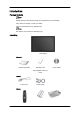
Introduction Package Contents Note Please make sure the following items are included with your LCD Display. If any items are missing, contact your dealer. Contact a local dealer to buy optional items. Note This stand is not for the Floor Standing Type.
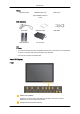
Introduction Others Remote Control Batteries (AAA X 2) HDD Cover (Not available in all locations) Sold separately DVI Cable Wall Mount KIT Semi Stand KIT TV tuner box LAN Cable Note • You can purchase and connect a separate network box or TV tuner box. For information on how to use these, refer to their respective user manuals. • You can only connect one external box. Your LCD Display Front MENU button [MENU] Opens the on-screen menu and exits from the menu.
Introduction Moves from one menu item to another vertically or adjusts selected menu values. Adjust buttons (Left-Right buttons) / Volume buttons Moves from one menu item to another horizontally or adjusts selected menu values. When OSD is not on the screen, push the button to adjust volume. ENTER button [ENTER] Activates a highlighted menu item. SOURCE button [SOURCE] Switches from PC mode to Video mode.
Introduction POWER S/W ON [ │ ] / OFF [O] Switches the LCD Display On/Off. POWER IN The power cord plugs into the LCD Display and the wall plug. RS232C OUT/IN (RS232C Serial PORT) MDC(Multiple Display Control) Program Port DVI / PC / HDMI IN [DVI/PC/HDMI AUDIO IN] (PC/DVI/HDMI Audio Connection Terminal (Input)) DVI / PC / HDMI IN [HDMI] Connect the HDMI terminal at the back of your LCD Display to the HDMI terminal of your digital output device using a HDMI cable.
Introduction Using a DVI Cable (DVI-D to DVI-D) - DVI mode (Digital PC) DC OUT [5V/1.5A] Connect this to the POWER connector of a TV tuner box or network box. AV IN [VIDEO] (VIDEO Connection Terminal) Connect the [ VIDEO ] terminal of your monitor to the video output terminal of the external device using a VIDEO cable.
Introduction Kensington Lock The Kensington Lock is a device used to physically fix the system when using it in a public place. The locking device has to be purchased separately. The appearance and locking method may differ from the illustration depending on the manufacturer. Refer to the manual provided with the Kensington Lock for proper use. The locking device has to be purchased separately. Note The location of the Kensington Lock may be different depending on its model.
Introduction POWER OFF Number Buttons DEL button + VOL MUTE TV/DTV MENU INFO COLOR BUTTONS TTX/MIX STILL AUTO S.MODE MDC LOCK SOURCE ENTER/PRE-CH CH/P D.MENU GUIDE RETURN Up-Down Left-Right buttons EXIT SRS MagicInfo P.MODE DUAL/MTS PIP SWAP 1. POWER Turns the product On. 2. Off Turns the product Off. 3. Number Buttons Press to change the channel. 4. DEL The "-" button operates only for DTV. It is used to select MMS (multi-channel) for a DTV.
Introduction 5. + VOL - Adjusts the audio volume. 6. Pauses (mutes) the audio output temporarily. This is displayed on the lower left corner of the screen. The audio resumes if MUTE or - VOL + is pressed in the Mute mode. MUTE 7. TV/DTV Selects the TV and DTV mode directly. 8. MENU Opens the on-screen menu and exits from the menu or closes the adjustment menu. 9. Activates a highlighted menu item. 10. INFO 11.COLOR BUTTONS TTX/MIX 12.
Introduction 23. RETURN Returns to the previous menu. 24. Up-Down Left-Right buttons Moves from one menu item to another horizontally, vertically or adjusts selected menu values. 25. Exits from the menu screen. EXIT SRS 26. Selects SRS TruSurround XT mode. 27.MagicInfo MagicInfo Quick Launch Button. 28. P.MODE When you press this button, current picture mode is displayed on the lower center of the screen. AV / HDMI / TV : P.
Introduction Mechanical Layout (400TSn-2) Mechanical Layout Installation VESA Bracket • When installing VESA, make sure to comply with the international VESA standards. • Purchasing VESA Bracket and Installation Information : Please contact your nearest SAMSUNG Distributor to place an order. After your order is placed, installation professionals will visit you and install the bracket. • At least 2 persons are needed in order to move the LCD Display.
Introduction Dimensions Notice For securing the bracket on a wall, use only machine screws of 6 mm diameter and 8 to 12 mm length. Wall Bracket Installation • Contact a technician for installing the wall bracket. • SAMSUNG Electronics is not responsible for any damages to the product or harm to customers when the installation is done by the customer. • This product is for installing on cement walls. The product may not stay in place when installed on plaster or wood.
Introduction 1. Insert and tighten the Captive Screw in the direction of the arrow. When done, mount the wall bracket on the wall. There are two hinges(left and right). Use the correct one. 2. A- Captive Screw B- Wall Bracket C- Hinge (Left) D- Hinge (Right) Before drilling into the wall, check if the length between the two locking holes at the back of the product is correct. If the length is too short or long, loosen all or some of the 4screws on the wall bracket to adjust the length. A3.
Introduction To mount the product on the wall bracket The shape of the product may vary depending on the model. (The assemblies of the plastic hanger and the screw are the same) 1. Remove the 4 screws on the back of the product. 2. Insert the screw B into the plastic hanger. Notice 3. • Mount the product on the wall bracket and make sure it is properly fixed to the left and right plastic hangers. • Be careful when installing the product on the bracket as fingers can be caught in the holes.
Introduction 4. Remove safety pin (3) and insert the 4 product holders into the corresponding bracket holes (1). Then place the product(2) so that it is firmly fixed to the bracket. Make sure to re-insert and tighten the safety pin (3) to securely hold the product to the bracket. A- LCD Display B- Wall Bracket C- Wall Wall Bracket Angle Adjustment Adjust the bracket angle to -2° before installing it on the wall. 1. Fix the product to the wall bracket. 2.
Introduction Make sure to use the top center, and not the left or the right side of the product to adjust the angle. Mechanical Layout (460TSn-2) Mechanical Layout Installation VESA Bracket • When installing VESA, make sure to comply with the international VESA standards. • Purchasing VESA Bracket and Installation Information : Please contact your nearest SAMSUNG Distributor to place an order. After your order is placed, installation professionals will visit you and install the bracket.
Introduction Dimensions Notice For securing the bracket on a wall, use only machine screws of 6 mm diameter and 8 to 12 mm length. Wall Bracket Installation • Contact a technician for installing the wall bracket. • SAMSUNG Electronics is not responsible for any damages to the product or harm to customers when the installation is done by the customer. • This product is for installing on cement walls. The product may not stay in place when installed on plaster or wood.
Introduction There are two hinges(left and right). Use the correct one. 2. A- Captive Screw B- Wall Bracket C- Hinge (Left) D- Hinge (Right) Before drilling into the wall, check if the length between the two locking holes at the back of the product is correct. If the length is too short or long, loosen all or some of the 4screws on the wall bracket to adjust the length. A3. Length between the two locking holes Check the installation diagram and mark the drill points on the wall. Use the 5.
Introduction To mount the product on the wall bracket The shape of the product may vary depending on the model. (The assemblies of the plastic hanger and the screw are the same) 1. Remove the 4 screws on the back of the product. 2. Insert the screw B into the plastic hanger. Notice 3. • Mount the product on the wall bracket and make sure it is properly fixed to the left and right plastic hangers. • Be careful when installing the product on the bracket as fingers can be caught in the holes.
Introduction 4. Remove safety pin (3) and insert the 4 product holders into the corresponding bracket holes (1). Then place the product(2) so that it is firmly fixed to the bracket. Make sure to re-insert and tighten the safety pin (3) to securely hold the product to the bracket. A- LCD Display B- Wall Bracket C- Wall Wall Bracket Angle Adjustment Adjust the bracket angle to -2° before installing it on the wall. 1. Fix the product to the wall bracket. 2.
Introduction Make sure to use the top center, and not the left or the right side of the product to adjust the angle.
Connections Connecting a Computer Using a Power cord with Earth • In the event of failure, the earth lead may cause electric shock. Make sure to wire the earth lead in correctly, before connecting the AC power. When un-wiring the earth lead, make sure to disconnect the AC power in advance. Note AV input devices such as DVD players, VCRs or camcorders as well as your computer can be connected to the LCD Display.
Connections Connect the audio cable for your LCD Display to the audio port on the back of your computer. Note • Turn on both your computer and the LCD Display. • The DVI cable is optional. • Contact a local SAMSUNG Electronics Service Center to buy optional items. Connecting to Other devices Using a Power cord with Earth • In the event of failure, the earth lead may cause electric shock. Make sure to wire the earth lead in correctly, before connecting the AC power.
Connections Connecting to a Camcorder 1. Locate the AV output jacks on the camcorder. They are usually found on the side or back of the camcorder. Connect a set of audio cables between the AUDIO OUTPUT jacks on the camcorder and the AV AUDIO IN [L-AUDIO-R] on the LCD Display . 2. Connect a video cable between the VIDEO OUTPUT jack on the camcorder and the AV IN [VIDEO] on the LCD Display . 3.
Connections Connecting Using a DVI to HDMI Cable Note • Connect the DVI output terminal of a digital output device to the HDMI terminal of the LCD Display using a DVI to HDMI cable. • Connect the red and white jacks of an RCA to stereo (for PC) cable to the same colored audio output terminals of the digital output device, and connect the opposite jack to the DVI / PC / HDMI AUDIO IN terminal of the LCD Display.
Connections Note Connect the LAN cable. Connecting a USB device Using a Power cord with Earth • In the event of failure, the earth lead may cause electric shock. Make sure to wire the earth lead in correctly, before connecting the AC power. When un-wiring the earth lead, make sure to disconnect the AC power in advance. Note AV input devices such as DVD players, VCRs or camcorders as well as your computer can be connected to the LCD Display.
Using the Software Monitor Driver Note When prompted by the operating system for the monitor driver, insert the CDROM included with this monitor. Driver installation is slightly different from one operating system to another. Follow the directions appropriate for the operating system you have. Prepare a blank disk and download the driver program file at the Internet web site shown here. Internet web site : http://www.samsung.com/ (Worldwide) Installing the Monitor Driver (Automatic) 1.
Using the Software Note This monitor driver is under certifying MS logo, and this installation doesn't damage your system. The certified driver will be posted on Samsung Monitor homepage. http://www.samsung.com/ Installing the Monitor Driver (Manual) Microsoft® Windows Vista™‚ Operating System 1. Insert your Manual CD into your CD-ROM drive. 2. (Start) and "Control Panel". Then, double-click on "Appearance and PersonalClick ization". 3. Click "Personalization" and then "Display Settings". 4.
Using the Software If the message "Windows needs..." is displayed, as shown in the figure below, click "Continue". Note This monitor driver is under certifying MS logo, and this installation doesn't damage your system. The certified driver will be posted on Samsung Monitor homepage. 6. Click "Update Driver..." in the "Driver" tab. 7. Check the "Browse my computer for driver software" checkbox and click "Let me pick from a list of device drivers on my computer". 8. Click "Have Disk...
Using the Software 9. Select the model that matches your monitor from the list of monitor models on the screen, and click "Next". 10. Click "Close" → "Close" → "OK" → "OK" on the following screens displayed in sequence.
Using the Software 1. Insert CD into the CD-ROM drive. 2. Click "Start" → "Control Panel" then click the "Appearance and Themes" icon. 3. Click "Display" icon and choose the "Settings" tab then click "Advanced...". 4. Click the "Properties" button on the "Monitor" tab and select "Driver" tab. 5. Click "Update Driver..." and select "Install from a list or..." then click "Next" button. 6. Select "Don't search, I will..." then click "Next" and then click "Have disk".
Using the Software 7. Click the "Browse" button then choose A:(D:\Driver) and choose your monitor model in the model list and click the "Next" button. 8. If you can see following message window, then click the "Continue Anyway" button. Then click "OK" button. Note This monitor driver is under certifying MS logo, and this installation doesn't damage your system. The certified driver will be posted on Samsung Monitor homepage. http://www.samsung.com/ 9.
Using the Software 10. Monitor driver installation is completed. Microsoft® Windows® 2000 Operating System When you can see "Digital Signature Not Found" on your monitor, follow these steps. 1. Choose "OK" button on the "Insert disk" window. 2. Click the "Browse" button on the "File Needed" window. 3. Choose A:(D:\Driver) then click the "Open" button and then click "OK" button. How to install 1. Click "Start", "Setting", "Control Panel". 2. Double click the "Display" icon. 3.
Using the Software 4. Select the "Monitor" tab. 5. Click the "Change" button in the "Monitor Type" area. 6. Choose "Specify the location of the driver". 7. Choose "Display a list of all the driver in a specific location..." then click "Next" button. 8. Click the "Have Disk" button. 9. Specify A:\(D:\driver) then click "OK" button. 10. Select "Show all devices" and choose the monitor that corresponds to the one you connected to your computer and click "OK". 11.
Using the Software 10. You have finished setting up your monitor. Execute X-Window after setting other requested hardware. IRTOUCH IRTouch Screen Control Panel Double click the mark on the tabletop (as the following indication), or follow "Start" -> "All programs" -> "IRTouchSystems", and then click "IR TouchScreen Control Panel" and go to the Control Panel of the touchscreen as following. General Control Panel menu 1.
Using the Software 2. Select the touchscreen you want in the list and Click [Calibrate]. After calibration, the item "Calibrated" will show "Yes". Calibration compromising of steps: select a touchscreen in the information list, then click "calibrate" button when the calibration window shows up. Calibration is done by clicking on 4 calibration points so that user only clicks the center of the bull's-eye in sequence.
Using the Software Modes Setting 1. Click on touch Mouse single click event happens immediately at the point when the finger contact the touchscreen, not for dragging objects. In this mode the touchscreen responds fastest, it's usually used for big button applications. 2.
Using the Software the pop-up time is either fast or slow. Notice: the higher the value, the slower the popup time. "Delay" unit is "millisecond". The "area" is used for adjusting the jitter-range of the touch surface within limit of error (unit: pixel). The higher the value, the wider the jitter-range. Right Click menu will pop up so long as the finger contacts the screen for a while within the range. 7. Enable Double Click Same as the function of Mouse Double Click.
Using the Software 2. Click [Change Port] to set and change setting of the selected Serial Port. Attachment The general setting of touchscreen Select "Mouse Emulation" mode, then choose "Enable Touch" Send Right ClickEnable DoubleClick. In general functions of Enable Delay Touch and False touch rejection may not selected to avoidslowing the touch response. It is proved null if you quickly click or drag the touch point.
Using the Software Installment 1. Send Right Click : To enable right-click function (default). Click and press on any area on the screen for two second, the right-click menu will pop-up. Right-click is only available in Mouse Emulation mode. The “Delay” value is 1000(1second); The “Area” value is set to 32px at optimum. 2. Enable Double Click : Same as the function of Mouse Double Click. Double click on the same setting area of objects in a short time may open up the object.
Using the Software Specification 1. Each value should be gradually set in "Delay Touch Settings" after fulfillment of "Enable Delay Touch". "Delay" is set to 40 and "Area" to 16. 2. Enter count : It means how many times you click to approach the setting value within 3 seconds. Then driver will install the function of "False touch rejection" where quick click or scratch will be considered void except the touch point on the active area for quite a while. 3.
Introduction A Multiple Display Control (MDC) is an application allowing various displays to be easily and simultaneously operated on a PC. RS-232C, a standard of serial communication, is used for the communication between a PC and a display. Therefore, a serial cable should be connected between the serial port on a PC and the serial port on a display. Main Screen Click Start > Program > Samsung > MDC System to start the program. Select a set to see the volume of the selected set within the slider.
Main Icons Select Button Remocon Info Grid Safety Lock Display Selection Port Selection Control Tools 1. Use the main icons to switch into each screen. 2. Allows you to enable or disable the remote control signal receiving function of the display unit. 3. Set the Safety Lock function. When setting the Lock function, you can only operate power and lock buttons on the remote control and set. 4. The setting for the PC Serial Port can change. The original value is COM1. 5.
1. The Multiple Display Control is originally set to COM1. 2. If any port other than COM1 is used, COM1 through COM4 can be selected in the Port Selection Menu. 3. If the exact port name that is connected to the LCD Display using a serial cable is not selected, communication will be unavailable. 4. The selected port is stored in the program and used for the next program as well. Power Control 1. Click Power Control of the main icons and the Power Control screen appears.
Info Grid shows some basic information necessary to Power Control. 1) (Power Status) 2) Input 3) Image Size 4) On Timer 5) Off Timer 2. Use the Select All button or Check Box to choose a display to control. Power Control allows controlling some of the functions of the selected display.
- Turns the power of the selected display On/Off. 2) Volume - Controls the volume level of the selected display. It receives the volume value of the selected display from the sets and displays it in the slider. (When you cancel the selection or choose Select All, the value returns to the default value 10) 3) (Mute On/Off) - Turns on/off the Mute function of the selected display. When selecting one set at a time, turn on the Mute function for the selected set.
Info Grid shows some basic information necessary to Input Source Control. 1) PC - Changes the Input Source of the selected display to PC. 2) BNC - Changes the Input Source of the selected display to BNC. 3) DVI - Changes the Input Source of the selected display to DVI. 4) TV - Changes the Input Source of the selected display to TV. 5) DTV - Changes the Input Source of the selected display to DTV. 6) AV - Changes the Input Source of the selected display to AV.
Info Grid shows some basic information necessary to Image Size Control. 1) ( Power Status) - Shows the power status of the current display. 2) Image Size - Shows the current Image Size of the display in use. 3) Input - Shows the current Input Source of the display in use. 4) Info Grid displays only the displays whose Input Source is PC, BNC, DVI. 5) PC Source - When you click Image Size, the PC Source tab first appear. - The Image Size Control button controls Image Size available for PC, BNC, DVI.
Info Grid shows some basic information necessary to Image Size Control. 1) Click the Video Source tab to adjust Image Size for TV, AV, S-Video, Component, DVI(HDCP), HDMI, DTV. Click Select All or use Check Box to select a display to control. 2) Info Grid displays only the display having TV, AV, S-Video, Component or DVI(HDCP) as input source. 3) Switch Image Size of the selected display randomly.
Info Grid shows some basic information necessary to Time Control. 1) Current Time - Set the current time for the selected display (PC Time). - To change the current time, first change the PC Time. 2) On Time Setup - Set the Hour, Minute, AM/PM of On Time Setup, Status, Source, Volume of the selected display. 3) Off Time Setup - Set the Hour, Minute, and AM/PM, Status for Off Time Setup of the selected display. 4) Shows the On Time settings. 5) Shows the Off Time settings.
Info Grid shows some basic information necessary to PIP Size Control. 1) PIP Size - Shows the current PIP Size of the display in use. 2) OFF - Turns off the PIP of the selected display. 3) Large - Turns on the PIP of the selected display and changes the size to Large. 4) Small - Turns on the PIP of the selected display and changes the size to Small. 5) Double 1 - Turns on the PIP of the selected display and changes the size to Double 1.
Info Grid shows some basic information necessary to PIP Source Control. 1) PIP Source - PIP Source can be controlled with turning on the LCD Display power. 2) PC - Changes the source of the PIP of the selected display to PC. 3) BNC - Changes the source of the PIP of the selected display to BNC. 4) DVI - Changes the source of the PIP of the selected display to DVI. 5) AV - Changes the source of the PIP of the selected display to AV.
Info Grid shows some basic information necessary to Settings Control. When each function is selected, the set value of the selected function is displayed in the slide.When selected, each function fetches the value for the set and displays it on the slide bar. When "Select All" is chosen, the default value is displayed. Changing a value in this screen will automatically change the mode to "CUSTOM." 1) Picture - Available only for TV, AV, S-Video, Component, HDMI, DTV.
1. Click Settings of the main icons and the Settings Control screen appears. Info Grid shows some basic information necessary to Settings Control. When each function is selected, the set value of the selected function is displayed in the slide. When selected, each function fetches the value for the set and displays it on the slide bar. When "Select All" is chosen, the default value is displayed. Changing a value in this screen will automatically change the mode to "CUSTOM.
Settings Audio 1. Click Settings of the main icons and the Settings Control screen appears. Info Grid shows some basic information necessary to Settings Control. When each function is selected, the set value of the selected function is displayed in the slide. When selected, each function fetches the value for the set and displays it on the slide bar. When "Select All" is chosen, the default value is displayed. Changing a value in this screen will automatically change the mode to "CUSTOM.
Info Grid shows some basic information necessary to Settings Control. 1) Image Lock - Available only for PC, BNC. 2) Coarse - Adjusts Coarse of the selected display. 3) Fine - Adjusts Fine of the selected display. 4) Position - Adjusts Position of the selected display. 5) Auto Adjustment - Self-Adjust to the incoming PC signal. The Input source of MagicInfo works only on MagicInfo model. The Input source of TV works only on TV model.
An "Info Grid" showing several basic data items appears. 1) Maintenance - Allows the Maintenance Control function for all input sources. 2) Auto Lamp Control - Automatically adjusts the backlight of the selected display at a specified time. The Manual Lamp Control automatically turns off if you adjust using the Auto Lamp Control. 3) Manual Lamp Control - Allows you to adjust the backlight of the selected display regardless of the time.
1) Scroll - This function is used to remove the afterimages that occur when a still screen is displayed on the selected display for a long time. 2) Pixel Shift - This allows the screen to be moved finely at the specified time interval. 3) Safety Screen - The Safety Screen function is used to prevent afterimages from occurring when a still screen is displayed on the monitor for a long time.
1) Video Wall - A Video Wall is a set of video screens that are connected together, so that each screen shows a part of the whole picture or so that the same picture is repeated on each screen. 2) Video Wall (Screen divider) - The screen can be divided into. You can select a number of screens with a different layout when dividing. z Select a mode from Screen divider. z Select a display from Display Selection. z The place will be set up by pressing a number in the selected mode.
- Check the displays to see if any of the other displays connected have the same ID. If more than one displays have the same ID, those displays are not properly detected by the program due to data conflict. - Check if the Display Set ID is a number between 0 and 25. (Adjust using the Display menu) Note : A Display Set ID must be a value between 0 and 25 . 2. The display you wish to control does not appear on the other Control Info Grids - Check to see if the display power is ON.
Adjusting the LCD Display Input Available Modes • PC / DVI • AV • HDMI • MagicInfo Note The TV menu is available when a TV tuner box is installed. Source List MENU → ENTER → [Input] → ENTER → [Source List] → , → ENTER Use to select PC, DVI or other external input sources connected to the LCD Display. Use to select the screen of your choice. 1. PC 2. DVI 3. AV 4. HDMI 5. MagicInfo Note • The direct button on the remote control is the 'SOURCE' button.
Adjusting the LCD Display → , → ENTER Name the input device connected to the input jacks to make your input source selection easier. 1. PC 2. DVI 3. AV 4. HDMI Picture [PC / DVI / MagicInfo Mode] Available Modes • PC / DVI • AV • HDMI • MagicInfo Note The TV menu is available when a TV tuner box is installed.
Adjusting the LCD Display (Not available in Dynamic Contrast mode of On.) 1. Entertain High brightness For watching motion pictures such as a DVD or VCR. 2. Internet Medium brightness For working with a mixture of images such as texts and graphics. 3. Text Normal brightness For documents or works involving heavy text. 4. Custom Although the values are carefully chosen by our engineers, the pre-configured values may not be comfortable to your eyes depending on your taste.
Adjusting the LCD Display Sharpness MENU → → ENTER → [Picture] → [Sharpness] → , → ENTER → [Custom] → → → ENTER → → ENTER Adjusts the Sharpness. Color Tone MENU → → , → ENTER → [Picture] → → →ENTER → [Color Tone] → ENTER The color tones can be changed. (Not available in Dynamic Contrast mode of On.) 1. Off 2. Cool 3. Normal 4. Warm 5. Custom Note If you set the Color Tone to Cool, Normal, Warm, or Custom, the Color Temp function is disabled.
Adjusting the LCD Display Red MENU → → [Red] → , → ENTER → [Picture] → → → → ENTER → [Color Control] → ENTER → ENTER Green MENU → → ENTER → [Picture] → → → → ENTER → [Color Control] → → ENTER → [Green] → , → ENTER Blue MENU → → ENTER → [Picture] → ENTER → [Blue] → , → → → ENTER → [Color Control] → → → → ENTER Color Temp. MENU → → , → ENTER → [Picture] → → → → ENTER → [Color Temp.] → ENTER Color Temp is a measure of the 'warmth' of the image colors.
Adjusting the LCD Display Coarse MENU → → ENTER → [Picture] → → [Coarse] → , → → → → ENTER → [Image Lock] → ENTER → ENTER Removes noise such as vertical stripes. Coarse adjustment may move the screen image area. You may relocate it to the center using the horizontal control menu. Fine MENU → → ENTER → [Picture] → ENTER → [Fine] → , → → → → ENTER → [Image Lock] → → → ENTER Removes noise such as horizontal stripes.
Adjusting the LCD Display (Not available in Dynamic Contrast mode of On.) Note The direct button on the remote control is the 'AUTO' button. Signal Balance This is used to make up for the weak RGB signal transmitted by a long signal cable. MENU → ance] → ENTER → [Picture] → → → → → → → ENTER → [Signal Bal- (Available in PC mode only) (Not available in Dynamic Contrast mode of On.
Adjusting the LCD Display 3. B-Gain MENU → → ENTER → [Picture] → → → → → → → ENTER → [Signal Balance] → ENTER → → [Signal Control] → → → ENTER→ [B-Gain] → , 4. → ENTER R-Offset MENU → → ENTER → [Picture] → → → Balance] → ENTER → → [Signal Control] → → → , 5. → → → → ENTER → [Signal → → ENTER→ [R-Offset] → ENTER G-Offset MENU → → ENTER → [Picture] → → → → → → → ENTER → [Signal Balance] → ENTER → → [Signal Control] → → → → → ENTER→ [G-Offset] → , 6.
Adjusting the LCD Display 1. 16:9 2. 4:3 Dynamic Contrast MENU → Contrast] → , → ENTER → [Picture] → → → → → → → → → ENTER → [Dynamic → ENTER Dynamic Contrast automatically detects the distribution of the visual signal and adjusts to create an optimum contrast. 1. Off 2. On Picture [ AV / HDMI Mode] Available Modes • PC / DVI • AV • HDMI • MagicInfo Note The TV menu is available when a TV tuner box is installed.
Adjusting the LCD Display The LCD Display has four automatic picture settings ("Dynamic", "Standard", "Movie" and "Custom") that are preset at the factory. Dynamic, Standard, Movie, or Custom can be activated. (Not available in Dynamic Contrast mode of On.) 1. Dynamic 2. Standard 3. Movie 4. Custom Note The direct button on the remote control is the 'P.MODE' button. Custom By using the on-screen menus, the contrast and brightness can be changed to your personal preference.
Adjusting the LCD Display Color MENU → [Color] → , → ENTER → [Picture] → → ENTER → [Custom] → → → → ENTER → → ENTER → [Custom] → → → → → ENTER → ENTER Adjusts the picture Color. Tint MENU → → [Tint] → , → ENTER → [Picture] → → ENTER Adds a natural tone to the display. Color Tone MENU → → , → ENTER → [Picture] → → → ENTER → [Color Tone] → ENTER The color tones can be changed. The individual Color components are also user adjustable. (Not available in Dynamic Contrast mode of On.) 1.
Adjusting the LCD Display Color Temp. MENU → → , → ENTER → [Picture] → → → → ENTER → [Color Temp.] → ENTER Color temp is a measure of the 'warmth' of the image colors. (Not available in Dynamic Contrast mode of On.) Note This function is only enabled if the Color Tone is set to Off. Size MENU → → , → ENTER → [Picture] → → → → → ENTER → [Size] → ENTER The Size can be switched. 1. 16:9 2. Zoom 1 3. Zoom 2 4. 4:3 5. Just Scan (Not available in Dynamic Contrast mode of On.
Adjusting the LCD Display → , → ENTER Turns the Digital Noise Reduction feature Off/On. The Digital Noise Reduction feature allows you to enjoy clearer and crisper images. 1. Off 2. On Film Mode MENU → → , → ENTER → [Picture] → → → → → → → ENTER → [Film Mode ] → ENTER The Film Mode feature offers you a theater-quality viewing experience. (In HDMI mode, this function can be available when the input signal is interlaced scan; it cannot be available with progressive scan signal.) 1. Off 2.
Adjusting the LCD Display Sound Available Modes • PC / DVI • AV • HDMI • MagicInfo Note The TV menu is available when a TV tuner box is installed. Mode MENU → → , → → ENTER → [Sound] → ENTER → [Mode] → ENTER The LCD Display has a built-in high fidelity stereo amplifier. 1. Standard Selects Standard for the standard factory settings. 2. Music Selects Music when watching music videos or concerts. 3. Movie Selects Movie when viewing movies. 4.
Adjusting the LCD Display Note • You can hear the sound even when sound value is set to 0. • If you adjust sound using Custom function, Mode will turn to Custom mode. Bass MENU → → , → → ENTER → [Sound] → → ENTER → [Custom ]→ENTER→ [Bass] → ENTER Emphasizes low frequency audio. Treble MENU → → , → → ENTER → [Sound] → → ENTER → [Custom ]→ →ENTER→ [Treble] → ENTER Emphasizes high frequency audio.
Adjusting the LCD Display SRS TS XT MENU → → , → → ENTER → [Sound] → → → → ENTER → [SRS TS XT] → ENTER SRS TS XT is a patented SRS technology that solves the problem of playing 5.1 multichannel content over two speakers. TruSurround delivers a compelling, virtual surround sound experience through any two-speaker playback system, including internal television speakers. It is fully compatible with all multichannel formats. 1. Off 2.
Adjusting the LCD Display You can choose one of 13 languages. Note The language chosen affects only the language of the OSD. It has no effect on any software running on the computer. Time Selects from one of 4 time settings, Clock Set, Sleep Timer, On Timer, and Off Timer. MENU → → → → ENTER → [Setup] → → ENTER → [Time ] Clock Set MENU → Set] → , / , → → → ENTER → [Setup] → → ENTER → [Time ] → ENTER→ [Clock → ENTER Current Time Setting.
Adjusting the LCD Display 5. 120 6. 150 7. 180 On Timer MENU → → → → ENTER → [Setup] → [On Timer] → , / , → ENTER → [Time ] → → → ENTER→ → ENTER Turns the LCD Display on automatically at a preset time. Controls the mode and the volume level at the time the LCD Display turns on automatically. Off Timer MENU → → → → ENTER → [Setup] → → [Off Timer] → , / , → ENTER → [Time ] → → → → ENTER → ENTER Turns the LCD Display off automatically at a preset time.
Adjusting the LCD Display Change the transparency of the background of the OSD. 1. High 2. Medium 3. Low 4. Opaque Safety Lock PIN MENU → → → → ENTER → [Setup] → → → → ENTER → [Safety Lock PIN ] → [0∼9, 0∼9, 0∼9, 0∼9] → [0∼9, 0∼9, 0∼9, 0∼9] → [0∼9, 0∼9, 0∼9, 0∼9] The password can be changed. Energy Saving MENU → → , → → → ENTER → [Setup] → → → → → ENTER → [Energy Saving] → ENTER This feature adjusts the power consumption of the unit in order to save energy. 1. Off 2.
Adjusting the LCD Display → , → ENTER When a DVD or set-top box is connected to your TV via HDMI, it may cause a degradation in the screen quality, such as an increase in the black level, a low contrast, or discoloration, etc., depending on the external device connected. In this case, adjust the screen quality of your TV by configuring the HDMI black level. 1. Normal 2.
Adjusting the LCD Display → , → ENTER The Format can be selected to see a divided screen. 1. Full Provides a full screen without any margins. 2. Natural Displays a natural image with the original aspect ratio intact. Horizontal MENU → → → → ENTER → [Setup] → → → → Wall ]→ → → ENTER → [Horizontal] → , → → ENTER → [Video → → → ENTER → [Video → → → ENTER → [Video → → ENTER Sets how many parts the screen should be divided horizontally. Five adjustment levels: 1, 2, 3, 4, and 5.
Adjusting the LCD Display The screen can be divided into several images. A number of screens can be selected with a different layout when dividing. • Select a mode in Screen Divider. • Select a display in Display Selection. • The selection will be set up by pressing a number in the selected mode. Safety Screen The Safety Screen function is used to prevent afterimages that may appear when a still picture is displayed on the screen over a long time.
Adjusting the LCD Display Horizontal Dot MENU → → → → ENTER → [Setup] → → → → → → → → ENTER → [Safety Screen] → ENTER → [Pixel Shift] → → ENTER → [Horizontal Dot] → , → ENTER Sets how many pixels the screen moves horizontally. Five adjustment levels: 0, 1, 2, 3, and 4. Vertical Line MENU → → → → ENTER → [Setup] → → → → → → → → ENTER → [Safety Screen] → ENTER → [Pixel Shift] → → → ENTER → [Vertical Line] → , → ENTER Sets how many pixels the screen moves vertically.
Adjusting the LCD Display You can set the timer for Screen Burn Protection. If you start the operation to erase any residual image, the operation will be performed for the set period of time and then automatically finish. 1. Off 2. On Mode MENU → → → → ENTER → [Setup] → → → → → → → → ENTER → [Safety Screen] → → ENTER → [Timer] → → ENTER → [Mode] → , → ENTER You can change the Safety Screen Type. 1. Scroll 2. Bar 3.
Adjusting the LCD Display Time MENU → → → → ENTER → [Setup] → → → → → → → → ENTER → [Safety Screen] → → ENTER → [Timer] → → → → ENTER → [Time] → , → ENTER Within the set period of time specify a time for execution. • Mode-Scroll : 1~5 sec • Mode-Bar, Eraser : 10~50 sec Scroll MENU → → → → ENTER → [Setup] → → → → → → → → ENTER → [Safety Screen] → → → ENTER → [Scroll] This function prevents after-images on the screen by moving all the pixels on the LCD according to a pattern.
Adjusting the LCD Display Eraser MENU → → → → ENTER → [Setup] → → → → → → → → ENTER → [Safety Screen] → → → → →ENTER → [Eraser] This function prevents after-images on the screen by moving a rectangular pattern.
Adjusting the LCD Display , → → ENTER Adjusts the Power On time for the screen. Caution: Set the Power On time to be longer to avoid overvoltage. Side Gray MENU → → → → ENTER → [Setup] → → → → ENTER → [Side Gray] , → → → → → → → → → ENTER Select the brightness of the grey for the screen background. 1. Off 2. Light 3. Dark Reset Reverts the product settings to factory defaults. The Reset function is only available when PC / DVI is being used.
Adjusting the LCD Display Note Available in PC mode only Note The Reset function is not available when Video Wall is On. Color Reset MENU → → → → ENTER → [Setup] → → → → → ENTER → [Reset ]→ → ENTER → [Color Reset ] → , → → → → → → → → ENTER OSD Rotation MENU → → → → ENTER → [Setup]→ → → → → → ENTER → [OSD Rotation ] → , → → → → → → → → → ENTER OSD Rotate 1. Landscape 2.
Adjusting the LCD Display Multi Control Available Modes • PC / DVI • AV • HDMI • MagicInfo Multi Control Assigns an individual ID to the SET. MENU → → → → → ENTER → [Multi Control ] → ENTER → , → [0~9] • ID Setup Assigns distinctive IDs to the SET. • ID Input Use to select the transmitter functions of the individual SET. Only a SET where the ID corresponds to the transmitter setting becomes activated.
Adjusting the LCD Display • Do not unplug the LAN cable used for the network (ex: video display). Otherwise, the program (MagicInfo) may stop. If you do unplug the cable, restart the system. • Do not unplug the LAN cable used by an USB device (ex: video display). Otherwise, the program (MagicInfo) may stop. • To access other sources, press the SOURCE button in MagicInfo. • The preset password for the LCD Display is "000000".
Adjusting the LCD Display 1. Select MagicInfo in the Source List menu. 2. The MUISetup screen appears. Select the language you want to use. 3. Press the Install button. If you select Do not show again and click the Install button, the Scheduler screen is displayed after rebooting. 4. Connect your keyboard and mouse and press the “ALT + F12” keys on your keyboard. 5. The Windows Desktop is displayed and the MagicInfo icon (the image will be inserted) appears. Move the cursor over the icon.
Adjusting the LCD Display Note To finish the MagicInfo, press ALT + F12. Photo The JPEG, BMP file format are supported. Auto Automatically fits the image to the window. Original Shows the properties of the original file.
Adjusting the LCD Display Slide Show Displays the properties of the original file as they are. Interval Controls the time intervals between image files for a slide show.
Adjusting the LCD Display Rotation Displays an image file by turning it clockwise by 90 degrees. Zoom Displays a reduced picture.
Adjusting the LCD Display Close Closes the image control Menu. Music The MP3 file format is supported. Movie The MPEG1, WMV file format are supported.
Adjusting the LCD Display Play Plays a movie file. Full Size Plays a movie file in full screen.
Adjusting the LCD Display OFFICE / HTML PPT(Power Point), DOC(MS Word), XLS(MS Excel), PDF, HTML, HTM files are displayed. Note • Install the proper viewer(freeware) program to see the MS Office(Word, Excel, Power Point) or PDF doucuments. Internet Connects to the Internet Setup Sets various functions in MagicInfo mode. A password must be entered to access Setup mode.
Adjusting the LCD Display Schedule View Displays a schedule. TCP/IP Changes the TCP/IP settings.
Adjusting the LCD Display Connection Modifies the network settings. Password The password can be changed. • The password should be between 6 and 12 characters in numeric format. (You should enter a password between 6 and 12 characters in numeric format) • If you enter the wrong password three times, the setup configuration is reset and a warning message appears from the server.
Adjusting the LCD Display • If you forget the password, enter Info, 8, 2 and 4 on the remote control to initialize the password. This will reset the previous settings of Setup mode. File Local : You can delete or copy files on both local and removable disks. Play Option You can set the repeat play and screen settings. Repeat : Determines the repeat option for playing movies and music. • None - Select No Repeat to play a movie or tune in the list only once.
Adjusting the LCD Display • File Repeat - Select Repeat File to play a movie or tune in the list repeatedly. • List Repeat - Select Repeat List to play movies or tunes in the list in sequence repeatedly. Rotation - Sets the picture orientation. • Landscape - Sets the screen resolution to 1366x768 pixels. • Portrait - Sets the screen resolution to 1366x768 pixels. EWF(Enhanced Write Filter) : Prevents change to and loss of the data saved on the disk.
Troubleshooting Self-Test Feature Check Note Check the following items yourself before calling for assistance. Contact a Service Center for problems that you cannot solve by yourself. Self-Test Feature Check 1. Turn off both your computer and the LCD Display. 2. Unplug the video cable from the back of the computer. 3. Turn on the LCD Display.
Troubleshooting • Do not use benzene, thinner or other flammable substances, or a wet cloth. • We recommend that a SAMSUNG cleansing agent is used to prevent damage to the screen. 2) Maintaining the Flat Panel Display Screen. Clean with a soft cloth (cotton flannel) smoothly. • Never use acetone, benzene or thinner. (They may cause flaws or deformation of the screen surface.) • The user will be required to pay costs and related expenses for repairing damages caused.
Troubleshooting A: Check if the signal cable between the computer and the LCD Display is securely connected. (Refer to Connecting a Computer) Problems related to the Screen Note Problems related to the LCD Display screen and their solutions are listed. Q: The screen is blank and the power indicator is off. A: Ensure that the power cord is firmly connected and the LCD Display is on. (Refer to the Connecting a Computer) Q: "Check Signal Cable" message.
Troubleshooting Q: The screen color is inconsistent. A: Adjust color using Custom under OSD Color Adjustment menu. Q: The color image is distorted by dark shadows. A: Adjust color using Custom under OSD Color Adjustment menu. Q: The color white is poor. A: Adjust color using Custom under OSD Color Adjustment menu. Q: The Power Indicator blinks. A: The LCD Display is currently saving the changes made in the settings to the OSD memory.
Troubleshooting A: Check the polarities (+/-) of the batteries. A: Check if the batteries are empty. A: Check if the power is on. A: Check if the power cord is securely connected. A: Check if a special fluorescent or neon lamp is on in the vicinity. Problems related to MagicInfo Note Making a Bootable USB Flash Disk. Q: Making a Bootable USB Flash Disk A: 1) You can turn a common 512-MB or bigger USB storage media into a bootable disk using a USB bootable disk creation tool.
Troubleshooting Set the resolution in the Control Panel → Appearance and Themes → Display → Screen Saver. Set the function in the BIOS-SETUP of the computer. (Refer to the Windows / Computer Manual). A: Windows ME/2000: Set the resolution at the Control Panel → Display → Screen Saver. Set the function in the BIOS-SETUP of the computer. (Refer to the Windows / Computer Manual).
Specifications General General Model Name SyncMaster 400TSn-2, 460TSn-2 LCD Panel Size Display area Pixel Pitch SyncMaster 400TSn-2 40 " Diagonal (101 cm) SyncMaster 460TSn-2 46 " Diagonal (116 cm) SyncMaster 400TSn-2 885.6 mm (H) X 498.15 mm (V) SyncMaster 460TSn-2 1018.08 mm (H) X 572.67 mm (V) SyncMaster 400TSn-2 0.46125 mm (H) X 0.46125 mm (V) SyncMaster 460TSn-2 0.46125 mm (H) x 0.46125 mm (V) Synchronization Horizontal 30 ~ 81 kHz Vertical 56 ~ 85 Hz Display Color 16.
Specifications Power Supply AC 100 - 240 V~ (+/- 10 %), 50/60 Hz ± 3 Hz Signal Cable 15pin-to-15pin D-sub cable, Detachable DVI-D to DVI-D connector, Detachable Dimensions (W x H x D) / Weight SyncMaster 400TSn-2 973.2 x 584.4 x 128.1 mm / 38.3 x 23.0 x 5.0 inch (Without Stand) 973.2 x 645.4 x 311.0 mm / 38.3 x 25.4 x 12.2 inch (With Stand) / 28.6 kg / 63.1 lbs SyncMaster 460TSn-2 1104.2 x 658.4 x 134.3 mm / 43.5 x 25.9 x 5.3 inch (Without Stand) 1104.2 x 720.0 x 311.0 mm / 43.5 x 28.3 x 12.
Specifications MagicInfo - Client Item Specification Remarks LAN 1 Gbps USB Keyboard/Mouse, Mass USB removable storage can Storage Device Compatibe supported. ble Contents Photo Supported File Format : BMP/JPEG 2274x1704 or less Music Supported File Format : MP3 Sound bandwidth : 50 Hz to 15 kHz Movie - MPEG1, WMV - Max 1280 x 720 30 fps File MS Office(Word, Excel, - Some files may not be supPower Point), HTML, PDF ported depending on the format or the version.
Specifications Preset Timing Modes If the signal transferred from the computer is the same as the following Preset Timing Modes, the screen will be adjusted automatically. However, if the signal differs, the screen may go blank while the power LED is on. Refer to the video card manual and adjusts the screen as follows. Display Mode Horizontal Frequency (kHz) Vertical Fre- Pixel Clock quency (Hz) (MHz) Sync Polarity (H/V) IBM, 640 x 350 31.469 70.086 25.175 +/- IBM, 640 x 480 31.469 59.940 25.
Information For Better Display Adjust the computer resolution and screen injection rate (refresh rate) on the computer as described below to enjoy the best picture quality. You can have an uneven picture quality on screen if the best picture quality is not provided for TFTLCD. • Resolution: 1920 x 1080 • Vertical frequency (refresh rate): 60 Hz TFT-LCD panels manufactured by using advanced semiconductor technology with a precision of 1ppm (one millionth) and above is used for this product.
Information Power Off, Screen Saver, or Power Save Mode • Turn the power off for 4 hours after 20 hours in use • Turn the power off for 2 hours after 12 hours in use • Set the Monitor to power off with the PC Display Properties Power Scheme. • Use a Screen saver if possible - Screen saver in one color or a moving image is recommended. Change the Color Information periodically Note Use Two different colors Rotate the Color Information with 2 different colors every 30 minutes.
Information • Avoid using a combination of characters and background color with large difference in luminance. Avoid using Grey colors, which can cause Image retention easily. Avoid: Colors with big difference in luminance (Black & White, Grey) Change the characters color periodically • Use Bright colors with little difference in luminance. - Cycle : Change the characters color and background color every 30 minutes • Every 30 minutes, change the characters with movement.
Information Note ( Please check CD's User Guide at "OSD Function", some model's will not available ) Apply the Screen Pixel function on Product • Apply the Screen Pixel function - Symptom: Dot with Black Color move up and down.
Information - Select method • Instruction Guide : OSD Menu -> Set Up -> Safety Screen -> Eraser • Time Interval : 1 ~ 10 hours ( Recommend : 1 ) • Time Period : 10 ~ 50 second ( Recommend : 50 ) Note ( Please check CD's User Guide at "OSD Function", some model's will not available )
Appendix Contact SAMSUNG WORLDWIDE Note If you have any questions or comments relating to Samsung products, please contact the SAMSUNG customer care center. North America U.S.A 1-800-SAMSUNG(726-7864) http://www.samsung.com/us CANADA 1-800-SAMSUNG(726-7864) http://www.samsung.com/ca MEXICO 01-800-SAMSUNG (726-7864) http://www.samsung.com/mx Latin America ARGENTINA 0800-333-3733 http://www.samsung.com/ar BRAZIL 0800-124-421 http://www.samsung.
Appendix Europe BELGIUM 02 201 2418 http://www.samsung.com/be (Dutch) http://www.samsung.com/ be_fr(French) CZECH REPUBLIC 800 (800-726786) SAMSUNG http://www.samsung.com/cz DENMARK 8 - SAMSUNG (7267864) http://www.samsung.com/dk EIRE 0818 717 100 http://www.samsung.com/ie FINLAND 30 - 6227 515 http://www.samsung.com/fi FRANCE 01 4863 0000 http://www.samsung.com/fr GERMANY 01805 SAMSUNG http://www.samsung.de (7267864, € 0.14/Min) HUNGARY 06-80-SAMSUNG (726-7864) http://www.samsung.
Appendix Asia Pacific AUSTRALIA 1300 362 603 http://www.samsung.com/au CHINA 800-810-5858 http://www.samsung.com/cn 400-810-5858 010-6475 1880 INDIA HONG KONG:3698 - 4698 http://www.samsung.com/hk 3030 8282 http://www.samsung.com/in 1-800-3000-8282 1800 110011 INDONESIA 0800-112-8888 http://www.samsung.com/id JAPAN 0120-327-527 http://www.samsung.com/jp MALAYSIA 1800-88-9999 http://www.samsung.com/my NEW ZEALAND 0800 SAMSUNG(0800 726 http://www.samsung.
Appendix Cycle. The inverse number of the Horizontal Cycle is called Horizontal Frequency. Unit: kHz Interlace and Non-Interlace Methods Showing the horizontal lines of the screen from the top to the bottom sequentially is called the Non-Interlace method while showing odd lines and then even lines in turn is called the Interlace method. The Non-Interlace method is used for the majority of monitors to ensure a clear image. The Interlace method is the same as that used in TVs.
Appendix Correct disposal of batteries in this product - Europe only (Applicable in the European Union and other European countries with separate battery return systems.) This marking on the battery, manual or packaging indicates that the batteries in this product should not be disposed of with other household waste at the end of their working life. Where marked, the chemical symbols Hg, Cd or Pb indicate that the battery contains mercury, cadmium or lead above the reference levels in EC Directive 2006/66.