SyncMaster 400CX-2, 400CXN-2, 460CX-2, 460CXN-2 LCD Display User Manual
Safety Instructions Notational Note These safety instructions must be followed to ensure your safety and prevent property damage. Make sure to read the instructions carefully and use the product in the correct manner. Warning / Caution Failure to follow directions noted by this symbol could result in bodily harm or damage to the equipment.
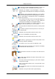
Safety Instructions Ensure that the power plug is plugged into the power outlet firmly and correctly. • Otherwise, this may result in fire. Do not forcefully bend or pull the power plug and do not place any heavy material on it. • Otherwise, this may result in fire. Do not connect multiple appliances to the same power outlet. • Otherwise, this may cause fire due to overheating. Do not disconnect the power cord while using the product.
Safety Instructions Keep heating appliances as far away from the power cord or the product as possible. • Otherwise, this may result in electric shock or fire. Do not install it in a badly ventilated location such as a bookcase or closet. • Otherwise, this may result in fire due to an increase in the internal temperature. When putting the product down, make sure to put it down softly. • Otherwise, this may result in damage to the screen display. Do not place the front of the product on the floor.
Safety Instructions Clean When cleaning the monitor case or the surface of the TFT-LCD screen, wipe with a slightly moistened, soft cloth. Do not spray cleaner directly onto the surface of the product. • Otherwise, this may result in the discoloration and distortion of the structure and the screen surface may peel off. When cleaning the power plug pins or dusting the power outlet, clean it with a dry cloth. • Otherwise, it may result in fire.
Safety Instructions When you drop the product or the case is broken, turn the power off and disconnect the power cord. Contact a Service Center. • Otherwise, this may result in electric shock or fire. If thunder or lightning is occurring, do not touch the power cord or antenna cable. • Otherwise, this may result in electric shock or fire. Do not try to move the monitor by pulling only the wire or the signal cable.
Safety Instructions When using headphones or earphones, do not turn the volume too high. • Having the sound too loud may damage your hearing. To avoid eyestrain, do not sit too close to the product. Take a rest for at least five (5) minutes after using the monitor for one (1) hour. This reduces eye fatigue. Do not install it in an unstable location such as an unstable rack or uneven surface or a location exposed to vibrations. • Otherwise, it may fall and cause personal injury and/or damage the product.
Safety Instructions Use only the specified standardized batteries, and do not use a new battery and a used battery at the same time. • Otherwise, the batteries may be damaged or cause fire, personal injury or damage due to a leakage of the internal liquid. The batteries (and rechargeable batteries) are not ordinary refuse and must be returned for recycling purposes. The customer is responsible for returning the used or rechargeable batteries for recycling.
Safety Instructions • Since the front part of the product is heavy, install the product on a level and stable surface. Do not put any heavy objects on the product. • This may result in personal injury and/or damage to the product.
Introduction Package Contents Note Please make sure the following items are included with your LCD Display. If any items are missing, contact your dealer. Contact a local dealer to buy optional items. Checking the Contents of the Package Remove the lock from the package box, as shown in the figure above. Lift up the package box by holding the grooves on both sides of the package box. Check the contents of the package. Remove the Styrofoam and vinyl cover.
Introduction Manuals Quick Setup Guide Warranty Card User's Guide (Not available in all locations) MagicInfo Software CD, MagicInfo Manual CD (Applicable to the CXN-2 model only) Cables Power Cord Others Remote Control HDD Cover (Applicable to the CXN-2 (Not available in all locamodel only) tions) Batteries (AAA X 2) Cleaning Cloth Sold separately DVI Cable LAN Cable 10 Wall Mount KIT
Introduction Sold separately (Applicable to the CXN-2 model only) Component to D-sub Cable Semi Stand KIT D-Sub Cable Note Cleaning Cloth is only provided for highly polished black products as a product feature. Your LCD Display Front MENU button [MENU] Opens the on-screen menu and exits from the menu. Also use to exit the OSD menu or return to the previous menu. Navigate buttons (Down-Up buttons) / Channel buttons Moves from one menu item to another vertically or adjusts selected menu values.
Introduction SOURCE button [SOURCE] Switches from PC mode to Video mode. Selects the input source that an external device is connected to. [PC] → [DVI] → [AV] → [Component] → [HDMI]→ [MagicInfo] → [TV] Note MagicInfo supports the CXN-2 model only. D.MENU Opens the on-screen D.MENU. Power button [ ] Use this button for turning the LCD Display on and off. Brightness Sensor (Optional) Automatically detects the surrounding brightness.
Introduction POWER S/W ON [ │ ] / OFF [O] Switches the LCD Display On/Off. POWER The power cord plugs into the LCD Display and the wall outlet. RS232C OUT/IN (RS232C Serial PORT) MDC(Multiple Display Control) Program Port RGB/COMPONENT IN (PC Video Connection Terminal) • Use a D-Sub Cable (15 pin D-Sub) PC mode (Analog PC) • Connect the RGB/COMPONENT IN port on the monitor to the COMPONENT port on the external device using the D-SUB to COMPONENT cable.
Introduction Use a DVI Cable (DVI-D to DVI-D) - DVI mode (Digital PC) DVI/RGB/HDMI AUDIO IN(PC/DVI/ HDMI(PC) Audio connection terminal(input)) AV / COMPONENT AUDIO IN [R- AUDIO- L] Connect the port of the DVD, VCR (DVD / DTV Set-Top Box) to the [ R- AUDIO - L] port of the LCD Display. DVI OUT • Connect a monitor to another monitor through a DVI cable. • Connect the DVI OUT port on the monitor to the HDMI IN port on the other monitor using the DVI to HDMI cable.
Introduction COMMON INTERFACE This contains information on CAM inserted in the CI slot and displays it. When not inserting CI CARD in some channels, Scramble Signal is displayed on the screen. You can install the CAM anytime whether the TV is ON or OFF. SERVICE This is a reserved terminal used for servicing. ANT IN Connect the CATV cable or TV antenna cable to the " ANT IN" port on the rear side of the LCD Display. Make sure to use a TV antenna cable (sold separately) as the antenna cable.
Introduction Kensington Lock The Kensington Lock is a device used to physically fix the system when using it in a public place. The locking device has to be purchased separately. The appearance and locking method may differ from the illustration depending on the manufacturer. Refer to the manual provided with the Kensington Lock for proper use. The locking device has to be purchased separately. Note The location of the Kensington Lock may be different depending on the model.
Introduction POWER OFF Number Buttons DEL / GUIDE button + VOL SOURCE D.MENU TOOLS Up-Down Left-Right buttons INFO COLOR BUTTONS TTX/MIX MTS/DUAL ENTER/PRE-CH MUTE CH/P TV MENU RETURN EXIT MagicInfo 1. POWER Turns the product On. 2. OFF Turns the product Off. 3. Number Buttons 4. DEL ton / GUIDE but- Press to change the channel. The "-" button is used to select Digital channels. For example, channel 4-1. Electronic Program Guide (EPG) display. - This fuction does not work for this LCD Display.
Introduction 8. TOOLS Use to quickly select frequently used functions. 9. Up-Down buttons Left-Right Moves from one menu item to another horizontally, vertically or adjusts selected menu values. INFO Current picture information is displayed on the upper left corner of the screen. 11. COLOR BUTTONS Press to add or delete channels and to store channels to the favorite channel list in the “Channel List” menu. 10. - This fuction does not work for this LCD Display. 12.
Introduction - This fuction does not work for this LCD Display. 18. MENU Opens the on-screen menu and exits from the menu or closes the adjustment menu. 19. RETURN Returns to the previous menu. 20. EXIT Exits from the menu screen. 21. MagicInfo MagicInfo Quick Launch Button. Mechanical Layout (400CX-2 ,400CXN-2) Mechanical Layout VESA Wall Mount Bracket Installation • When installing VESA, make sure to comply with the international VESA standards.
Introduction Dimensions Notice For securing the bracket on a wall, use only machine screws of 6 mm diameter and 8 to 12 mm length. Wall Bracket Installation • Contact a technician for installing the wall bracket. • SAMSUNG Electronics is not responsible for any damages to the product or persons if you elect to install the unit on your own. • This product is for installing on cement walls. The product may not stay in place when installed on plaster or wood.
Introduction 1. Insert and tighten the Captive Screw in the direction of the arrow. When done, mount the wall bracket on the wall. There are two hinges(left and right). Use the correct one. 2. A- Captive Screw B- Wall Bracket C- Hinge (Left) D- Hinge (Right) Before drilling into the wall, check if the length between the two locking holes at the back of the product is correct. If the length is too short or long, loosen all or some of the 4screws on the wall bracket to adjust the length. A- 3.
Introduction To mount the product on the wall bracket The shape of the product may vary depending on the model. (The assemblies of the plastic hanger and the screw are the same) 1. Remove the 4 screws on the back of the product. 2. Insert screw B into the plastic hanger. Notice 3. • Mount the product on the wall bracket and make sure it is properly fixed to the left and right plastic hangers. • Be careful when installing the product on the bracket as fingers can be caught in the holes.
Introduction 4. Remove safety pin (3) and insert the 4 product holders into the corresponding bracket holes (1). Then place the product(2) so that it is firmly fixed to the bracket. Make sure to re-insert and tighten the safety pin (3) to securely hold the product to the bracket. A- LCD Display B- Wall Bracket C- Wall Wall Bracket Angle Adjustment Adjust the bracket angle to -2° before installing it on the wall. 1. Fix the product to the wall bracket. 2.
Introduction Make sure to use the top center, and not the left or the right side of the product to adjust the angle. Mechanical Layout (460CX-2 ,460CXN-2) Mechanical Layout VESA Wall Mount Bracket Installation • When installing VESA, make sure to comply with the international VESA standards. • Purchasing VESA Bracket and Installation Information : Please contact your nearest SAMSUNG Distributor to place an order.
Introduction Dimensions Notice For securing the bracket on a wall, use only machine screws of 6 mm diameter and 8 to 12 mm length. Wall Bracket Installation • Contact a technician for installing the wall bracket. • SAMSUNG Electronics is not responsible for any damage to the product or persons if you elect to install the unit on your own. • This product is for installing on cement walls. The product may not stay in place when installed on plaster or wood.
Introduction When done, mount the wall bracket on the wall. There are two hinges(left and right). Use the correct one. 2. A- Captive Screw B- Wall Bracket C- Hinge (Left) D- Hinge (Right) Before drilling into the wall, check if the length between the two locking holes at the back of the product is correct. If the length is too short or long, loosen all or some of the 4screws on the wall bracket to adjust the length. A- 3.
Introduction To mount the product on the wall bracket The shape of the product may vary depending on the model. (The assemblies of the plastic hanger and the screw are the same) 1. Remove the 4 screws on the back of the product. 2. Insert the screw B into the plastic hanger. Notice 3. • Mount the product on the wall bracket and make sure it is properly fixed to the left and right plastic hangers. • Be careful when installing the product on the bracket as fingers can be caught in the holes.
Introduction 4. Remove safety pin (3) and insert the 4 product holders into the corresponding bracket holes (1). Then place the product(2) so that it is firmly fixed to the bracket. Make sure to re-insert and tighten the safety pin (3) to securely hold the product to the bracket. A- LCD Display B- Wall Bracket C- Wall Wall Bracket Angle Adjustment Adjust the bracket angle to -2° before installing it on the wall. 1. Fix the product to the wall bracket. 2.
Introduction Make sure to use the top center, and not the left or the right side of the product to adjust the angle.
Connections Connecting a Computer AV input devices such as DVD players, VCRs or camcorders as well as your computer can be connected to the LCD Display. For detailed information on connecting AV input devices, refer to the contents under Adjusting Your LCD Display. Connect the power cord for your LCD Display to the power port on the back of the LCD Display. Turn on the power switch. There are several ways to connect the computer to the monitor.
Connections Using the HDMI (digital) output on the graphics card. • Connect the HDMI IN port on the monitor to the HDMI port on the PC using the HDMI cable. Note • When the HDMI cable to the PC, ensure that you select HDMI from both the Source List and Edit Name before selecting PC or DVI device so that normal PC screen and sound can be outputted. • Note that sound is only available when connected according to the option 2 that follows.
Connections 1. Connect the CATV cable or TV antenna cable to the "ANT IN" port on the rear side of the LCD Display. Using a TV antenna cable (sold separately). • When using an interior antenna terminal: Check the antenna terminal on the wall first and connect the antenna cable. • When using an outdoor antenna: If you are using an outdoor antenna, use a professional for installation if possible.
Connections 2. Insert the CAM with the CI CARD installed into the common interface slot. (Insert the CAM in the direction of the arrow, right up to the end so that it is parallel with the slot.) 3. Check if you can see a picture on a scrambled signal channel. Connecting AV Devices 1. Connect the Video and Audio [R-AUDIO-L] port of the DVD, VCR or DTV Set-Top Box to the Video and Audio [R-AUDIO-L] LCD Display. 2. Play the DVD, VCR or Camcorder with a DVD disc or tape inserted. 3.
Connections • For an explanation of Component video, consult your DVD or external device's user manual. Connecting to a Camcorder 1. Locate the AV output jacks on the camcorder. They are usually found on the side or back of the camcorder. Connect a set of audio cables between the AUDIO OUTPUT jacks on the camcorder and the AV/COMPONENT AUDIO IN [R-AUDIOL] on the LCD Display . 2. Connect a video cable between the VIDEO OUTPUT jack on the camcorder and the AV IN [VIDEO] on the LCD Display . 3.
Connections Connecting Using a DVI to HDMI Cable 1. Connect the DVI output terminal of a digital output device to the HDMI IN terminal of the LCD Display using a DVI to HDMI cable. 2. Connect the red and white jacks of an RCA to stereo (for PC) cable to the same colored audio output terminals of the digital output device, and connect the opposite jack to the DVI / RGB AUDIO IN terminal of the LCD Display. Connecting Using a DVI Cable 1.
Connections Connecting a DTV Set Top (Cable/Satellite) Box 1. Connect the Component to D-sub cable(sold separately) to the product's RGB/ COMPONENT IN port and the COMPONENT - PR, Y, PB ports on the Set-Top Box. 2. Connect a set of audio cables between the AV/COMPONENT AUDIO IN [R-AUDIOL] on the LCD Display and the AUDIO OUT jacks on the Set Top Box. Note • Select Component using the SOURCE button on the front of the LCD Display or on the remote control.
Connections Connect the LAN cable. (CXN-2 model only) Connecting a USB device • You can connect USB devices such as a mouse or keyboard.
Using the Software Monitor Driver Note When prompted by the operating system for the monitor driver, insert the CD-ROM included with this monitor. Driver installation is slightly different from one operating system to another. Follow the directions appropriate for the operating system you have. Prepare a blank disk and download the driver program file at the Internet web site shown here. Internet web site : http://www.samsung.com/ Installing the Monitor Driver (Automatic) 1.
Using the Software Note This monitor driver is certified by Microsoft, and installing it will not damage your system. The certified driver will be posted on Samsung Monitor homepage. http://www.samsung.com/ Installing the Monitor Driver (Manual) Microsoft® Windows Vista™‚ Operating System 1. Insert your Manual CD into your CD-ROM drive. 2. Click (Start) and "Control Panel". Then, double-click on "Appearance and Personalization". 3. Click "Personalization" and then "Display Settings". 4.
Using the Software If the message "Windows needs..." is displayed, as shown in the figure below, click "Continue". Note This monitor driver is under certifying MS logo, and this installation will not damage your system. The certified driver will be posted on Samsung Monitor homepage. 6. Click "Update Driver..." in the "Driver" tab. 7. Check the "Browse my computer for driver software" checkbox and click "Let me pick from a list of device drivers on my computer". 8. Click "Have Disk...
Using the Software 9. Select the model that matches your monitor from the list of monitor models on the screen, and click "Next". 10. Click "Close" → "Close" → "OK" → "OK" on the following screens displayed in sequence.
Using the Software Microsoft® Windows® XP Operating System 1. Insert CD into the CD-ROM drive. 2. Click "Start" → "Control Panel", then click the "Appearance and Themes" icon. 3. Click "Display" icon and choose the "Settings" tab then click "Advanced...". 4. Click the "Properties" button on the "Monitor" tab and select "Driver" tab. 5. Click "Update Driver..." and select "Install from a list or..." then click "Next" button. 6. Select "Don't search, I will...
Using the Software 7. Click the "Browse" button then choose A:(D: \Driver) and choose your monitor model in the model list and click the "Next" button. 8. If you can see the following message window, click the "Continue Anyway" button. Then click "OK" button. Note This monitor driver is certified by Microsoft, and this installation will not damage your system. The certified driver will be posted on Samsung Monitor homepage. http://www.samsung.com/ 9.
Using the Software 10. Monitor driver installation is completed. Microsoft® Windows® 2000 Operating System When you can see "Digital Signature Not Found" on your monitor, follow these steps. 1. Choose "OK" button on the "Insert disk" window. 2. Click the "Browse" button on the "File Needed" window. 3. Choose A:(D:\Driver), then click the "Open" button and then click "OK" button. How to install 1. Click "Start", "Setting", "Control Panel". 2. Double click the "Display" icon. 3.
Using the Software 4. Select the "Monitor" tab. 5. Click the "Change" button in the "Monitor Type" area. 6. Choose "Specify the location of the driver". 7. Choose "Display a list of all the driver in a specific location...", then click "Next" button. 8. Click the "Have Disk" button. 9. Specify A:\(D:\driver), then click "OK" button. 10. Select "Show all devices" and choose the monitor that corresponds to the one you connected to your computer and click "OK". 11.
Using the Software 9. Enter the model name of your monitor. This information will not affect the actual execution of X-Window. 10. You have finished setting up your monitor. Execute X-Window after setting other requested hardware. MDC (Multi-Display Channel) Installation 1. Insert the installation CD into the CD-ROM drive. 2. Click the MDC installation file.
Using the Software Select "Setting/Control Panel" on the "Start" menu and then double-click "Add/Delete a program". Select MDC from the list and then click the "Add/Delete" button.
Introduction A Multiple Display Control (MDC) is an application allowing various displays to be easily and simultaneously operated on a PC. RS-232C, a standard of serial communication, is used for the communication between a PC and a display. Therefore, a serial cable should be connected between the serial port on a PC and the serial port on a display. Main Screen Click Start > Program > Samsung > MDC System to start the program. Select a set to see the volume of the selected set within the slider.
Main Icons Select Button Remocon Info Grid Safety Lock Display Selection Port Selection Control Tools 1. Use the main icons to switch into each screen. 2. Allows you to enable or disable the remote control signal receiving function of the display unit. 3. Set the Safety Lock function. When setting the Lock function, you can only operate power and lock buttons on the remote control and set. 4. The setting for the PC Serial Port can change. The original value is COM1. 5.
1. The Multiple Display Control is originally set to COM1. 2. If any port other than COM1 is used, COM1 through COM4 can be selected in the Port Selection Menu. 3. If the exact port name that is connected to the LCD Display using a serial cable is not selected, communication will be unavailable. 4. The selected port is stored in the program and used for the next program as well. Power Control 1. Click Power Control of the main icons and the Power Control screen appears.
Info Grid shows some basic information necessary to Power Control. 1) (Power Status) 2) Input 3) Image Size 4) On Timer 5) Off Timer 2. Use the Select All button or Check Box to choose a display to control.
Power Control allows controlling some of the functions of the selected display. 1) Power On/Off - Turns the power of the selected display On/Off. 2) Volume - Controls the volume level of the selected display. It receives the volume value of the selected display from the sets and displays it in the slider. (When you cancel the selection or choose Select All, the value returns to the default value 10) 3) (Mute On/Off) - Turns on/off the Mute function of the selected display.
• PC Mode
Info Grid shows some basic information necessary to Input Source Control. 1) PC - Changes the Input Source of the selected display to PC. 2) BNC - Changes the Input Source of the selected display to BNC. 3) DVI - Changes the Input Source of the selected display to DVI. 4) TV - Changes the Input Source of the selected display to TV. 5) DTV - Changes the Input Source of the selected display to DTV. 6) AV - Changes the Input Source of the selected display to AV.
The Input Source Control feature is available only for the displays whose power status is ON. Image Size PC, BNC, DVI 1. Click Image Size of the main icons and the Image Size control screen appears. Info Grid shows some basic information necessary to Image Size Control. 1) ( Power Status) - Shows the power status of the current display. 2) Image Size - Shows the current Image Size of the display in use. 3) Input - Info Grid displays only the displays whose Input Source is PC, BNC, DVI.
Image Size TV, AV, S-Video, Component, DVI(HDCP), HDMI, DTV 1. Click Image Size of the main icons and the Image Size control screen appears. Info Grid shows some basic information necessary to Image Size Control. 1) Click the Video Source tab to adjust Image Size for TV, AV, S-Video, Component, DVI(HDCP), HDMI, DTV. Click Select All or use Check Box to select a display to control. 2) Info Grid displays only the display having TV, AV, S-Video, Component or DVI(HDCP) as input source.
1. Click Time of the main icons and the Time Control screen appears. Info Grid shows some basic information necessary to Time Control. 1) Current Time - Set the current time for the selected display (PC Time). - To change the current time, first change the PC Time. 2) On Time Setup - Set the Hour, Minute, AM/PM of On Time Setup, Status, Source, Volume of the selected display. 3) Off Time Setup - Set the Hour, Minute, and AM/PM, Status for Off Time Setup of the selected display.
PIP Size 1. Click PIP of the main icons and the PIP control screen appears. Click Select All or use Check Box to select a display to control. Info Grid shows some basic information necessary to PIP Size Control. 1) PIP Size - Shows the current PIP Size of the display in use. 2) OFF - Turns off the PIP of the selected display. 3) Large - Turns on the PIP of the selected display and changes the size to Large. 4) Small - Turns on the PIP of the selected display and changes the size to Small.
PIP PIP Source 1. Click PIP of the main icons and the PIP control screen appears. Info Grid shows some basic information necessary to PIP Source Control. 1) PIP Source - PIP Source can be controlled with turning on the LCD Display power. 2) PC - Changes the source of the PIP of the selected display to PC. 3) BNC - Changes the source of the PIP of the selected display to BNC. 4) DVI - Changes the source of the PIP of the selected display to DVI.
Settings Picture 1. Click Settings of the main icons and the Settings Control screen appears. Info Grid shows some basic information necessary to Settings Control. When each function is selected, the set value of the selected function is displayed in the slide.When selected, each function fetches the value for the set and displays it on the slide bar. When "Select All" is chosen, the default value is displayed. Changing a value in this screen will automatically change the mode to "CUSTOM.
- Adjusts the Color Tone for the selected display. 8) Color Temp - Adjusts the Color Temp for the selected display. 9) Brightness Sensor - Adjusts the Brightness Sensor for the selected display. 10) Dynamic Contrast - Adjusts the Dynamic Contrast for the selected display. The Input source of MagicInfo works only on MagicInfo model. Color Temp is only enabled if the Color Tone is set to Off. The Input source of TV works only on TV model.
2) Contrast - Adjusts Contrast of the selected display. 3) Brightness - Adjusts Brightness for the selected display. 4) Red - Adjusts red Color of the selected display. - Available only for NT. 5) Green - Adjusts green Color of the selected display. - Available only for NT. 6) Blue - Adjusts blue Color of the selected display. - Available only for NT. 7) Color Tone - Adjusts the Color Tone for the selected display. 8) Color Temp - Adjusts the Color Temp for the selected display.
Info Grid shows some basic information necessary to Settings Control. When each function is selected, the set value of the selected function is displayed in the slide. When selected, each function fetches the value for the set and displays it on the slide bar. When "Select All" is chosen, the default value is displayed. Changing a value in this screen will automatically change the mode to "CUSTOM." 1) Audio - Controls audio settings for all input sources. 2) Bass - Adjusts Bass of the selected display.
Image Lock 1. Click Settings of the main icons and the Settings Control screen appears. Info Grid shows some basic information necessary to Settings Control. 1) Image Lock - Available only for PC, BNC. 2) Coarse - Adjusts Coarse of the selected display. 3) Fine - Adjusts Fine of the selected display. 4) Position - Adjusts Position of the selected display. 5) Auto Adjustment - Self-Adjust to the incoming PC signal. The Input source of MagicInfo works only on MagicInfo model.
An "Info Grid" showing several basic data items appears. 1) Maintenance - Allows the Maintenance Control function for all input sources. 2) Auto Lamp Control - Automatically adjusts the backlight of the selected display at a specified time. The Manual Lamp Control automatically turns off if you adjust using the Auto Lamp Control. 3) Manual Lamp Control - Allows you to adjust the backlight of the selected display regardless of the time.
1) Scroll - This function is used to remove the afterimages that occur when a still screen is displayed on the selected display for a long time. 2) Pixel Shift - This allows the screen to be moved finely at the specified time interval. 3) Safety Screen - The Safety Screen function is used to prevent afterimages from occurring when a still screen is displayed on the monitor for a long time.
1. Click on the "Maintenance" icon in the Main Icon column to display the Maintenance screen. 1) Video Wall - A Video Wall is a set of video screens that are connected together, so that each screen shows a part of the whole picture or so that the same picture is repeated on each screen. 2) Video Wall (Screen divider) - The screen can be divided into. You can select a number of screens with a different layout when dividing. z Select a mode from Screen divider. z Select a display from Display Selection.
You may not operate this function in MagicInfo. The Input source of TV works only on TV model. The Maintenance Control function is available only for the displays where the power status is ON. Troubleshooting 1. The display you wish to control does not appear on the Power Control Info Grid - Check the connection of RS232C. (Check if it is properly connected to the Com1 port) - Check the displays to see if any of the other displays connected have the same ID.
2. Selected one display: Fetches and displays the settings value for the selected display. 3. Selected one display (ID1) and add another display (ID3): The program, which was displaying the settings value of ID 1, fetches and displays the value of ID3. 4. Selected all sets using Select All: Returns to the Factory Default Value.
Adjusting the LCD Display Input Available Modes • PC / DVI • AV • Component • HDMI • MagicInfo • TV Note MagicInfo supports the CXN-2 model only. Source List MENU → ENTER → → , → ENTER → → ENTER Use to select PC, DVI or other external input sources connected to the LCD Display. Use to select the screen of your choice. 1. PC 2. DVI 3. AV 4. Component 5. HDMI 6. MagicInfo 7. TV Note • The direct button on the remote control is the 'SOURCE' button.
Adjusting the LCD Display PIP Note Available Modes: PIP ON When external AV devices such as VCRs or DVDs are connected to the LCD Display , PIP allows you to watch video from those devices in a small window super-imposed on the PC Video signal. (Off/On) MENU → ENTER → → → ENTER → Note • If you select , , in Size, Position and Transparency will not be activated. PIP MENU → ENTER → → , → → ENTER → → ENTER → → ENTER Turns the PIP Screen Off/On.
Adjusting the LCD Display • AV : PC / TV • HDMI : PC / TV • TV : PC / DVI / AV / Component / HDMI Note The direct button on the remote control is the 'SOURCE' button. Swap MENU → ENTER → → →ENTER → → → →ENTER → Swaps the contents of the PIP and main image. The image in the PIP window will appear on the main screen, and the main screen image will appear in the PIP window. Size MENU → ENTER → → , → →ENTER → → → → → ENTER → → ENTER Changes the Size of the PIP window.
Adjusting the LCD Display → , → ENTER Changes the Position of the PIP window. Transparency MENU → ENTER → → , → → ENTER → → → → → → → ENTER → → ENTER Adjusts the Transparency of PIP windows. • High • Medium • Low • Opaque Note • PIP turns off when the LCD Display is switched to an external source. • For PC and DVI, this is deactivated if the cable is disconnected.
Adjusting the LCD Display (1920x1080) are common signals for AV and PC, make sure to set the Edit Name in accordance with the input signal. • The Picture menu changes depending on the input signal and Edit Name. Picture [PC / DVI / MagicInfo Mode] Available Modes • PC / DVI • AV • Component • HDMI • MagicInfo • TV Note MagicInfo supports the CXN-2 model only.
Adjusting the LCD Display 3. Text Normal brightness For documents or works involving heavy text. 4. Custom Although the values are carefully chosen by our engineers, the pre-configured values may not be comfortable to your eyes depending on your taste. If this is the case, adjust the brightness and contrast by using the OSD menu. Custom By using the on-screen menus, the contrast and brightness can be changed to your personal preference.
Adjusting the LCD Display Color Tone MENU → → , → ENTER → → → →ENTER → → ENTER The color tones can be changed. (Not available in Dynamic Contrast mode of On.) 1. Off 2. Cool 3. Normal 4. Warm 5. Custom Note If you set the Color Tone to Cool, Normal, Warm, or Custom, the Color Temp function is disabled. If you set the Color Tone to Off, the Color Control function is disabled Color Control Adjusts individual Red, Green, Blue color balance.
Adjusting the LCD Display Green MENU → → → , → ENTER → → → → → ENTER → → → ENTER → ENTER Blue MENU → → ENTER → → ENTER → → , → → → → ENTER → → → → ENTER Color Temp MENU → → , → ENTER → → → → → ENTER → → ENTER Color Temp is a measure of the 'warmth' of the image colors. (Not available when Dynamic Contrast is set to On.) Note This function is only enabled if the Color Tone is set to Off.
Adjusting the LCD Display Fine MENU → ENTER → → , → ENTER → → → → → → ENTER → → → → ENTER Removes noise such as horizontal stripes. If the noise persists even after Fine tuning, repeat it after adjusting the frequency (clock speed). Position MENU → → ENTER → → ENTER → → , , , → → → → → ENTER → → → → ENTER Adjusts the screen location horizontally. Auto Adjustment MENU → → ENTER → → → → → → → ENTER → The values of Fine, Coarse, Position are adjusted automatically.
Adjusting the LCD Display → , → ENTER Selects either On or Off with the signal control. Signal Control MENU → → ENTER → → ENTER → → 1. → , → ENTER → → ENTER → → → → → → → → ENTER → → ENTER → → → → → → → → → ENTER→ → ENTER → → → → → → → ENTER → → ENTER → → → ENTER B-Gain MENU → → , → ENTER → → ENTER → → → → → → → ENTER → → → → ENTER→ → ENTER R-Offset MENU → → , 5. → → → → ENTER → G-Gain → , 4. → → ENTER MENU → 3. → R-Gain MENU → 2.
Adjusting the LCD Display MENU → → , 6. → ENTER → → ENTER → → → → → → → → → → → → ENTER → → → → → ENTER→ → ENTER B-Offset MENU → → ENTER → → ENTER → → → → → → → ENTER → → → → → → → ENTER → → , → ENTER Size MENU → → , → ENTER → → → → → → → → → ENTER → → ENTER The Size can be switched. 1. 16:9 2.
Adjusting the LCD Display 1. Normal 2. Low Note For Timing which can be used for both the PC and the DTV in DVI, HDMI mode, HDMI Black Level will be activated. PIP Picture MENU → → , → ENTER → → → → → → → → → → → ENTER → → ENTER Adjusts the PIP Screen Settings. Note • 1. Available Modes: PIP ON Contrast MENU → → → , → ENTER → → ENTER→ → → → → → → → → → → ENTER → ENTER Adjusts the Contrast of the PIP window on the screen. 2.
Adjusting the LCD Display MENU → → → , → ENTER → → → → ENTER → → → → → → → → → → → → ENTER → ENTER Adjusts the Color of the PIP window on the screen. Note • 5. Enabled only when the PIP input is selected in AV, HDMI, Component or TV mode. Tint MENU → → → , → ENTER → → → → → ENTER → → → → → → → → → → → → ENTER → ENTER Adds a natural tone to the PIP window. Note • Enabled only when the PIP input is selected in AV, HDMI, Component or TV mode. Operates only if the video signal is NTSC.
Adjusting the LCD Display → , → ENTER Adjusts the inverter lamp in order to reduce energy consumption. Note This function does not operate when Dynamic Contrast is set to On in PC, DVI, AV, Component, HDMI,MagicInfo ,TV, modes. Brightness Sensor MENU → → ENTER → ENTER → → , → → → → → → → → → → → → → → ENTER Brightness Sensor automatically detects distribution of the inputted visual signal and adjusts to create optimum brightness. 1. Off 2.
Adjusting the LCD Display The LCD Display has four automatic picture settings ("Dynamic", "Standard", "Movie" and "Custom") that are preset at the factory. Dynamic, Standard, Movie, or Custom can be activated. (Not available when Dynamic Contrast is set to On.) 1. Dynamic 2. Standard 3. Movie 4. Custom Custom By using the on-screen menus, the contrast and brightness can be changed to your personal preference. MENU → → ENTER → → → ENTER → (Not available when Dynamic Contrast mode is set to On.
Adjusting the LCD Display → , → ENTER Adjusts the picture Color. Tint MENU → → → , → ENTER → → → ENTER → → → → → → ENTER → ENTER Adds a natural tone to the display. Color Tone MENU → → , → ENTER → → → → ENTER → → ENTER The color tones can be changed. The individual Color components are also user adjustable. (Not available when Dynamic Contrast is set to On.) 1. Off 2. Cool2 3. Cool1 4. Normal 5. Warm1 6.
Adjusting the LCD Display → , → ENTER Color temp is a measure of the 'warmth' of the image colors. (Not available when Dynamic Contrast is set to On.) Note This function is only enabled if the Color Tone is set to Off. Size MENU → → , → ENTER → → → → → → ENTER → → ENTER The Size can be switched. 1. 16:9: Sets the picture to 16:9 wide mode. 2. Zoom 1: Magnifies the size of the picture on the screen. 3. Zoom 2: Magnifies the size of the picture more than Zoom 1. 4.
Adjusting the LCD Display → , → ENTER Turns the Digital Noise Reduction feature Off/On. The Digital Noise Reduction feature allows you to enjoy clearer and crisper images. 1. Off 2. On Note Digital NR function is not available for all resolutions.
Adjusting the LCD Display → , → ENTER The Film Mode feature offers you a theater-quality viewing experience. (In HDMI mode, this function is available when the input signal is interlaced scan; it is not available in progressive scan.) 1. Off 2. On PIP Picture MENU → → , → ENTER → → → → → → → → → ENTER → → ENTER Adjusts the PIP Screen Settings. Note Available Modes: PIP ON 1.
Adjusting the LCD Display → , → ENTER Adjusts the difference between the lightest and darkest areas of the PIP window. Adjusts the Sharpness of the PIP window on the screen. 4. Color MENU → → , → ENTER → → ENTER → → → → → → → → → → → ENTER → → ENTER Adjusts the Color of the PIP window on the screen. Note • 5. Enabled only when the PIP input is selected in AV, HDMI, Component or TV mode.
Adjusting the LCD Display 1. Off 2. On Lamp Control MENU → → , → ENTER → → → → → → → → → → ENTER → → ENTER Adjusts the inverter lamp in order to reduce energy consumption. Note This function does not operate when Dynamic Contrast is set to On in PC, DVI, AV, HDMI, Component, TV, or MagicInfo modes. ( MagicInfo : Applicable to the CXN-2 model only ).
Adjusting the LCD Display Mode MENU → → , → → ENTER → → ENTER → → ENTER The LCD Display has a built-in high fidelity stereo amplifier. 1. Standard Selects Standard for the standard factory settings. 2. Music Selects Music when watching music videos or concerts. 3. Movie Selects Movie when viewing movies. 4. Speech Selects Speech when watching a show that is mostly dialog (i.e., news). 5. Custom Selects Custom if you want to adjust the settings according to your personal preferences.
Adjusting the LCD Display Treble MENU → → , → → ENTER → → → ENTER → → → ENTER → → ENTER Emphasizes high frequency audio. Balance MENU → → , → → ENTER → → → ENTER → → → → ENTER → → ENTER Allows you to Adjusts the sound balance between the left and right speakers. Auto Volume MENU → → , → → ENTER → → → → ENTER → → ENTER Reduces the difference in volume control between broadcasters. 1. Off 2.
Adjusting the LCD Display surround sound experience through any two-speaker playback system, including internal television speakers. It is fully compatible with all multichannel formats. 1. Off 2. On Sound Select MENU → → , → → ENTER → → → → → → ENTER → → → ENTER → → ENTER Selects either Main or Sub when PIP is On. Note Available Modes: PIP ON 1. Main 2.
Adjusting the LCD Display Setup Available Modes • PC / DVI • AV • Component • HDMI • MagicInfo • TV Language MENU → → , → → → ENTER → → ENTER → → ENTER You can choose one of 13 languages. Note The language chosen affects only the language of the OSD. It has no effect on any software running on the computer. Time Selects from one of 4 time settings, Clock Set, Sleep Timer, On Timer, and Off Timer.
Adjusting the LCD Display → , → , → ENTER Current Time Setting. Sleep Timer MENU → → , → → → ENTER → → → ENTER → → → ENTER→ → ENTER Turns the LCD Display off automatically at certain times. 1. Off 2. 30 3. 60 4. 90 5. 120 6. 150 7. 180 On Timer MENU → → , / , → → → ENTER → → → ENTER → → → → ENTER→ → ENTER Turns the LCD Display on automatically at a preset time. Controls the mode and the volume level at the time the LCD Display turns on automatically.
Adjusting the LCD Display → , / , → ENTER Turns the LCD Display off automatically at a preset time. Menu Transparency MENU → → , → → → ENTER → → → → ENTER → → ENTER Change the transparency of the background of the OSD. 1. High 2. Medium 3. Low 4. Opaque Safety Lock Change PIN MENU → → → → → ENTER → → → → → [0∼9] → [0∼9] → [0∼9] → [0∼9] The password can be changed.
Adjusting the LCD Display Note The preset password for the LCD Display is "0000". Lock On MENU → → → → ENTER → ENTER → → → → → ENTER → → → → [0∼9] → [0∼9] → [0∼9] → [0∼9] This is the function that locks the OSD in order to keep the current settings or to prevent others from adjusting the settings. Energy Saving MENU → → , → → → ENTER → → → → → → ENTER → → ENTER This feature adjusts the power consumption of the unit in order to save energy. 1. Off 2.
Adjusting the LCD Display Video Wall MENU → → , → → → ENTER → → ENTER → → → → → → → → ENTER → → ENTER Turns Off/On the Video Wall function of the selected display Off/On. 1. Off 2. On Format MENU → → , → → → ENTER → → → ENTER → → → → → → → → ENTER → → → ENTER → → ENTER The Format can be selected to see a divided screen. 1. Full Provides a full screen without any margins. 2. Natural Displays a natural image with the original aspect ratio intact.
Adjusting the LCD Display → , → ENTER Sets how many parts the screen should be divided horizontally. Five adjustment levels: 1, 2, 3, 4, and 5. Vertical MENU → → , → → → ENTER → → → → → ENTER → → → → → → → → ENTER → → → → ENTER → → ENTER Sets how many parts the screen should be divided vertically. Five adjustment levels: 1, 2, 3, 4, and 5. Screen Divider MENU → → → → ENTER → → → → → → → ENTER → → → → The screen can be divided into several images.
Adjusting the LCD Display Safety Screen The Safety Screen function is used to prevent afterimages that may appear when a still picture is displayed on the screen over a long time. • The Safety Screen function scrolls the screen for the specified period of time. • This function is not available when the power is turned off.
Adjusting the LCD Display Sets how many pixels the screen moves vertically. Five adjustment levels: 0, 1, 2, 3, and 4. Time MENU → → → → ENTER → → ENTER → → → → → → → → → → → ENTER → → → ENTER → → , → ENTER Set the time interval for performing the horizontal or vertical movement, respectively. Timer Timer MENU → → → → ENTER → → → ENTER → → → → → → ENTER → → → → → ENTER → → , → ENTER You can set the timer for Screen Burn Protection.
Adjusting the LCD Display You can change the Safety Screen Type. 1. Scroll 2. Bar 3. Eraser Period MENU → → → → ENTER → → → ENTER → → → → → → → → → ENTER → → → → → ENTER → , → ENTER Use this function to set the execution period for each mode set in the timer. Time MENU → → → → ENTER → → → ENTER → → → → → → → → → → → → ENTER → → ENTER → → , → ENTER Within the set period of time specify a time for execution.
Adjusting the LCD Display This function helps to remove after-images on the screen by moving all the pixels on the LCD according to a pattern. Use this function when there are remaining after-images or symbols on the screen, especially when you displayed a still image on the screen for a long time. Bar MENU → → → → ENTER → → → → → → → → →ENTER → → → → → ENTER → This function prevents after-images on the screen by moving long black and white vertical lines.
Adjusting the LCD Display → , → ENTER Select the brightness of the grey for the screen background. 1. Off 2. Light 3.
Adjusting the LCD Display Power On Adjustment MENU → → → , → → → ENTER → → → → → → → → → → → ENTER → ENTER Adjusts the Power On time for the screen. OSD Rotation MENU → → → → ENTER → → → → → → → → → → → → → → → ENTER → → , → ENTER OSD Rotate 1. Landscape 2. Portrait Reset Reverts the product settings to factory defaults. The Reset function is only available when PC / DVI is being used.
Adjusting the LCD Display → , → ENTER Note Available in PC mode only Note The Reset function is not available when Video Wall is On. Color Reset MENU → → → → ENTER → → ENTER → → → ENTER → → , → → → → → ENTER Multi Control Available Modes • PC / DVI • AV • Component • HDMI • MagicInfo • TV Note MagicInfo supports the CXN-2 model only. Multi Control Assigns an individual ID to the SET.
Adjusting the LCD Display MENU → → • , → → → → ENTER → → ENTER → [0~9] ID Setup Assigns distinctive IDs to the SET. • ID Input Use to select the transmitter functions of the individual SET. Only a SET where the ID corresponds to the transmitter setting becomes activated. MagicInfo Available Modes • PC / DVI • AV • Component • HDMI • MagicInfo • TV Note MagicInfo supports the CXN-2 model only. Note • The remote control can be used to select MagicInfo.
Adjusting the LCD Display • The server program's Power-On option works only if the LCD Display's power is completely shut off. Please make sure not to use the Power-On option when the LCD Display is in the process of shutting down since this may cause system errors on the LCD Display. • When using MagicInfo with the MagicInfo Server Program: perform Network mode. • When using MagicInfo with the device directly connected to LCD Display : execute Device mode.
Adjusting the LCD Display In step 2 of MagicInfo Setup Wizard, you don’t have to go to Network Setting on the desktop to make your settings for TCP/IP. You just do that at step 2 of MagicInfo installation. 3. Select Language -step 3 When using multiple languages, you can choose and set a specific language among them. 4.
Adjusting the LCD Display You can select which rotation type will be applied to your device. 5. Setup Information Shows the settings that have been selected by the user Note If the MagicInfo icon is not displayed on the notification area, double click the MagicInfo icon on the window desktop. The icon will appear. D.
Adjusting the LCD Display • MagicInfo • TV Note MagicInfo supports the CXN-2 model only. Picture Size You can switch the Size. Press the TOOLS button to display the Tools menu. You can also set the size by selecting Tools → Picture Size. 1. Auto Wide Automatically adjusts the picture size to the "16:9" aspect ratio. 2. 16:9 Adjusts the picture size to 16:9 appropriate for DVDs or wide broadcasting. 3. Wide Zoom Magnify the size of the picture more than 4:3. 4.
Adjusting the LCD Display to magnify or reduce the picture size in the vertical direction. Then press the ENTER button. After selecting Screen Fit in HDMI (1080i / 1080p) or Component (1080i / 1080p) mode: Select Position by pressing the or button. Use the or , or button to move the picture. • Reset : Press the or button to select Reset, then press the ENTER can initialize the setting. button. You Depending on the input source, the picture size options may vary.
Adjusting the LCD Display Sound Audio Language You can change the default value for audio languages. Displays the language information for the incoming stream. Note While viewing a digital channel, this function can be selected. You can only select the language among the actual languages being broadcast. Audio Format When sound is emitted from both the main speaker and the audio receiver, a sound echo may occur due to the decoding speed difference between the main speaker and the audio receiver.
Adjusting the LCD Display This is an auxiliary audio function that provides an additional audio track for visually challenged persons. This function handles the Audio Stream for the AD (Audio Description), when it is sent along with the Main audio from the broadcaster. Users can turn the Audio Description On or Off and control the volume. Audio Description Turn the audio description function on or off. Volume You can adjust the audio description volume.
Adjusting the LCD Display You can scan for the frequency ranges available to you (and availability depends on your country). Automatically allocated programme numbers may not correspond to actual or desired programme numbers. Note If a channel is locked using the Child Lock function, the PIN input window appears. Air / Cable Antenna source to memorize. • Digital & Analogue : Digital and Analogue channels. • Digital : Digital channels. • Analogue : Digital channels.
Adjusting the LCD Display • Frequency : Set the frequency using the number buttons. • Bandwidth : Set the bandwidth using the , or number (0~9) buttons. Note Digital Channel is only available in DTV mode. When it has finished, channels are updated in the channel list. Analogue Channel Manual store for analogue channel. • Programme (Programme number to be assigned to a channel) Inputting the appropriate program number on the screen.
Adjusting the LCD Display Cable Search Option Using this function, you can manually add the channel range to be scanned by full search mode of the Auto Store function. • Frequency (Start ~ Stop) : Set the start frequency / Set the stop frequency (Differs in each country) • Modulation : Displays available modulation values. • Symbol Rate : Displays available symbol rates. Now & Next Guide / Full Guide / Default Guide The EPG (Electronic Programme Guide) information is provided by the broadcasters.
Adjusting the LCD Display Full Guide Displays the programme information as time ordered One hour segments. Two hours of programme information is displayed which may be scrolled forwards or backwards in time. To... Watch a programme in the EPG list. Then... Select a programme by pressing the , , , button. Press the ENTER button. If the next programme is selected, it is scheduled with the clock icon displayed. If the ENTER button is pressed again, the scheduling is cancelled with the clock icon gone.
Adjusting the LCD Display • Now & Next / Full Guide Channel List Using this menu, you can add / delete or set favourites channels and use the programme guide for digital broadcasts. You can select these options by simply pressing the CH LIST button on the remote control. All Channels Shows all currently available channels. Added Channels Shows all added channels. Favourites Shows all favourite channels. Note To select the favourites channels you have set up, press the FAV.
Adjusting the LCD Display • Red (Channel Type) : Toggle between your TV, Radio, Data / Other and All. • Green (Zoom) : Enlarges or shrinks a channel number. • Yellow (Select) : Selects multiple channel lists. You can perform the add/delete or add to favourites/delete from favourites function for multiple channels at the same time. Select the required channels and press the yellow button to set all the selected channels at the same time. The mark appears to the left of the selected channels.
Adjusting the LCD Display Press the TOOLS button to display the Tools menu. You can also set the add to (or delete from) Favourite by selecting Tools → Add to Favourite (or Delete from Favourite) Note The icon symbol will be displayed and the channel will be set as a favourite. All favourite channels will be shown on Favourites menu. Lock / Unlock • You can lock a channel so that the channel cannot be selected and viewed. Note This function is available only when the Child Lock is set to On.
Adjusting the LCD Display Sort (analogue channels only) • This operation allows you to change the programme numbers of the stored channels. This operation may be necessary after using the auto store. Select All / Deselect All • Channels can labelled so that their call letters appear whenever the channel is selected. • Select All : You can select all the channels in the channel list. • Deselect All : You can deselect all the selected channels.
Adjusting the LCD Display Select All • Select all reserved programmes. Channel Mode When press the list. P button, Channels will be switched within the selected channel • Added Ch : Channels will be switched within the memorized channel list. • Favourite Ch : Channels will be switched within the favourite channel list. Fine Tune If the reception is clear, you do not have to fine tune the channel, as this is done automatically during the search and store operation.
Adjusting the LCD Display Plug & Play When the TV is initially powered on, several basic settings proceed automatically and sub sequently. the following settings are available. Menu Language You can set the menu language. The language chosen affects only the language of the OSD. Broadcast Subtitle You can activate and deactivate the subtitles. Use this menu to set the Mode. Normal under the menu is the basic subtitle and Hard of hearing is the subtitle for a hearing-impaired person.
Adjusting the LCD Display Subtitle Language Set the subtitle language. Note If the programme you are watching does not support the Hard of hearing function, Normal automatically activates even though Hard of hearing mode is selected. English is the default in cases where the selected language is unavailable in the broadcast. You can select these options simply by pressing the SUBT. button on the remote control. Digital Text If the programme is broadcast with digital text, this feature is enabled.
Adjusting the LCD Display Common Interface CI Menu This enables the user to select from the CAM-provided menu. Select the CI Menu based on the menu PC Card. Application Info. This contains information on CAM inserted in the CI slot and displays it. The Application Info inserting is about the CI CARD. You can install the CAM anytime whether the TV is ON or OFF.
Adjusting the LCD Display Note Before the setup screen appears, the PIN number input screen appears. Enter your 4 digit PIN number. The default PIN number of a new TV set is 0-0-0-0. You can change the PIN by selecting Change PIN from the menu. When the parental ratings are set, the symbol is displayed. Change PIN You can change your personal ID number that is required to set up the TV. Note Before the setup screen appears, the PIN number input screen appears. Enter your 4digit PIN number.
Adjusting the LCD Display Samsung may offer upgrades for TV‘s firmware in the future.
Troubleshooting Self-Test Feature Check Note Check the following items yourself before calling for assistance. Contact a Service Center for problems that you cannot solve by yourself. Self-Test Feature Check 1. Turn off both your computer and the LCD Display. 2. Unplug the video cable from the back of the computer. 3. Turn on the LCD Display.
Troubleshooting • Do not use benzene, thinner or other flammable substances. 2) Maintaining the Flat Panel Display Screen. Clean with a soft cloth (cotton flannel). • Never use acetone, benzene or thinner. The user is responsible for any damage caused by using these substances. (They may cause flaws or deformation of the screen surface.) • The user will be required to pay costs and related expenses for repairing damages caused.
Troubleshooting Problems related to the Installation Note Problems related to the LCD Display installation and their solutions are listed. PC Mode Q: The LCD Display screen flickers. A: Check if the signal cable between the computer and the LCD Display is securely connected. (Refer to Connecting a Computer) TV Mode Q: TV screen is blurred or shows noise signals. A: Check if the TV antenna connector is securely connected to the external antenna.
Troubleshooting Q: The picture image is unstable and shakes. A: Check if the resolution and frequency set for the computer video card falls in the range supported by the LCD Display. If not, reset them referring to the current Information under the LCD Display menu and Preset Timing Modes. Q: Ghost images are shown in the picture. A: Check if the resolution and frequency set for the computer video card falls in the range supported by the LCD Display.
Troubleshooting A: Check the volume level. A: If the volume is still too low after turning the control to its maximum, check the volume control on the computer sound card or software program. Q: The sound is too high or too low. A: Adjusts the Treble and Bass to the appropriate levels. Problems related to the Remote Control Note Problems related to the remote control and their solutions are listed. Q: The remote control buttons do not respond. A: Check the polarities (+/-) of the batteries.
Troubleshooting Set the resolution at the Control Panel → Display → Screen Saver. Set the function in the BIOS-SETUP of the computer. (Refer to the Windows / Computer Manual). Q: How can I clean the outer case/LCD Panel? A: Disconnect the power cord and then clean the LCD Display with a soft cloth, using either a cleaning solution or plain water. Do not leave any detergent or scratches on the case. Do not let any water enter the LCD Display.
Specifications General General Model Name SyncMaster 400CX-2, 400CXN-2 SyncMaster 460CX-2, 460CXN-2 LCD Panel Size Display area Pixel Pitch SyncMaster 400CX-2, 400CXN-2 40 inch (101 cm) SyncMaster 460CX-2, 460CXN-2 46 inch (116 cm) SyncMaster 400CX-2, 400CXN-2 885.6 mm (H) x 498.15 mm (V) SyncMaster 460CX-2, 460CXN-2 1018.08 mm (H) x 572.7 mm (V) SyncMaster 400CX-2, 400CXN-2 0.46125 mm (H) x 0.46125 mm (V) SyncMaster 460CX-2, 460CXN-2 0.53025 mm (H) x 0.
Specifications Input Signal, Terminated RGB Analog, DVI(Digital Visual Interface) Compliant Digital RGB 0.7 Vp-p ±5 % separate H/V sync, Composite, SOG TTL level (V high ≥ 2.0 V, V low ≤ 0.8 V) Maximum Pixel Clock 148.5MHz (Analog,Digital) Power Supply This product supports 100 - 240 V. Since the standard voltage may differ from country to country, please check the label on the back of the product.
Specifications Plug and Play Capability This LCD Display can be installed on any Plug & Play compatible system. The interaction of the LCD Display and the computer systems will provide the best operating conditions and LCD Display settings. In most cases, the LCD Display installation will proceed automatically, unless the user wishes to select alternate settings.
Specifications State Normal Operation Power saving mode Power off (Power-switch) Power Con- 400CX-2 sumption 190 watts Less than 2 watts Less than 1 watts 460CX-2 250 watts Less than 2 watts Less than 1 watts Preset Timing Modes If the signal transferred from the computer is the same as the following Preset Timing Modes, the screen will be adjusted automatically. However, if the signal differs, the screen may go blank while the power LED is on.
Specifications Horizontal Frequency The time to scan one line connecting the right edge to the left edge of the screen horizontally is called the Horizontal Cycle and the inverse number of the Horizontal Cycle is called the Horizontal Frequency. Unit: kHz Vertical Frequency Like a fluorescent lamp, the screen has to repeat the same image many times per second to display an image to the user. The frequency of this repetition is called the Vertical Frequency or Refresh Rate.
Information For a Better Display Adjust the computer resolution and screen injection rate (refresh rate) on the computer as described below to enjoy the best picture quality. You can have an uneven picture quality on screen if the best picture quality is not provided for TFT-LCD. • Resolution: 1920 x 1080 • Vertical frequency (refresh rate): 60 Hz TFT-LCD panels manufactured by using advanced semiconductor technology with a precision of 1ppm (one millionth) and above is used for this product.
Information Power Off, Screen Saver, or Power Save Mode • Turn the power off for 4 hours after 20 hours in use • Turn the power off for 2 hours after 12 hours in use • Set the Monitor to power off with the PC Display Properties Power Scheme. • Use a Screen saver if possible - Screen saver in one color or a moving image is recommended. Change the Color Information periodically Note Use Two different colors Rotate the Color Information with 2 different colors every 30 minutes.
Information • Avoid using a combination of characters and background color with large difference in luminance. Avoid using Grey colors, which can cause Image retention easily. Avoid: Colors with big difference in luminance (Black & White, Grey) Change the characters color periodically • Use Bright colors with little difference in luminance. - Cycle : Change the characters color and background color every 30 minutes • Every 30 minutes, change the characters with movement.
Information - Select method • Instruction Guide : OSD Menu -> Set Up -> Safety Screen -> Screen Scroll • Time Interval : 1 ~ 10 hours ( Recommend : 1 ) • Time Period : 1 ~ 5 second ( Recommend : 5 ) Apply the Screen Pixel function on Product • Apply the Screen Pixel function - Symptom: Dot with Black Color move up and down.
Information - Select method • Instruction Guide : OSD Menu -> Set Up -> Safety Screen -> Eraser • Time Interval : 1 ~ 10 hours ( Recommend : 1 ) • Time Period : 10 ~ 50 seconds ( Recommend : 50 ) 122
Appendix Contact SAMSUNG WORLDWIDE Note If you have any questions or comments relating to Samsung products, please contact the SAMSUNG customer care center. North America U.S.A 1-800-SAMSUNG (726-7864) http://www.samsung.com/ us CANADA 1-800-SAMSUNG (726-7864) http://www.samsung.com/ ca MEXICO 01-800-SAMSUNG (726-7864) http://www.samsung.com/ mx Latin America ARGENTINA 0800-333-3733 http://www.samsung.com/ ar BRAZIL 0800-124-421 http://www.samsung.
Appendix Europe AUSTRIA 0810 SAMSUNG http://www.samsung.com/ (7267864, € 0.07/min) at BELGIUM 02 201 2418 http://www.samsung.com/ be (Dutch) http://www.samsung.com/ be_fr (French) CZECH REPUBLIC 800 (800-726786) SAMSUNG http://www.samsung.com/ cz DENMARK 8 - SAMSUNG (7267864) http://www.samsung.com/ dk EIRE 0818 717 100 http://www.samsung.com/ ie FINLAND 30 - 6227 515 http://www.samsung.com/ fi FRANCE 01 4863 0000 http://www.samsung.com/ fr GERMANY 01805 SAMSUNG http://www.samsung.
Appendix CIS ESTONIA 800-7267 http://www.samsung.com/ ee LATVIA 8000-7267 http://www.samsung.com/ lv LITHUANIA 8-800-77777 http://www.samsung.com/ lt KAZAKHSTAN 8-10-800-500-55-500 http://www.samsung.com/ kz_ru KYRGYZSTAN 00-800-500-55-500 RUSSIA 8-800-555-55-55 TADJIKISTAN 8-10-800-500-55-500 UKRAINE 8-800-502-0000 http://www.samsung.ua UZBEKISTAN 8-10-800-500-55-500 http://www.samsung.com/ kz_ru http://www.samsung.ru Asia Pacific AUSTRALIA 1300 362 603 http://www.samsung.
Appendix Asia Pacific TAIWAN 0800-329-999 http://www.samsung.com/ tw VIETNAM 1 800 588 889 http://www.samsung.com/ vn Middle East & Africa SOUTH AFRICA 0860-SAMSUNG (726-7864) http://www.samsung.com/ za TURKEY 444 77 11 http://www.samsung.com/ tr U.A.E 800-SAMSUNG(726-7864) http://www.samsung.com/ ae 8000-4726 Terms Dot Pitch The image on a monitor is composed of red, green and blue dots. The closer the dots, the higher the resolution.
Appendix Example: If the resolution is 1920 x 1080, this means the screen is composed of 1920 horizontal dots (horizontal resolution) and 1080 vertical lines (vertical resolution). Correct Disposal Correct Disposal of This Product (Waste Electrical & Electronic Equipment) Europe only (Applicable in the European Union and other European countries with separate collection systems) This marking on the product, accessories or literature indicates that the product and its electronic accessories (e.g.
Appendix Samsung Electronics Co., Ltd. shall not be liable for errors contained herein or for incidental or consequential damages in connection with the furnishing, performance, or use of this material. Samsung is the registered trademark of Samsung Electronics Co., Ltd.