SyncMaster 400TSn/460TSn LCD Monitor User Manual
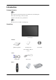
Introduction Package Contents Note Please make sure the following items are included with your LCD Display. If any items are missing, contact your dealer. Contact a local dealer to buy optional items. Note This stand is not for the Floor Standing Type.
Introduction Others Remote Control Batteries (AAA X 2) HDD Cover (Not available in all locations) Sold separately DVI Cable Wall Mount KIT LAN Cable TV tuner box Semi Stand KIT Note • You can purchase and connect a separate network box or TV tuner box. For information on how to use these, refer to their respective user manuals. • You can only connect one external box. Your LCD Display Front MENU button [MENU] Opens the on-screen menu and exits from the menu.
Introduction Moves from one menu item to another vertically or adjusts selected menu values. Adjust buttons (Left-Right buttons) / Volume buttons Moves from one menu item to another horizontally or adjusts selected menu values. When OSD is not on the screen, push the button to adjust volume. ENTER button [ENTER] Activates a highlighted menu item. SOURCE button [SOURCE] Switches from PC mode to Video mode.
Introduction POWER S/W ON [ │ ] / OFF [O] Switches the LCD Display On/Off. POWER IN The power cord plugs into the LCD Display and the wall plug. RS232C OUT/IN (RS232C Serial PORT) MDC(Multiple Display Control) Program Port DVI / PC / HDMI IN [DVI/PC/HDMI AUDIO IN] (PC/DVI/HDMI Audio Connection Terminal (Input)) DVI / PC / HDMI IN [HDMI] Connect the HDMI terminal at the back of your LCD Display to the HDMI terminal of your digital output device using a HDMI cable.
Introduction DC OUT [5V/1.5A] Connect this to the POWER connector of a TV tuner box or network box. AV IN [VIDEO] (VIDEO Connection Terminal) Connect the [ VIDEO ] terminal of your monitor to the video output terminal of the external device using a VIDEO cable.
Introduction Kensington Lock The Kensington Lock is a device used to physically fix the system when using it in a public place. The locking device has to be purchased separately. The appearance and locking method may differ from the illustration depending on the manufacturer. Refer to the manual provided with the Kensington Lock for proper use. The locking device has to be purchased separately. Note The location of the Kensington Lock may be different depending on its model.
Introduction POWER OFF Number Buttons DEL button + VOL MUTE TV/DTV MENU INFO COLOR BUTTONS TTX/MIX STILL AUTO S.MODE MDC LOCK SOURCE ENTER/PRE-CH CH/P D.MENU GUIDE RETURN Up-Down Left-Right buttons EXIT SRS MagicInfo P.MODE DUAL/MTS PIP SWAP 1. POWER Turns the product On. 2. Off Turns the product Off. 3. Number Buttons Press to change the channel.
Introduction 4. DEL button The "-" button operates only for DTV. It is used to select MMS (multi-channel) for a DTV. 5. + VOL - Adjusts the audio volume. 6. Pauses (mutes) the audio output temporarily. This is displayed on the lower left corner of the screen. The audio resumes if MUTE or - VOL + is pressed in the Mute mode. MUTE 7. TV/DTV Selects the TV and DTV mode directly. 8. MENU Opens the on-screen menu and exits from the menu or closes the adjustment menu. 9.
Introduction 24. Up-Down Left-Right buttons Moves from one menu item to another horizontally, vertically or adjusts selected menu values. 25. EXIT Exits from the menu screen. 26. SRS Selects SRS TruSurround XT mode. 27.MagicInfo MagicInfo Quick Launch Button. 28. P.MODE When you press this button, current picture mode is displayed on the lower center of the screen. AV / HDMI / TV : P.MODE The LCD Display has four automatic picture settings that are preset at the factory.
Introduction Installation VESA Bracket • When installing VESA, make sure to comply with the international VESA standards. • Purchasing VESA Bracket and Installation Information : Please contact your nearest SAMSUNG Distributor to place an order. After your order is placed, installation professionals will visit you and install the bracket. • At least 2 persons are needed in order to move the LCD Display.
Introduction Notice For securing the bracket on a wall, use only machine screws of 6 mm diameter and 8 to 12 mm length. Wall Bracket Installation • Contact a technician for installing the wall bracket. • SAMSUNG Electronics is not responsible for any damages to the product or harm to customers when the installation is done by the customer. • This product is for installing on cement walls. The product may not stay in place when installed on plaster or wood.
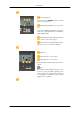
Introduction 2. A- Captive Screw B- Wall Bracket C- Hinge (Left) D- Hinge (Right) Before drilling into the wall, check if the length between the two locking holes at the back of the product is correct. If the length is too short or long, loosen all or some of the 4screws on the wall bracket to adjust the length. A- 3. Length between the two locking holes Check the installation diagram and mark the drill points on the wall. Use the 5.0 mm bit to drill holes deeper than 35 mm.
Introduction 1. Remove the 4 screws on the back of the product. 2. Insert the screw B into the plastic hanger. Notice • Mount the product on the wall bracket and make sure it is properly fixed to the left and right plastic hangers. • Be careful when installing the product on the bracket as fingers can be caught in the holes. • Make sure the wall bracket is securely fixed to the wall, or the product may not stay in place after installation. 3.
Introduction A- LCD Display B- Wall Bracket C- Wall Wall Bracket Angle Adjustment Adjust the bracket angle to -2° before installing it on the wall. 1. Fix the product to the wall bracket. 2. Hold the product at the top in the center and pull it forward (direction of the arrow) to adjust the angle. 3. You can adjust the bracket angle between -2° and 15°. Make sure to use the top center, and not the left or the right side of the product to adjust the angle.
Introduction Installation VESA Bracket • When installing VESA, make sure to comply with the international VESA standards. • Purchasing VESA Bracket and Installation Information : Please contact your nearest SAMSUNG Distributor to place an order. After your order is placed, installation professionals will visit you and install the bracket. • At least 2 persons are needed in order to move the LCD Display.
Introduction Wall Bracket Installation • Contact a technician for installing the wall bracket. • SAMSUNG Electronics is not responsible for any damages to the product or harm to customers when the installation is done by the customer. • This product is for installing on cement walls. The product may not stay in place when installed on plaster or wood. Components Only use the components and accessories shipped with the product.
Introduction 2. Before drilling into the wall, check if the length between the two locking holes at the back of the product is correct. If the length is too short or long, loosen all or some of the 4screws on the wall bracket to adjust the length. A- 3. Length between the two locking holes Check the installation diagram and mark the drill points on the wall. Use the 5.0 mm bit to drill holes deeper than 35 mm. Fix each anchor in the corresponding hole.
Introduction 2. Insert the screw B into the plastic hanger. Notice • Mount the product on the wall bracket and make sure it is properly fixed to the left and right plastic hangers. • Be careful when installing the product on the bracket as fingers can be caught in the holes. • Make sure the wall bracket is securely fixed to the wall, or the product may not stay in place after installation. 3. Tighten the 4 screws in step 2 (plastic hanger + screw B)to the rear holes of the product. 4.
Introduction A- LCD Display B- Wall Bracket C- Wall Wall Bracket Angle Adjustment Adjust the bracket angle to -2° before installing it on the wall. 1. Fix the product to the wall bracket. 2. Hold the product at the top in the center and pull it forward (direction of the arrow) to adjust the angle. 3. You can adjust the bracket angle between -2° and 15°. Make sure to use the top center, and not the left or the right side of the product to adjust the angle.
Connections Connecting a Computer Using a Power cord with Earth • In the event of failure, the earth lead may cause electric shock. Make sure to wire the earth lead in correctly, before connecting the AC power. When unwiring the earth lead, make sure to disconnect the AC power in advance. Note AV input devices such as DVD players, VCRs or camcorders as well as your computer can be connected to the LCD Display.
Connections Connect the audio cable for your LCD Display to the audio port on the back of your computer. Note • Turn on both your computer and the LCD Display. • The DVI cable is optional. • Contact a local SAMSUNG Electronics Service Center to buy optional items. Connecting to Other devices Using a Power cord with Earth • In the event of failure, the earth lead may cause electric shock. Make sure to wire the earth lead in correctly, before connecting the AC power.
Connections Connecting to a Camcorder 1. Locate the AV output jacks on the camcorder. They are usually found on the side or back of the camcorder. Connect a set of audio cables between the AUDIO OUTPUT jacks on the camcorder and the AV AUDIO IN [L-AUDIO-R] on the LCD Display . 2. Connect a video cable between the VIDEO OUTPUT jack on the camcorder and the AV IN [VIDEO] on the LCD Display . 3.
Connections Connecting Using a DVI to HDMI Cable Note • Connect the DVI output terminal of a digital output device to the HDMI terminal of the LCD Display using a DVI to HDMI cable. • Connect the red and white jacks of an RCA to stereo (for PC) cable to the same colored audio output terminals of the digital output device, and connect the opposite jack to the DVI / PC / HDMI AUDIO IN terminal of the LCD Display.
Connections Note Connect the LAN cable. Connecting a USB device Using a Power cord with Earth • In the event of failure, the earth lead may cause electric shock. Make sure to wire the earth lead in correctly, before connecting the AC power. When unwiring the earth lead, make sure to disconnect the AC power in advance. Note AV input devices such as DVD players, VCRs or camcorders as well as your computer can be connected to the LCD Display.
Troubleshooting Self-Test Feature Check Note Check the following items yourself before calling for assistance. Contact a Service Center for problems that you cannot solve by yourself. Self-Test Feature Check 1. Turn off both your computer and the LCD Display. 2. Unplug the video cable from the back of the computer. 3. Turn on the LCD Display.
Troubleshooting • Do not use benzene, thinner or other flammable substances, or a wet cloth. • We recommend that a SAMSUNG cleansing agent is used to prevent damage to the screen. 2) Maintaining the Flat Panel Display Screen. Clean with a soft cloth (cotton flannel) smoothly. • Never use acetone, benzene or thinner. (They may cause flaws or deformation of the screen surface.) • The user will be required to pay costs and related expenses for repairing damages caused.
Troubleshooting A: Check if the signal cable between the computer and the LCD Display is securely connected. (Refer to Connecting a Computer) Problems related to the Screen Note Problems related to the LCD Display screen and their solutions are listed. Q: The screen is blank and the power indicator is off. A: Ensure that the power cord is firmly connected and the LCD Display is on. (Refer to the Connecting a Computer) Q: "Check Signal Cable" message.
Troubleshooting A: Adjust color using Custom under OSD Color Adjustment menu. Q: The color image is distorted by dark shadows. A: Adjust color using Custom under OSD Color Adjustment menu. Q: The color white is poor. A: Adjust color using Custom under OSD Color Adjustment menu. Q: The Power Indicator blinks. A: The LCD Display is currently saving the changes made in the settings to the OSD memory. Q: The screen is blank and the power indicator light blinks every 0.5 or 1 seconds.
Troubleshooting A: Check if the power is on. A: Check if the power cord is securely connected. A: Check if a special fluorescent or neon lamp is on in the vicinity. Problems related to MagicInfo Note Making a Bootable USB Flash Disk. Q: Making a Bootable USB Flash Disk A: 1) You can turn a common 512-MB or bigger USB storage media into a bootable disk using a USB bootable disk creation tool.
Troubleshooting Set the resolution at the Control Panel → Display → Screen Saver. Set the function in the BIOS-SETUP of the computer. (Refer to the Windows / Computer Manual). Q: How can I clean the outer case/LCD Panel? A: Disconnect the power cord and then clean the LCD Display with a soft cloth, using either a cleaning solution or plain water. Do not leave any detergent or scratches on the case. Do not let any water enter the LCD Display.