4 CHANNEL DVR User Manual Z6806127401A_SRD-470, 470D-IB_EN1 1 SRD-470/470D 2010-04-30 오후 6:06:23
4 Channel DVR User Manual Copyright ©2009 Samsung Techwin Co., Ltd. All rights reserved. Trademark is the registered logo of Samsung Techwin Co., Ltd. The name of this product is the registered trademark of Samsung Techwin Co., Ltd. Other trademarks mentioned in this manual are the registered trademark of their respective company. Restriction Samsung Techwin Co., Ltd shall reserve the copyright of this document.
IMPORTANT SAFETY INSTRUCTIONS Read these operating instructions carefully before using the unit. Follow all the safety instructions listed below. Keep these operating instructions handy for future reference. 1) Read these instructions. 2) Keep these instructions. 3) Heed all warnings. 4) Follow all instructions. 5) Do not use this apparatus near water. 6) Clean only with dry cloth. 7) Do not block any ventilation openings, Install in accordance with the manufacturer’s instructions.
overview BEFORE START This user manual provides Information for using the DVR such as brief introduction, part names, functions, connection to other equipment, menu setup, etc. You have to keep in mind the following notices : • SAMSUNG retains the copyright on this manual. • This manual cannot be copied without SAMSUNG’s prior written approval. • We are not liable for any or all losses to the product incurred by your use of non-standard product or violation of instructions mentioned in this manual.
CONTENTS OVERVIEW 4 13 CONNECTING WITH OTHER DEVICE 17 LIVE 21 USING THE DVR 32 Before Start Features Part Names and Functions (Rear) Part Names and Functions (Front) Remote Control 13 14 Checking the installation environment HDD Addition 17 17 17 18 18 19 Connecting the Video, Audio, and Monitor Connecting the USB Connecting POS Device Connecting the Alarm Input/Output Connecting the RS485 Device Connecting the Network 21 23 27 29 29 30 30 30 Getting Started Live Screen Configuration Live Mode S
overview 66 69 Search Playback 70 70 71 73 79 83 93 Introducing Web Viewer Connecting Web Viewer Using Live Viewer Using Search Viewer Viewer Setup About BACKUP VIEWER 94 SEC Backup Viewer 96 99 100 103 Product Specification Product Overview Default Setting Troubleshooting SEARCH & PLAY 66 WEB VIEWER 94 APPENDIX 96 6_ overview Z6806127401A_SRD-470, 470D-IB_EN6 6 2010-04-30 오후 6:06:41
FEATURES The SRD DVR (Digital Video Recorder) employs H.264 video encoding for 4 channel inputs and G.723 audio encoding for 4 channels while simultaneously supports hard disc recording and playback. These DVRs also supports network connectivity, providing remote monitoring from a remote PC transferring video and audio data.
overview Standards Approvals M This equipment has been tested and found to comply with the limits for a Class A digital device, pursuant to part 15 of the FCC Rules. These limits are designed to provide reasonable protection against harmful interference when the equipment is operated in a commercial environment.
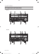
PART NAMES AND FUNCTIONS (REAR) 1 2 3 4 5 OVERVIEW 11 10 9 Part Names 8 7 6 Functions VGA Output port for VGA video signal. RS-232C RS-232C communications port. VIDEO OUT BNC type of output port for the composite video signal. AUDIO OUT Output port (RCA jack) for the audio signal. It is recommended to use an amplifier-integrated speaker for the output of the audio signal. AUDIO IN 1~4 Output ports (RCA jacks) for the audio signal. NETWORK Network connection port.
overview PART NAMES AND FUNCTIONS (FRONT) SRD-470 1 2 3 5 SRD-470 9 8 7 6 SRD-470D 1 2 3 4 5 SRD-470D 9 8 7 6 10_ overview Z6806127401A_SRD-470, 470D-IB_EN10 10 2010-04-30 오후 6:06:45
Part Names Functions Power LED : Displays the power ON/OFF status. Power Power Button : Used to turn the DVR ON/OFF. In Live mode, pressing it will switch the mode to 4-split, PIP, and Auto Sequence in sequence. In Search mode, pressing it will switch the mode to 9-split and 4-split in sequence. For the Play Screen mode, refer to “Play”. (page 69) AUDIO Sets Audio ON/OFF. ALARM Cancels the ALARM LED and the audible alarm when the alarm is going off, and to remove the icon.
overview REMOTE CONTROL SEARCH Displays the search menu. BACKUP Displays the Backup Menu. OPEN/CLOSE MODE Changes the screen mode. POWER Opens or closes the CD tray. DVR Activates the DVR function. Displays the Exit pop up screen. NUMBER [0~+10] Used as the numeric input keys, or displays a single channel. ID Skip Backward (by unit time), Slow Rewind, Slow Forward, Skip Forward (by unit time) Sets the ID of the system. Select 2 digits from 0 ~ 9 while pressing the ID Key.
installation Please take note of the followings before using this product. Do not use the product outdoor. Do not spill water or liquid in the connection part of the product. Do not impose the system to excessive shock or force. Do not pull out the power plug forcefully. Do not disassemble the product on your own. Do not exceed the rated input/output range. Use a certified power cord only. For the product with an input ground, use a grounded power plug.
installation HDD ADDITION You can install additional HDDs. Make sure to unplug the power cord from the wall outlet to prevent possible electric shock, injury or product damage. Please consult your provider for further information on HDD installation since improper installation or settings may damage the product. Number of HDDs supported : SRD-470 : Default 1 HDD + Up to 1 HDD added SRD-470D : Default 1 HDD Make sure to unplug the power cord from the wall outlet before proceeding with the installation.
1. First, loosen the screws on both sides and remove the cover. INSTALLATION 2. Loosen the left and right screws on the lower hard disk bracket to remove it. 3. Insert the additional hard disk into the bracket and fix it using the provided screws.
installation 4. Insert the bracket where the additional hard disk is inserted into the lower bracket and fix it using the provided screws. 5. When done, connect the power cable and connect the signal cable (SATA cable) to the connector for the main board. SATA2 SATA1 6. Check if the connectors are properly connected and there is no problem with wiring, and close the cover and fix it with screws.
connecting with other device CONNECTING THE VIDEO, AUDIO, AND MONITOR VIDEO IN AUDIO OUT CONNECTING WITH OTHER DEVICE VIDEO OUT(VGA) VIDEO OUT AUDIO IN MONITOR SPOT OUT CONNECTING THE USB 1. There is one USB port at the front and one at the back of the product. 2. You can connect a USB HDD, USB CD/DVD player, USB memory or mouse to the USB port. 3. If a USB HDD is connected to the system, recognition and settings are available in “Menu > Setting the Device > Storage Device”. (Page 44) 4.
connecting with other device CONNECTING THE ALARM INPUT/OUTPUT Connecting the alarm input signal Connection port for the alarm input signal. Connect one strand of the sensor signal line (two strands) to the alarm input port and connect the other to the [G] port. Connecting the alarm output signal Connection port for the alarm output signal. Connect one strand of the sensor signal line (two strands) to the alarm output port and connect the other to the [COM] port.
CONNECTING THE NETWORK Connecting to Internet through Ethernet (10/100/1000BaseT) CONNECTING WITH OTHER DEVICE RJ-45 Ethernet Cable (Direct Cable) INTERNET Back Bone Hub/Switcher Windows Network Viewer Hub/Switcher Connecting to the Internet using the router INTERNET Router xDSL or Cable Modem xDSL or Cable Modem External Remote PC DDNS Server (Data Center) English _19 Z6806127401A_SRD-470, 470D-IB_EN19 19 2010-04-30 오후 6:07:06
connecting with other device Connecting to Internet through ADSL RJ-45 Ethernet Cable (Direct Cable) INTERNET Phone(ADSL) Line Hub/Switcher ADSL MODEM Windows Network Viewer 20_ connecting with other device Z6806127401A_SRD-470, 470D-IB_EN20 20 2010-04-30 오후 6:07:08
live GETTING STARTED Starting the system LIVE 1. Connect the power cable of the DVR to the wall outlet. 2. Press the Power button on the front panel. REC 3. You will see the initialization screen. The initialization process will last about 1 minute. If a new HDD is installed, the initialization process may take longer. REC 4. The live screen appears with a beep. Shutting Down the System You can shut down the system only if you have logged in to the DVR.
live Login To access a DVR or restricted menu, you should have logged in to the DVR. 1. In live mode, right-click any area of the screen. You will see the context sensitive menu as in the right figure. Scene Mode Audio Off Freeze Stop Alarm Record Play Search Backup Main Menu Shutdown Hide Launcher Login 2. Click . The login dialog appears. You can also see the login dialog to access a desired menu by pressing the [MENU] button on the remote control or the front panel.
LIVE SCREEN CONFIGURATION Icons on the Live Screen You can check the status or operation of the DVR with the icons on the live screen. 2010-01-01 00:00:01 LIVE CAM 01 Name Description Current Date, Time Displays the current time and date. Login Information When you are logged in, the “LOG ON” icon will be displayed. Displayed if the zoom function is activated. Displayed if you press the Pause button.
live Error Information • If you turn on the system when the internal HDD is not connected or an error occurs, the “HDD FAIL” icon ) will be displayed on the top left corner. In this case, make sure you contact the service center for ( assistance as this may cause a failure of recording, playback or backup. • If the cooling fan does not work properly or has a problem, the window will appear and the fan error icon ( ) will be displayed on the top left corner.
Menu Description Refer to “Live Mode”. (Page 27) Spot Out Refer to “Spot Out”. (Page 29) Audio On/Off Refer to “Audio ON/OFF”. (Page 30) Freeze Refer to “Freeze”. (Page 30) Stop Alarm Stops the alarm output and the event monitoring. Refer to “Event Monitoring”. (Page 30) Record/Stop Starts/stops the standard recording. Play Plays the search result (data). Refer to “Search & Play > Play”. (Page 69) Search Refer to “Search & Play > Search”.
live View the Launcher Menu The Launcher menu appears on the bottom of the live screen. 1. In Live mode, right-click to display the context menu and select . 2. Move the cursor to the bottom and click a desired item in the Launcher menu. M If no input is entered for 10 seconds, the menu will disappear. The Launcher menu can be accessed only by using the mouse. PTZ Alarm Freeze Menu Description Date/Time Displays the current time and date.
LIVE MODE Displays 4 live video images in 3 different modes. Switching the screen mode CH1 CH2 LIVE To switch the split mode, select a screen mode in the launcher menu, or right-click to select a screen mode in the context menu. Press the [MODE] button on the front panel or the remote control to switch the mode in the sequence of the launcher menu items.
live Channel Setting You can display the channel in a desired area of a split screen. 1. Place the cursor over the camera name of each channel to display the <▼> key to the right on the screen. 2. Click a camera name to display a channel list where you can select a different channel. 3. Select a desired channel and click it. The current channel will be switched to the selected one.
SPOT OUT The Spot Out monitoring is independent of the Live mode, which monitors a specific channel through the Spot Out port. Selecting a Spot Out mode If an event occurs such as sensor, motion or alarm from the Spot Out port in connection with a monitor, you can select a output screen mode. LIVE 1. In Live mode, right-click any area on the screen. The Live menu appears. Scene Mode Spot Out Spot Out 1 Audio Off 2. Click Spot Out. Supports the Spot output in Single screen with Auto Sequence mode.
live AUDIO ON/OFF You can turn the sound on/off corresponding to the channel in Live mode. AUDIO ON/OFF in Single mode Click the audio icon ( to turn it on/off. M ) on the screen, or press the [AUDIO] button on the front panel or the remote control Only the channel where
Ex : If you set to 5 seconds, and the second event occurs in CH 2 within the set time after the first event occurred in CH 1. Event occurrence 4 seconds 9 seconds Stop alarm LIVE CH1 CH2 CH1 M Press the [ALARM] button to reset the alarm settings and to release the event mode. If an alarm activates in the condition you have set the event record, and pre/post alarm times, the event record will be performed.
using the DVR You can setup the system properties, devices, and options for recording, event, backup and network. SYSTEM SETUP You can setup Date/Time/Language, Permission, System Properties and Log. Date/Time/Language You can check and setup the current Date/Time and time related properties, as well as the language used for the interface on the screen. Setting the Date/Time/Language Set the Date/Time/Language Using the mouse may help make setup easier. 1.
- Time Server : Enter an IP or URL address of the time Date/Time/Language server. Date/Time/Language Holiday - Last Sync Time : Displays the most recent Time Synchronization Setup synchronization time from the selected time server. - Activate as Server : Set to
using the DVR Permission Management You can set permissions of each user over the DVR's specific function and settings. Setting the Administrator You can set and change Administrator’s ID and password. The administrator can use and set all menu items and functions. Using the mouse may help make setup easier. 3. Use the up/down buttons ( ) in window to move to , and press [ENTER] button. 4. Select . A dialog for Admin ID and Password input appears.
Setting the Group You can create user groups and setup permissions for those user groups. You can register a user for each group in . Using the mouse may help make setup easier. 3. Use the up/down buttons ( ) in window to move to , and press [ENTER] button. 5. Use direction buttons ( item, and set the value. Group Admin User x Group Add Setup Delete Rename Group Authority Live View Setup Search Setup USING THE DVR 4. Select .
using the DVR To restrict the user permissions If the admin restricts all permissions of an added group, the users belonging to that group can access only the default minimum menus and can change the user’s own password only. 1. Start the DVR. If all permissions are restricted, only the Login dialog should appear. 2. Log in with a registered user ID. Login x ID abc x Password OK Cancel 3. Right-click any area on the screen.
Setting the User Users can be added only if a group was created in menu. Using the mouse may help make setup easier. 3. Use the up/down buttons ( ) in window to move to , and press [ENTER] button. 5. Use direction buttons ( ◄ ►) to select from the window. A window for “Add User” appears. You can configure the Network Viewer settings including name, ID, viewer, Select Group and password. Result of the user setup appears in the window.
using the DVR • Manual Input of ID : Prompts you to enter the user ID manually for the login process. - Checked ( ) : Encloses the registered user IDs with the [½] symbols. Use the virtual keyboard to enter the user ID. Login x ID ***** x Password 6. When the permission setup is done, press . OK Cancel System Management You can check the system version, update to a newer version, as well as data backup and initialization.
• Updating the Software 1. Connect a device storing the software to be updated. (It may take about 10 seconds to recognize the device.) Upgradeable devices include USB memory, CD/DVD and network device. To update the network, the current DVR should have been Settings System Information x Software Version System Format x Broadcast V1.00h_100315180929 Upgrade NTSC x MAC Address Current Version 00:00:F0:54:FF:FF V1.00h_100315180929 New Version V1.
using the DVR Settings You can copy and import the DVR settings by using a storage media. Using the mouse may help make setup easier. 3. Use the up/down buttons ( ) in window to move to , and press [ENTER] button. System Management Settings System Information x Storage Device 4. Select . A window of storage device and load factory default appears.
Event Log Event log shows recorded events on alarms, motion detections and video loss. It also shows the log and its timestamp. Using the mouse may help make setup easier. 3. Use the up/down buttons ( ) in window to move to , and press [ENTER] button. 4. Select . System Log Search Day First Page ◄ ►) to move to the desired 6. Set Search Day, Channel and Type and the press . Event Log Last Page CH All CHs Type View all No.
using the DVR SETTING THE DEVICE You can setup Camera, Storage Device, Remote Device, POS Device and Monitor. Camera Setting the Camera You can set Video, Audio, Channel Name and Dwell Time of a Camera. Using the mouse may help make setup easier. 1. Press the [MENU] button on the remote control or front panel. Logout 2. Use the left/right button (◄ ►) to select . Device setting menu is selected. 3. Use the up/down buttons ( and press [ENTER] button.
• Progressive : You can set the progressive camera to ON/OFF. J If you set it to for the progressive camera, screen flickering will be reduced. • Screen Setup : The video appeared on the screen may vary depending on the channel’s camera, configure the DVR display to your preferences. Select a channel and adjust the < (Brightness)>, < (Contrast)>, and < (Color)> of the selected channel. 6. When the camera setup is done, press .
using the DVR Storage Device You can check information on storage devices. Confirming Devices You can check storage devices and their free space, usage as well as status. Devices available are HDD, and USB devices (Memory, HDD, CD/DVD). Refer to “Product Specifications > Backup”. (Page 96) Using the mouse may help make setup easier. 3. Use the up/down buttons ( ) in window to move to , and press [ENTER] button. 4. Select .
Formatting You can format a storage device. Using the mouse may help make setup easier. 3. Use the up/down buttons ( ) in window to move to , and press [ENTER] button. 4. Select . A window for selection of device for formatting appears. Format Device HDD Alarm Device Select Used/Total Usage HDD 1 12.28G/499.37G Internal ◄ ►) to select a device to be USING THE DVR 5. Use direction buttons ( formatted. Storage Device Format OK 6.
using the DVR • Duration : Sets the alarm duration for the alarm signal and beep sound. - If was selected, a beep will sound. - If was selected, both beep sound and alarm signal through rear side ports will output. M status means that the HDD is operating but it has problems that require technical examination. ( ) appears on the Live screen. status means that the HDD has defect and requires immediate replacement. ( ) appears on the Live screen. 6.
• POS Device Setup : Sets the communication setups for the POS device and DVR. It is independent to the Remote Device setup. POS Device POS USE POS Device Setup POS CH 1 None Preset 2 NoneSetup POS Device 3 4 If selected a channel input field, “Sync Channel Setup” window appears. One POS device can be synchronized to up to 4 cameras 9600 None Parity None name, start string, and end string. • Port/Ethernet : Sets the port number for the DVR and POS device connection.
using the DVR Monitor You can configure information to be displayed and its format for Spot Out monitor. Setting the Monitor Using the mouse may help make setup easier. 3. Use the up/down buttons ( ) in window to move to , and press [ENTER] button. 4. Select . Monitor Monitor x Event Display Spot Out Mode OFF x Display Date Time CH Name Icon ◄ ►) to move to a desired 5. Use direction buttons ( item, and set the value.
Setting the Spot Out You can set the DVR to output information / video apart from the monitor out. Using the mouse may help make setup easier. 3. Use the up/down buttons ( ) in window to move to , and press [ENTER] button. 4. Select . Monitor Spot Out Monitor x Spot Out 1 Mode All Set Mode SEQ The number of Spot Out terminals differs according to the 5. Use direction buttons ( item, and set the value.
using the DVR SETTING THE RECORDING You can setup scheduled recording, event recording and other recording related settings. Recording Schedule Make your reservation on a date and time to schedule the recording on specified time. Using the mouse may help make setup easier. 1. Press the [MENU] button on the remote control or front panel. Logout 2. Use the left/right button (◄ ►) to select . Record menu is selected. Exit Record ) to move to
Recording Color Tags Color Function White No Recording Orange Continuous Blue Event Green Both(Cont&Evnt) Description No schedule / event recording Scheduled recording only Event recording only Both scheduled / event recordings USING THE DVR Each press of a selected cell will cycle through --. Event Record Duration You can set the beginning and ending point of a recording on an event. Using the mouse may help make setup easier. 3.
using the DVR Setting Event Recording Properties You can set each channel’s resolution, quality and IPS for event recordings. Using the mouse may help make setup easier. 3. Use the up/down buttons ( ) in window to move to , and press [ENTER] button. REC Quality & Resolution Event Standard CH 4. Select . Event recording setup window appears.
• Auto Delete : If you check it, Record Period setup is activated. If you setup the auto delete, recorded data only in the configured period are searchable. 5. When the recording option setup is done, press . SETTING THE EVENT You can set recording options for sensor, motion, and video loss event. You can set the sensor’s operating condition and connected camera, as well as alarm output and its duration. Using the mouse may help make setup easier. 1.
using the DVR • Alarm : Sets the alarm output method. For further information on alarm output, refer to “HDD Alarm > Alarm”. (Page 45) • Duration : Sets the duration of alarm signal and alarm sound. Sensor Detection Sensor Sensor Operation Cam 1 OFF 1 None 10 sec 2 OFF 2 None 10 sec 3 None 4 None 3 Alarm OFF Setup 4 OFF 1 Alarm 2 Duration 10 sec 10 sec BEEP All OK 5. When the sensor detection setup is done, press .
Video Loss Detection You can set the alarm to be generated on a camera disconnection, which causes a video loss. Using the mouse may help make setup easier. 3. Use the up/down buttons ( ) in window to move to
using the DVR BACKUP You can check the backup device and set the backup schedule by channel or by time. The product only supports external HDD of USB memory/DVD and USB type. (Page 96) Setting the Backup You can backup the desired data to a connected device. Using the mouse may help make setup easier. 1. Press the [MENU] button on the remote control or front panel. Logout 2. Use the left/right button (◄ ►) to select . Backup menu is selected. Exit Backup Backup 3. Press the [ENTER] button.
5. When the backup setup is done, press . If no available device is recognized for backup, button is not activated. J The application may slow down during the backup. You can switch to the menu screen during the backup in operation, but playback of data is not available. When a CD/DVD or memory device is used for backup, it is not available to use the full capacity of the media since the system consumes a part of its capacity. will fail.
using the DVR • IP, Gateway, Subnet Mask, and DNS - For : You can directly input IP address, Gateway, Subnet Mask and DNS. - For : IP address, Gateway, and Subnet Mask are set automatically. - For : IP address, Gateway, and Subnet Mask are set automatically. • User ID, Password : In case you selected ADSL, provide the “User ID” and its “Password”. M Connection Mode Connection Protocol x Connection Mode ADSL x Bandwidth 600kbps x IP 192.168. 1.200 x Gateway 192.168.
DDNS You can set the DDNS site for a remote user’s network connection. Using the mouse may help make setup easier. 3. Use the up/down buttons ( ) in window to move to , and press [ENTER] button. 4. Use virtual keyboard to enter user inputs. Refer to “Using Virtual Keyboard”. (Page 34) DDNS x DDNS Site OFF x Host Name x User Name x User Password ******** USING THE DVR If selected or , input fields are deactivated. 5. When the DDNS setup is done, press .
using the DVR When a router is used J To avoid IP address conflict with the DVR's static IP, check followings : • Setting the DVR with a static IP - Internet connection : You can connect the DVR to a router which is connected to an ADSL/Cable modem or a router in a Local Area Network (LAN) environment. • Setting the DVR Network 1. Set the in menu of the connected DVR to . 2. Check whether the set IP address is in the static IP range provided by the IP router.
DDNS Setting DDNS is a short form of Dynamic Domain Naming System. DNS (Domain Name System) is a service that routes a domain name consisting of user friendly characters (ex : www.google.com) to an IP address consisting of numbers (64.233.189.104). DDNS (Dynamic DNS) is a service that registers a domain name and the floating IP address with the DDNS server so that the domain name can be routed to the IP address even if the IP is changed in a dynamic IP system.
using the DVR Mailing Service You can send an e-mail to a DVR-registered user at a specific time interval, or if an event occurs. M If an event occurs with a channel where the camera’s video is set to or the remaining recording count is set to , only the text notification will be sent to the applicable email address. SMTP Setting Sets the SMTP mail server. Using the mouse may help make setup easier. 3.
Group Setting You can set the group to whom the e-mail is sent, and specify the permission for each group. You can add recipients for each group in the menu item. The recipient is set separately from the DVR user group. Using the mouse may help make setup easier. 3. In the setting window, press the up/down ( ) button to move to and press the [ENTER] button.
using the DVR CONTROLLING A PTZ DEVICE The DVR enables you to adjust the settings of a PTZ camera as well as an ordinary one to your preference. PTZ Device The PTZ device can be activated only if a channel in connection with the PTZ camera is selected. Getting started with PTZ The PTZ camera is available, only if a channel is selected, in the following way : Using the button on the remote control or the front panel Scene Mode Select the [PTZ] button on the remote control or the front panel.
• Focus : Enables you to adjust the focus manually. • Auto Pan : The camera automatically runs between the two points that you selected. • Scan : The camera moves to the preset points in the specified sequence. If multiple presets are specified, the PTZ camera will automatically move to all of the preset points one at a time. • Pattern : Makes the PTZ camera remember and follow the past route.
search & play SEARCH You can perform the search for recorded data by the time or by the search criteria such as an event. You can access the menu directly in Live mode. 1. In Live mode, right-click any area of the screen. The Live menu appears. Scene Mode Spot Out Audio Off 2. Select . Or, press the [SEARCH] button on the remote control or the front panel. Freeze Stop Alarm Record Play Search Backup Main Menu Shutdown Hide Launcher Logout 3. The Search menu appears.
• Zoom In : The map enlarges in detail. It will switch in the sequence of 24 hours - 4 hours - 1 hour - 5 minutes. • Zoom Out : The map will switch in the reverse order of the detailed mode above. It will switch in the sequence of 5 minutes - 1 hour - 4 hours - 24 hours. M Time Search Go to First 2010-01-01 Go to Last Overlapped Data List1 Zoom In Zoom Out 00:01 All Data CAM 01 CAM 02 CAM 03 2010/01/01 00:01:17 CAM 04 Standard Schedule Motion Sensor V.
search & play POS Search You can search for data in the POS device that is connected to the DVR. You can use the mouse to select the related items. 4. Select in the menu. ◄ ►) to set the search criteria 5. Use direction buttons ( and press the [ENTER] button. You can enter specific text to refine your search. • Keyword : Use the virtual keyboard to enter a keyword. • Search Criteria : - : If selected, search will be performed case-sensitively.
PLAYBACK Play You can play data stored in the HDD and backup a desired portion of the data. Using the mouse may help make setup easier. 1. In Live mode, click in the right-click menu or < > in the launcher menu, or press the Play button on the remote control or the front panel. Audio Off SEARCH & PLAY 2. Use the up/down button ( Scene Mode Spot Out Freeze Stop Alarm ) to select a menu. Record Play For data search, refer to .
web viewer INTRODUCING WEB VIEWER What is Web Viewer? Web Viewer allows remote access to your DVRs. You have access to live video, archived video, PTZ control (if configured), etc. PRODUCT FEATURES • Remote access from a standard browser • Supports PTZ camera controls • Supports 1, 4 camera viewing formats (maximum of 4 cameras in the list). • Gets JPEG, BMP format images to print and save to “Print or Save JPEG, BMP format images”. • Record video in AVI format-compatible with popular media players.
CONNECTING WEB VIEWER 1. Open your web browser and type the IP address or URL of DVR into the URL address box. M The basic URL of the DVR is as following in case of MAC address : 00-00-F0-ab-cd-ef : nabcdef.websamsung.net WEB VIEWER 00-16-6c-ab-cd-ef : mabcdef.websamsung.net 00-68-36-ab-cd-ef : pabcdef.websamsung.net You can also use registered URL which setups up in the Setup menu of your DVR. 2. Set the Admin ID and password same to those of the DVR Admin.
web viewer 6. You may have “Windows Security Alert” that attempts to block this with the Windows Firewall. In that case, click to start Web Viewer. 7. Installation is complete. Now you can see the main screen of Live Viewer.
USING LIVE VIEWER WEB VIEWER The Live Viewer screen consists of following : This displays the IP address and the model name of the connected DVR. These menus consist of , , , . These buttons are used for the screen split and full screen mode. Shows the IP address and model name of the connected DVR. Select or for the OSD time information display setting of the Live Viewer. These buttons are used for sequence and changing the screen channel.
web viewer OSD INFORMATION DISPLAY The channel number, video size, and IP address of the connected DVR are displayed. The current date and time will be displayed according to the selected time information display setting or . Alarm icon appears when alarm is issued. It disappears when pressed the [ALARM] button of the DVR. Motion icon appears when motion is detected. It disappears when pressed the [ALARM] button of the DVR. It displays whether the PTZ controls are active.
CONNECTED DVR This displays the IP address and the status of the connecting DVR. M Connection failure message No Response : Appears when the DVR does not respond. Access Denied : Appears when the maximum number of users is exceeded. The number of simultaneous connections are limited to 10. WEB VIEWER Setting the display of the OSD time information Select or for the OSD time information display setting.
web viewer SAVING THE LIVE SCREEN ON THE PC • CAPTURE : Saves the current screen into a BMP or JPEG file. M The default saving path is “C:\Program Files\Samsung\Dvr Web Viewer\SnapShot\Live”. To change the saving path, click )> button and then select the path you
CHANGING THE LIVE SCREEN CHANNEL • Blue numbers : Indicates that the current channel is connected to a camera. • Gray numbers : Indicates that the current channel is not connected to any camera. If you select 4-split mode, the channel button for each of cameras 1 ~ 4 will turn blue. WEB VIEWER USING PTZ CAMERA Click the direction buttons to control the camera. •< > You can zoom in or out an image by using the ZOOM button. •< > You can adjust the entering light amount by using the IRIS button.
web viewer • PRESET : Moves the lens direction to a preset direction. 1. If you click a preset, the camera moves to the selected preset's position. 2. You can delete the selected preset or all presets. 3. You can save a new preset number and name. M You can save presets up to 20. • AUTOPAN : Moves the camera lens direction between 2 points set for the camera. • SCAN : Moves the camera lens direction between 2 preset points of the camera.
USING SEARCH VIEWER WEB VIEWER The Search Viewer screen consists of following : This displays the IP address and the model name of the connected DVR. There are 4 tabs available: , , , . Switch to a split mode. Shows the IP address and model name of the connected DVR. These buttons are used for capture, print, and save the image. This displays a calendar at which you can search the recorded video. This displays a timeline at which you can search the recorded video by the time.
web viewer SPLIT-SCREEN You can change the split mode by clicking each number icon. SINGLE MODE QUAD MODE • Click < > button. The screen displays the selected camera connected to the DVR in “SINGLE MODE”. • Click < > button. The screen displays the selected camera connected to the DVR in “QUAD MODE”. CONNECTED DVR This displays the IP address and the status of the connecting DVR. M Connection failure message No Response : Appears when the DVR does not respond.
SAVING THE LIVE SCREEN ON THE PC • CAPTURE : Saves the current screen into a BMP or JPEG file. M The default saving path is “C:\Program Files\Samsung\Dvr • PRINT : Prints the playback screen that is now being displayed. It also prints IP address, time, camera number, and current event state. WEB VIEWER Web Viewer\SnapShot\Search”. To change the saving path, click button and then select the path you want.
web viewer SEARCHING THE RECORDED VIDEO IN THE CALENDAR If the video data has been recorded on a date, the date is distinguished in green. If you click the date, the recorded video information is displayed in the time line. When you click , it is changed to today’s date. SEARCHING THE RECORDED VIDEO IN THE TIMELINE It displays the recorded video data status on the DVR after a date is selected.
CONTROLLING PLAYBACK WEB VIEWER Fast Backward : Reverse-plays faster(2x). Reverse Play : Performs Reverse Play. Play : Performs playback. Fast Forward : Plays faster(2x). Go to First : Moves the beginning time of recorded video in the time line. Step Backward : Performs one step reverseplay by one frame. Stop : Stops playing. Step Forward : Performs one step forward by one frame. Go to Last : Moves the last time of recorded video in the time line.
web viewer • Time Synchronization Setup Set the time synchronization. • Display Date Format : Set the date type. Time : Select a time format to display on the screen. • DST (Daylight Saving Time) DST is displayed an hour ahead of the standard time of the time zone. • Language Select a preferred language for the DVR. Holiday You can set specific dates to Holidays according to your preferences. For more information, refer to in the menu.
• Group Users are classified into groups and the permission can be set according to the group. First of all, add a group. WEB VIEWER • User You can add, change or remove a user or users. • Setup You can set the user permission. System Management For more information, refer to in the menu. (Page 38) • System Information You can see information of the current system. Check the software version, broadcast format and MAC address.
web viewer Device You can check a list of devices that are connected to the DVR and configure the necessary settings. Click in the menu screen. For more information, refer to “Setting the Device”. (Page 42) Camera • Camera You can configure the settings of the camera that is connected to the DVR. • PTZ You can configure the settings of the PTZ camera that is connected to the DVR. Set the ID and protocol. Storage Device You can check and change the settings of the storage device.
• HDD Alarm You can set the alarm output channel and the alarm duration for an error. WEB VIEWER Remote Device You can see a list of remote devices including PTZ cameras and system keyboards that are connected to the RS-485 port of the DVR and configure the necessary settings. POS Device You can set the channel, preset and communication port of the POS device that is connected to the DVR. M You cannot set to use the POS device remotely.
web viewer • Spot Out With the monitor connected via the SPOT port, if there occurs an event such as Sensor, Motion, or Alarm, you can select a video output mode for external monitoring. • Mode You can switch between live mode and play mode. Record For more information, refer to . (Page 50) Recording Schedule If you set a recording schedule for a specific date and time, the recording will start at that specific time.
Event Record Duration You can set the start and end times of recording that will be activated if an event occurs. WEB VIEWER REC Quality & Resolution • Standard/Event You can set the resolution, frame rate and recording quality for each channel. Record Option You can set the Disk End Mode. Event For more information, refer to . (Page 53) Sensor Detection You can set the sensor operation mode and the synchronized camera as well as the alarm output type and the duration.
web viewer Motion Detection You can set the motion detection mode and the sensitivity as well as the alarm output type and the duration. • Motion Region Set the target motion detection area Video Loss Detection You can set the alarm output time if a video loss occurs. Alarm Schedule You can schedule the alarm output according to the day of the week and the time. The default setting is Event Sync, which activates the alarm only if an event occurs.
Network For more information, refer to . (Page 57) Connection A remote user can access the DVR via the network to check the current mode and the IP address. • Connection WEB VIEWER You can set the network connection route. • Protocol You can configure the protocol related settings. DDNS You can check the DDNS settings. Live Transfer A remote user can set the images of the DVR. • Live Transfer A remote user can set the image resolution of the transferred data.
web viewer Mailing Service You can specify the SMTP server that sends a mail if an event occurs and set the recipient group and users. • SMTP You can set the server that sends mails and specify if you use the authentication process. • Event You can set the event interval and specify which events the server sends mails for. • Group You can add a group to receive the mail if an event occurs and set the permission to receive the event mail for each group.
ABOUT Click . Displays the model name of connected DVR and the version of Web Viewer.
backup viewer SEC BACKUP VIEWER You can play a file that is backed up in the format of SEC. Backup in the format of SEC will involve in generating two files: one for the backup data and one for the viewer. If you run the backup file viewer, the backup data file will be automatically played. Recommended System Requirements PCs with a lower specification than the recommended below may not fully support forward/backward and high-speed playback.
Name Description / A toggle button. Each time you press this button, the audio output will toggle between activated and deactivated. Audio You can adjust the volume level from 0 to 100. Screen Printout Prints out the current screen. You should have installed the appropriate printer driver before you can print out the screen. File Tamper Detection / A toggle button. Each time you press this button, it will toggle between activated and deactivated.
appendix PRODUCT SPECIFICATION Item Details Operating System Embedded OS Broadcast Format NTSC/PAL System Input Voltage AC 100~240V Power Consumption 59W Video In Video Composite 4 Channel - 1.
Item Video : H.264 Audio : G.723 Resolution & Quality Resolution CIF(S) 352X240(NTSC) /352X288(PAL) 2CIF(M) 704x240(NTSC) /704x288(PAL) 4CIF(L) 704x480(NTSC) /704x576(PAL) Spec. (Quality) Level8 (high) ~ Level1 (low) Level8 (high) ~ Level1 (low) Record Mode Frame Rate NTSC : 0.9, 1.9, 3.8, 7.5, 15, 30ips PAL : 0.8, 1.6, 3.1, 6.2, 12.5, 25ips Search Mode Play If you want to add an internal HDD, please refer to “Adding a HDD”.
appendix Item Details Display Mode Single /4-splits Play Mode Play, Pause, Stop, 2xDigital Zoom Fast Forward/Fast Reverse - 2x, 4x, 8x,16x, 32x, 64x Play Backup USB External HDD USB CD/DVD Writer, Internal DVD(SRD-470D only) USB Memory USB HDD-MAX 1(USB hub not supported) Network Ethernet : 10/100/1000 BaseT, ADSL(PPPoE), DHCP Serial Communication RS-485 PTZ Device Control Remote Control Device RS-232C POS Alarm Input : 4 channels Remote Viewer PC Requirements CPU : Intel Core 2 Quad 2.
PRODUCT OVERVIEW • SRD-470/470D 353 12 APPENDIX 10.5 215 215 10.
appendix DEFAULT SETTING This returns the factory default settings. The settings are made as follows; • Use System/Load Factory Default in MENU The default settings are based on SRD-470D.
Category Details Factory Default POS Device OFF Monitor Device Spot Out Mode OFF Display All VGA 800x600 Sharpness Level1 (Low) Display Position Setup 30 Spot Out 1 CH1 ~ CH4 Live Mode ALL Play Mode ALL Recording Schedule Channel 1 Event Event Record Duration PRE Event OFF POST Event Normal Recording REC Quality/ Resolution Event Record Option Disk End Mode 1 min Resolution CIF(S) Frame Rate 7.
appendix Category Details Factory Default Connection Mode Connection Connection Mode Protocol Network DDNS Live Transfer Static IP Bandwidth 2Mbps IP 192.168.1.200 Gateway 192.168.1.1 Subnet Mask 255.255.255.0 DNS 168.126.63.
TROUBLESHOOTING Symptom Countermeasures y Check if the power supply system is properly connected. y Check the system for the input voltage from the power source. y If the problem persists even after you have taken the above actions, check the power supplier and replace it with a new one if neccessary. Some channels display just a black screen even if they receive video sources. y Check if the camera connected to the system properly displays the image.
appendix Symptom Countermeasures I've found that the DVR does not recognize as many disks as installed when I have connected multiple external HDDs to the DVR. y It takes time for the DVR to recognize multiple external HDDs. Try again in a moment and if the problem (of failure to recognize as many HDDs as connected) persists, it may occur due to a mechanical error of the HDD installed. Try again with a different HDD. A message of “Need to reset date/time.” Is displayed on the screen.
Symptom Countermeasures y If your player does not display a Live image at all, that indicates recording does not work so first check if you see an image on the screen. y Recording does not work if the recording settings are not properly configured. 1) Manual Record: Press the [REC] button on the front panel of the DVR or on the remote control to start recording. 2) Scheduled Record: Specify a desired time in Menu – Record Recording Schedule. Recording will start at the specified time.
Z6806127401A_SRD-470, 470D-IB_EN106 106 2010-04-30 오후 6:11:52
Correct Disposal of This Product (Waste Electrical & Electronic Equipment) (Applicable in the European Union and other European countries with separate collection systems) This marking on the product, accessories or literature indicates that the product and its electronic accessories (e.g. charger, headset, USB cable) should not be disposed of with other household waste at the end of their working life.
SALES NETWORK SAMSUNG TECHWIN CO., LTD. Samsungtechwin R&D Center, 701, Sampyeong-dong, Bundang-gu, Seongnam-si, Gyeonggi-do, Korea, 463-400 TEL : +82-70-7147-8740~60 FAX : +82-31-8018-3745 SAMSUNG TECHWIN AMERICA Inc. 1480 Charles Willard St, Carson, CA 90746, UNITED STATES Tol Free : +1-877-213-1222 FAX : +1-310-632-2195 www.samsungcctvusa.com SAMSUNG TECHWIN EUROPE LTD.