Indoor Unit Outdoor Unit AS07A5(A6)MA AS09A5(A6)MA AS12A5(A6)MC AS18A5(A6)RC AS24A1(A2)RC US07A5(A6)MA US09A5(A6)MA US12A5(A6)MC US18A5(A6)RC US24A1(A2)RC DUCTLESS MINI - SPLIT (Cool) ENDIDURA - MINI ENDÓCRINO (Refrigeración) SANS CONDUIT MINI - SÉPARÉ (Refroidissement) E S F DB68-01822A(3) ENGLISH ESPAÑOL FRANÇAIS OWNER’S INSTRUCTIONS & INSTALLATION MANUAL MANUAL DE INSTRUCCIONES & MANUAL DE INSTALACIÓN MANUEL D’UTILISATION & MANUEL D’INSTALLATION
Safety Precautions The following safety precautions must be taken when using your air conditioner. 1 Make sure that the indoor unit is correctly ventilated at all times; do NOT place clothing or other materials over it. 2 NEVER spill liquid of any kind into the indoor unit. Should this happen, switch off the breaker used for your air conditioner and contact your installation specialist. 3 Do NOT insert anything between the air flow blades, as the inner fan may be damaged and you may be hurt.
ENGLISH Contents ◆ PREPARING YOUR AIR CONDITIONER ■ Safety Precautions . . . . . . . . . . . . . . . . . . . . . . . . . . . . . . . . . . ■ View of the Unit . . . . . . . . . . . . . . . . . . . . . . . . . . . . . . . . . . . . . ■ Remote Control-Buttons and Display . . . . . . . . . . . . . . . . . . . . ■ Getting Started . . . . . . . . . . . . . . . . . . . . . . . . . . . . . . . . . . . . . ■ Inserting the Remote Control Batteries . . . . . . . . . . . . . . . . . . .
View of the Unit The design and shape are subject to change according to the model. Indoor Unit Air filter (under the grille) Air flow blades (outlet) Air Inlet Timer indicator Remote Control Sensor STANDARD indicator SAVING indicator SILENCE indicator NATURE indicator POWER indicator On/Off & 5 Way selection button Note E-4 ◆ For details on the 5 Way, refer to page 9.
ENGLISH Outdoor Unit Air Inlet(Rear) US07A5(A6)MA US09A5(A6)MA Air Outlet Connection Valve Outdoor Unit Air Inlet(Rear) US12A5(A6)MC Air Outlet Connection Valve (Inside) Outdoor Unit Air Inlet(Rear) US18A5(A6)RC US24A1(A2)RC Air Outlet Connection Valve E-5
Remote Control - Buttons and Display Remote control transmission indicator Operating mode ( AUTO, COOL, DRY, FAN) Temperature setting Turbo mode Sleep mode Fan speed Mode selection button (AUTO, COOL, DRY, FAN) Temperature adjustment buttons Turbo/Sleep mode selection button Air flow direction Fan speed adjustment button Swing button On Timer setting On Timer button Off Timer setting Off Timer button Battery discharge indicator 5 Way selection button E-6 On/Off & Timer Set/Cancel button
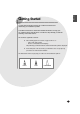
ENGLISH Getting Started You have just purchased a split type air conditioner and it has been installed by your installation specialist. Your Owner’s Instructions contain much valuable information on using your air conditioner. Please take the time to read them as they will help you take full advantage of the unit’s features. The booklet is organized as follows.
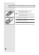
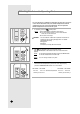
Inserting the Remote Control Batteries You must insert or replace the remote control batteries when : ◆ You purchase the air conditioner ◆ The remote control does not work correctly Note E-8 ◆ ◆ ◆ ◆ Use two AAA, LR03 1.5V batteries. Do not use old batteries or different kinds of batteries together. Batteries may be completely discharged after 12 months, even if they have not actually been used.
ENGLISH 5 Way Function You can select the 5 Way function with operating mode of the air conditioner for more comfortable circumstances. You can use the 5 Way function with the indoor unit as well as the remote control. Thus, you can use this function even though you have lost your remote control. Using with the indoor unit 1 Press the selected. (ON/OFF) button one or more times until the desired mode is To obtain a(n)... Then select...
Selecting the Automatic Operating Mode You can start the air conditioner in Automatic mode from your remote control. In the Automatic mode, the standard temperature and the optimum fan speed is selected automatically. You can adjust the standard temperature but not the fan speed. 1 If necessary, press the Result: IMPORTANT (On/Off) button. ◆ The 5 Way indicator on the indoor unit comes on. ◆ The air conditioner starts up in the mode selected when the unit was last used. ◆ The indoor unit beeps.
ENGLISH Cooling Your Room You must select the Cool mode if you wish to adjust the: ◆ Cooling temperature ◆ Fan speed when cooling 1 If necessary, press the Result: IMPORTANT (On/Off) button. ◆ The 5 Way indicator on the indoor unit comes on. ◆ The air conditioner starts up in the mode selected when the unit was last used. ◆ The indoor unit beeps.
Changing the Room Temperature Quickly The Turbo cooling function is used to cool your room as quickly as possible. Example : You have just come home and find that the room is very hot. You wish to cool it down as quickly as possible. The Turbo function operates for 30 minutes with the maximum settings before returning automatically to the mode and temperature previously selected. 1 If necessary, press the Result: 2 Press the Result: 3 E-12 ◆ The 5 Way indicator on the indoor unit comes on.
ENGLISH Removing Excess Humidity If the atmosphere in your room is very humid or damp, you can remove excess humidity without lowering the room temperature too much. 1 If necessary, press the Result: ◆ The 5 Way indicator on the indoor unit comes on. ◆ The air conditioner starts up in the mode selected when the unit was last used. ◆ The indoor unit beeps. IMPORTANT 2 (On/Off) button.
Airing Your Room If the atmosphere in your room is stale, you can air the room using the Fan feature. 1 If necessary, press the Result: 2 If the is not displayed at the top of the remote control, press the MODE button on the remote control one or more times until it appears. Result: Note 3 (On/Off) button. ◆ The 5 Way indicator on the indoor unit comes on. ◆ The air conditioner starts up in the mode selected when the unit was last used. ◆ The indoor unit beeps.
ENGLISH Adjusting the Air Flow Direction Vertically Depending on the position of the indoor unit on the wall of your room, you can adjust the position of the outer air flow blade on the bottom of the unit, thus increasing the efficiency of the air conditioner. 1 Press the SWING button one or more times as required. Result: The outer blade is adjusted vertically. RECOMMENDATION 2 Adjust the blade to face... Cooling Upwards.
Setting the On Timer The On Timer enables you to switch on the air conditioner automatically after a given period of time. You can set the period of time from 30 minutes to 24 hours. 1 To set the operating time, press the ON TIMER button one or more times until the required time is displayed. Possible time is between 0.5 hour and 24 hour inclusive. Result: 2 Press the ◆ Each time you press ON TIMER button: - The time is adjusted by 0.5 hour to 5 hours, by 1 hour from 6 hours to 24 hours.
ENGLISH Setting the Off Timer The Off Timer enables you to switch off the air conditioner automatically after a given period of time. You can set the period of time from 30 minutes to 24 hours. 1 To set the operating time, press the OFF TIMER button one or more times until the required time is displayed. Possible time is between 0.5 hour and 24 hour inclusive. Result: 2 ◆ Each time you press OFF TIMER button: - The time is adjusted by 0.5 hour to 5 hours, by 1 hour from 6 hours to 24 hours.
Setting the Sleep Timer The Sleep Timer can be used when you are cooling your room to switch the air conditioner off automatically after a period of six hours. Note If you wish to switch the unit off at a specific time, refer to page 17. 1 Make sure that you have selected either COOL mode. 2 Press the button one or more times until remote control. ◆ The indoor unit beeps. ◆ The air conditioner will be controlled as indicated in the illustrations below.
ENGLISH Operating Recommendations Here are a few recommendations that you should follow when using your air conditioner. Topic Recommendation Power failure If a power failure occurs when the air conditioner is operating, the unit is switched off. When the power returns, Note ✴✴A1✴✴ ✴✴A5✴✴ you must press the button to restart it. ✴✴A2✴✴ ✴✴A6✴✴ the air conditioner starts up again automatically (ON/OFF) Make sure which model you purchased because some air conditioners do not restart automatically.
Temperature and Humidity Ranges The following table indicates the temperature and humidity ranges within which the air conditioner can be used. If the air conditioner is used at... Then... High temperatures The automatic protection feature may be triggered and the air conditioner stopped. Low temperatures A water leakage or some other malfunction may happen if the heat exchanger freezes.
ENGLISH Cleaning Your Air Conditioner To get the best possible use out of your air conditioner, you must clean it regularly to remove the dust that accumulates on the air filter. IMPORTANT Before cleaning your air conditioner, ensure that you have switched off the breaker used for the unit. Model : AS07A5(A6)MA / AS09A5(A6)MA / AS12A5(A6)MC 1 Open the front grille by lifting the tabs on the lower right and left sides of the indoor unit. 2 Disassemble the front grille by pulling it forwards.
Solving Common Problems Before contacting the after-sales service, perform the following simple checks. They may save you the time and expense of an unnecessary call. Problem E-22 Explanation/Solution The air conditioner does not operate at all ◆ Check that the breaker used for the air conditioner is switched on. ◆ Check that the 5 Way indicator on the indoor unit is on; if necessary press the (On/Off) button on the remote control. ◆ Check whether the TIMER indicator on the indoor unit is switched on.
ENGLISH Installing a Filter (Option) The air conditioner can be fitted with a deodorizing and Bio-Pure filter to remove minute dust particles or odours. The service life of the filter is approximately three months depending on the time during which the air conditioner is used. 1 Remove the vinyl packing from the filter. Note 2 Do not remove the packing from a deodorizing filter until you wish to use the filter, as it will lose its properties.
Technical Specifications MODEL Performance Ratings Refrigeration Lines Dimensions & Weight AS12✴✴MA 7500 9000 11500 10.0 10.0 10.0 SEER Moisture Removal Pts/h 2.5 3 4 Air FLOW(Cooling, HIGH) CFM 214 230 261 dB 50 51 53 115V~, 60Hz 115V~, 60Hz 208-230V~, 60Hz Power source Min.Ampacity A 6.4 8.5 6.1 Cooling Watts W 680 900 1320 Flare Flare Flare Connections Liquid Line O. D. mm(in) 6.35(1/4) 6.35(1/4) 6.35(1/4) Suction Line O.D. mm(in) 9.52(3/8) 9.52(3/8) 12.
ENGLISH MODEL Performance Ratings Capacity Cooling SEER Refrigeration Lines Dimensions & Weight AS24✴✴RC 17500 23500 10.0 10.0 Moisture Removal Pts/h 4.2 5.4 Air FLOW(Cooling, HIGH) CFM 477 477 dB 55 59 208-230V~, 60Hz 208-230V~, 60Hz Sound Rating-Outdoor Electrical Data Btu/h AS18✴✴RC Power source Min.Ampacity A 8.6 10.5 Cooling Watts W 1900 2350 Flare Flare Connections Liquid Line O. D. mm(in) 6.35(1/4) 6.35(1/4) Suction Line O.D. mm(in) 12.70(1/2) 15.
INSTALLATION MANUAL E-26
ENGLISH Contents ◆ PREPARING THE INSTALLATION ■ Deciding on Where to Install the Air Conditioner . . . . . . . . . . . 28 ■ Air Conditioner and Accessories . . . . . . . . . . . . . . . . . . . . . . . 30 ◆ INSTALLING THE INDOOR UNIT ■ Fixing the Installation Plate . . . . . . . . . . . . . . . . . . . . . . . . . . . ■ Purging the Unit . . . . . . . . . . . . . . . . . . . . . . . . . . . . . . . . . . . ■ Connecting the Assembly Cable . . . . . . . . . . . . . . . . . . . . . . .
PREPARING THE INSTALLATION Deciding on Where to Install the Air Conditioner When deciding on the location of the air conditioner with the owner, the following restrictions must be taken into account. General Do NOT install the air conditioner in a location where it will come into contact with the following elements: ◆ Combustible gases ◆ Saline air ◆ Machine oil ◆ Sulphide gas ◆ Special environmental conditions If you must install the unit in such conditions, first consult your dealer.
ENGLISH PREPARING THE INSTALLATION Respect the clearances and maximum lengths indicated in the diagram below when installing the unit. 30mm(1inch) or more 125mm (5inch) or more 125mm(5inch) or more Wrap the refrigerant pipes and the drain hose up in the absorbent pad and the vinyl tape; refer to page 43. “H” m/ft. maximum 600mm (24inch) minimum 100mm (4inch) minimum “L” m/ft. maximum 100mm(4inch) minimum 350mm(14inch) minimum Unit : m(ft.
PREPARING THE INSTALLATION Air Conditioner and Accessories The following accessories are supplied with the air conditioner. ➢ The quantities are indicated in parentheses.
INSTALLING THE INDOOR UNIT ENGLISH Fixing the Installation Plate Before fixing the installation plate to a wall or window frame, you 9 must determine the position of the 65mm( 2 16 inch) hole through which the cable, piping and hose pass to connect the indoor unit up to the outdoor unit. When facing the air conditioner in position on the wall, the piping and cable can be connected from the: ◆ Right ◆ Left ✴✴07/09/12✴✴ ◆ Rear (right or left) If you are fixing the indoor unit to a... Then follow Steps.
INSTALLING THE INDOOR UNIT Purging the Unit On delivery, the indoor unit is loaded with an inert gas. All this gas must therefore be purged before connecting the assembly piping. To purge the inert gas, proceed as follows. Unscrew the caps at the end of each pipe. Result: All inert gas escapes from the indoor unit. ➢ To prevent dirt or foreign objects from getting into the pipes during installation, do NOT remove the caps completely until you are ready to connect the piping.
INSTALLING THE INDOOR UNIT ENGLISH Connecting the Assembly Cable (cont.) 5 Detach the control box from the indoor unit. 6 Install the conduit kit. (The conduit kit is optional) 7 Pass the assembly cable through the rear of the indoor unit and connect the assembly cable to terminals as shown in the figure. Control Box ➢ Each wire is labelled with the corresponding terminal number. 8 Pass the other end of the cable through the 65mm( 2 169 inch) hole in the wall.
INSTALLING THE INDOOR UNIT Installing and Connecting the Indoor Unit Drain Hose Care must be taken when installing the drain hose for the indoor unit to ensure that any condensation water is correctly drained outside. When passing the drain hose through the 65mm( 2 169 inch) hole drilled in the wall, check that none of the following situations occur. 5cm (2inch) less The hose must NOT slope upwards. The end of the drain hose must NOT be placed in water. Do NOT bend the hose in different directions.
INSTALLING THE INDOOR UNIT ENGLISH Installing and Connecting the Indoor Unit Assembly Piping There are two refrigerant pipes of different diameters: ◆ A smaller one for the liquid refrigerant ◆ A larger one for the gas refrigerant A short length of piping is already fitted to the air conditioner. You must extend this piping using assembly piping (optionally supplied).
INSTALLING THE INDOOR UNIT Cutting/Extending the Piping Five metres(16ft 5in) of piping is supplied with the air conditioner(Optional). This length can if necessary be: ◆ Extended to a maximum of “L” m/ft.
INSTALLING THE OUTDOOR UNIT ENGLISH Connecting the Cables to the Outdoor Unit One electric cable must be connected to the outdoor unit: ◆ The assembly cable connecting the indoor unit to the outdoor unit 1 Remove the terminal board cover on the side of the outdoor unit. 2 Connect the assembly cable to terminals as shown in the figure. ➢ ✴✴07/09✴✴ Each wire is labelled with the corresponding terminal number. ✴✴12✴✴ 3 Connect the earth wires to the earth terminals.
INSTALLING THE OUTDOOR UNIT Auxiliary Circuit Breaker Distribution board Outdoor unit Auxiliary power s/w ◆ Auxiliary circuit breaker should be installed near outdoor unit so that each access is possible. Main/outdoor power supply cable are connected to upper/lower terminal of auxiliary circuit breaker. ◆ It is necessary that the conduit kit for power supply to the outdoor unit be installed between auxiliary power S/W and the outdoor unit.
INSTALLING THE OUTDOOR UNIT ENGLISH Checking Correct Earthing If the power distribution circuit does not have an earth or the earth does not comply with specifications, an earthing electrode must be installed. The corresponding accessories are not supplied with the air conditioner. Select an earthing electrode that complies with the specifications given in the illustration opposite.
INSTALLING THE OUTDOOR UNIT Fixing the Unit in Position The outdoor unit must be installed on a rigid and stable base to avoid any increase in the noise level and vibration, particularly if the outdoor unit is to be installed close to a neighbour. If it is to be installed in a location exposed to strong winds or at a height, the unit must be fixed to an appropriate support (wall or ground).
COMPLETING THE INSTALLATION ENGLISH Connecting Up and Purging the Circuit The outdoor unit is loaded with sufficient R-22 refrigerant for 5m(16ft 5in) of piping. The air in the indoor unit and in the pipe must be purged. If air remains in the refrigeration pipes, it will affect the compressor, reduce to cooling capacity and could lead to a malfunction. Refrigerant for air purging is not charged in the outdoor unit. Use Vacuum Pump as shown at the figure.
COMPLETING THE INSTALLATION Performing Leak Tests C Before completing the installation (insulation of the cables, hose and piping and fixing of the indoor unit to the installation plate), you must check that there are no gas leaks. D B A ❊ The designs and shape are subject to change according to the model. A B ❊ The designs and shape are subject to change according to the model. E-42 To check for gas leaks on the... Then, using a leak detector, check the...
COMPLETING THE INSTALLATION ENGLISH Placing the Indoor Unit in Position Once you have checked that there are no leaks in the system, you can insulate the piping, hose and cables and place the indoor unit on the installation plate. 1 To avoid condensation problems, place heat-resistant polyethylene foam separately around each refrigerant pipe in the lower part of the indoor unit. 2 Wrap the refrigerant pipes and the drain hose located at the rear of the indoor unit up in the absorbent pad.
COMPLETING THE INSTALLATION Checking and Testing Operations To complete the installation, perform the following checks and tests to ensure that the air conditioner is operating correctly. 1 Review all the following elements in the installation: ◆ Installation site strength ◆ Piping connection tightness to detect any gas leakages ◆ Connection wiring ◆ Heat-resistant insulation of the piping ◆ Drainage ◆ Earthing wire connection ◆ Correct operations (follow the steps below) 2 Press the On/Off button.
COMPLETING THE INSTALLATION ENGLISH Explaining Operations to the Owner Before leaving the premises on which you have installed the air conditioner, you should explain the following operations to the owner, making reference to the appropriate pages in the owner’s instruction booklet. 1 How to start and stop the air conditioner. 2 How to select the operating mode and adjust the temperature and fan settings. 3 How to adjust the air flow direction. 4 How to set the timers.
THIS AIR CONDITIONER IS MANUFACTURED BY: ESTE AIRE ACONDICIONADO HA SIDO FABRICADO POR: CE CLIMATISEUR EST FABRIQUE PAR: ELECTRONICS Printed in Korea