AC071JXSCEH AC100JXSCEH AC100JXSCGH AC125JXSCGH Air Conditioner installation manual imagine the possibilities Thank you for purchasing this Samsung product.
Contents Safety precautions . . . . . . . . . . . . . . . . . . . . . . . . . . . . . . . . . . . . . . . . . . . . . . . . . . . . . . . . . . . . . . . . . . . . . . . . . . . . . . . . . . . . . . . . . . . . . . . . . . . . . . . . . .3 Preparation for outdoor unit installation. . . . . . . . . . . . . . . . . . . . . . . . . . . . . . . . . . . . . . . . . . . . . . . . . . . . . . . . . . . . . . . . . . . . . . . . . . . . . . . . . . . . .5 Deciding on where to install the outdoor unit . . . . . . .
Safety precautions Carefully follow the precautions listed below because they are essential to guarantee the safety of the equipment. ENGLISH WARNING t Always disconnect the air conditioner from the power supply before servicing it or accessing its internal components. t Verify that installation and testing operations are performed by qualified personnel. t Verify that the air conditioner is not installed in an easily accessible area.
Safety precautions Installing the unit f IMPORTANT: When installing the unit, always remember to connect first the refrigerant tubes, then the electrical lines. Always disassemble the electric lines before the refrigerant tubes. f Upon receipt, inspect the product to verify that it has not been damaged during transport.
Preparation for outdoor unit installation The air conditioner uses R-410A refrigerant. Outdoor unit dimension 360 384 330 558 567 1095 1420 1395 940 Moving the Outdoor Unit by Wire Rope Fasten the outdoor unit by two 8m or longer wire ropes as shown at the figure. To prevent from damage or scratches, insert a piece of cloth between the outdoor unit and rope, then move the unit. ❋ The appearance of the unit may be different from the picture depending on the model.
Deciding on where to install the outdoor unit Outdoor Unit f The outdoor unit must not be placed on its side or upside down, as the compressor lubrication oil will run into the cooling circuit and seriously damage the unit. f Choose a location that is dry and sunny, but not exposed to direct sunlight or strong winds. f Do not block any passageways or thoroughfares. f Choose a location where the noise of the air conditioner when running and the discharged air do not disturb any neighbours.
f When installing the outdoor unit near seashore, make sure it is not directly exposed to sea breeze. If you can not find a adequate place without direct see breeze, protection wall should be constructed. - Install the outdoor unit in a place (such as near buildings etc.) where it can be prevented from sea breeze which can damage the outdoor unit.
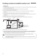
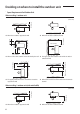
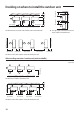
Deciding on where to install the outdoor unit Space Requirements for Outdoor Unit When installing 1 outdoor unit 2000 or more 300 or more 1500 or more ❋ When the air outlet is towards the wall 300 or more ❋ When the air outlet is opposite the wall 1500 or more 300 or more (Unit : mm) 600 or more 300 or more 300 or more 1500 or more 600 or more ❋ When 3 sides of the outdoor unit are blocked by the wall ❋ The upper part of the outdoor unit and the air outlet is towards the wall ❋ The upper par
1500 or more 300 or more 2000 or more ENGLISH 300 or more 600 or more 300 or more 300 or more 1500 or more 600 or more ❋ When 3 sides of the outdoor unit are blocked by the wall ❋ The upper part of the outdoor unit and the air outlet is towards the wall ❋ The upper part of the outdoor unit and the air outlet is opposite the wall ❋ When front and rear side of the outdoor unit is towards the wall When installing more than 1 outdoor unit 1500 or more (Unit : mm) 300 or more ❋ When the air outl
1500 or more 600 or more 600 or more ❋ When front and rear side of the outdoor unit is towards the wall 1500 or more 600 or more 3000 or more 500 or more 300 or more 500 or more Deciding on where to install the outdoor unit 300 or more 300 or more ❋ The upper part of the outdoor unit and the air outlet is towards the wall 3000 or more 300 or more ❋ When 3 sides of the outdoor unit are blocked by the wall When installing more than 1 outdoor unit (with wind baffle) 1500 or more (Unit : mm)
300 or more 1500 or more ENGLISH 600 or more 600 or more ❋ When front and rear side of the outdoor unit is towards the wall 1500 or more 600 or more 3000 or more 3000 or more 300 or more ❋ When 3 sides of the outdoor unit are blocked by the wall CAUTION t The units must be installed according to distances declared, in order to permit accessibility from each side, either to guarantee correct operation of maintenance or repairing products.
Outdoor unit installation The outdoor unit must be installed on a rigid and stable base to avoid any increase in the noise level and vibration, particularly if the outdoor unit is to be installed in a location exposed to strong winds or at a height, the unit must be fixed to an appropriate support(wall or ground). Fix the outdoor unit with anchor bolts. t The anchor bolt must be 20 mm or higher from the base surface.
Connecting the cable CAUTION t During the unit installation make first refrigerant connections and then electrical connections. If unit is uninstalled first disconnect electrical cables, then refrigerant connections. t Connect the air conditioner to grounding system before performing the electrical connection. t When installing the unit, you shouldn't use inter connection wire.
Connecting the cable Power Cable Specifications f The power cable is not supplied with air conditioner. - Select the power supply cable in accordance with relevant local and national regulations. - Wire size must comply with the applicable local and national code. - Specifications for local wiring power cord and branch wiring are in compliance with local cord.
NOTE Model AC071JXSCEH/EU AC100JXSCEH/EU AC100JXSCGH/EU AC125JXSCGH/EU Ssc[MVA] 1.96 0.46 2.98 2.98 15 ENGLISH 1. Voltage range f Units are suitable for use on electrical systems where voltage supplied to unit terminal is not below or above listed range limits 2. Maximum allowable voltage variation between phases is 2%. 3. Wire size & type must comply with the applicable local and national code. f Wire size : Based on the value of MCA. f Wire type : 60245 IEC57(IEC) or H05RN-F(CENELEC) grade or more.
Connecting the cable Between Indoor unit and Outdoor unit Connection Cable Specifications(Common in use) Power supply Power supply Max/Min(V) Indoor Power Cable 1Φ, 220-240V, 50Hz ±10% 1.5mm² , 3wires Communation Cable 0.75~1.5mm², 2wires f Power supply cords of parts of appliances for outdoor use shall not be lighter than polychloroprene sheathed flexible cord.
Wiring Diagram of Power Cable When using ELB for 1 phase and 3 phase 1 phase L ENGLISH 1(L) 2(N) N Cable tie Power Supply Electrical component box Indoor Power MCCB ELB Main power cable MCCB Communication cable 3 phase 1(L) 2(N) L1(R) L2(S) L3(T) N Indoor Unit Cable tie ❋ The appearance of the unit may be different from the picture depending on the model.
Connecting the cable Silence mode controller wiring diagram ASSY Control out Outdoor unit Silence Mode Controller Wiring Diagram of Connection Cord 1(L) 2(N) L 1(L) 2(N) 1(L) 2(N) Indoor Unit Indoor Unit N 1(L) 2(N) L1(R) L2(S) L3(T) Indoor Power Main power cable F1 F2 V1 V2 F3 F4 3 phase (4Way Type) F1 F2 V1 V2 F3 F4 1 phase (4Way Type) Cable tie N F1 Cable tie Communication cable Indoor Power 3 Phase 4 Wires power cable (AC 380 V) 18 F2 Communication cable
1 phase (Duct Type) 3 phase (Duct Type) Indoor Unit F1 F2 V1 V2 F3 Outdoor Unit 1(L) 2(N) F4 1 Indoor Unit F1 2 1(L) 2(N) L F2 V1 V2 F3 1(L) 2(N) F4 Outdoor Unit 1 2 N Cable tie Indoor Power Main power cable N ENGLISH Cable tie Indoor Power 1(L) 2(N) L1(R) L2(S) L3(T) 3 Phase 4 Wires power cable (AC 380 V) Communication cable Communication cable 1 phase (Wall mounted Type) Outdoor Unit Indoor Unit 1(L) 2(N) F1 F2 3 phase (Wall mounted Type) 1(L) 2(N) 1(L) 2(N) Indoo
Connecting the cable Connecting the Power Terminal f Connect the cables to the terminal board using the compressed ring terminal. f Cover a solderless ring terminal and a connector part of the power cable and then connect it. Silver solder B D d1 E F L d2 t Nominal Nominal dimensions dimensions Standard Standard Standard Min. Min. Max. Standard Min.
f If the terminal is loose, fire may occur caused by arc. If the terminal is connected too firmly, the terminal may be damaged. 5JHIUFOJOH 5PSRVF LHG t DN CAUTION 5.0~7.5 Communication : F1, F2 12.0~18.0 3phase AC power : 1(L), 2(N), L1(R), L2(S), L3(T), N 20.0~30.0 1phase AC power : 1(L), 2(N), L, N ENGLISH M3 M4 M5 ❋ 1N · m = 10 kgf · cm t When connecting cables, you can connect the cables to the electrical part or connect them through the holes below depending on the spot.
Connecting the cable 4. Using a crimping tool, compress the two points and flip it over and compress another two points in the same location. - The compression dimension should be 8.0. - After compressing it, pull both sides of the wire to make sure it is firmly pressed. Compression dimension f Method 1 f Method 2 Compress it 4 times. 5 mm Compress it 4 times. 5 mm 5. Wrap it with the insulation tape twice or more and position your contraction tube in the middle of the insulation tape.
Connecting the refrigerant pipe Refrigerant piping system Maximum allowable length ENGLISH Items Single installation Applicable outdoor unit models AC✴✴✴JXSC✴H Main pipe (L1) 75 m Max. height difference between outdoor and indoor units (h1) 30 m L1 indoor h1 outdoor f Temper grade and minimum thickness of the refrigerant pipe CAUTION Outer diameter [mm] Minimum thickness [mm] ø6.35 0.7 ø9.52 0.7 ø12.70 0.8 ø15.88 1.0 ø15.88 0.8 ø19.05 0.9 ø22.23 0.
Adding refrigerant (R-410A) The outdoor unit is loaded with sufficient refrigerant for the standard piping. Thus, refrigerant must be added if the piping is lengthened. This operation can only be performed by a qualified refrigeration specialist. For quantity of adding refrigerant, refer to "How to Calculate the Quantity of Adding Refrigerant" section. 1. Check that the stop valve is closed entirely. 2. Charge the refrigerant through the service port of liquid stop valve.
Important information regulation regarding the refrigerant used This product contains fluorinated greenhouse gases. Hermetically sealed system. Do not vent gases into the atmosphere. CAUTION Please fill in the following with indelible ink on the refrigerant charge label supplied with this product and on this manual. f ① : The factory refrigerant charge of the product. f ② : The additional refrigerant amount charged in the field. f ①+② The total refrigerant charge.
Adding refrigerant (R-410A) ❋ Heating operation Unit : [kPa, G] Indoor Temp.(°C) (Dry-Bulb/Wet Bulb) 27/15 20/15 13/10 3048 2924 2636 2430 2042 3030 2580 2316 2127 1784 2811 2248 2007 1835 1794 Outdoor Temp.(°C) 24 7 0 -5 -25 f AC100JXSCEH/EU, AC100JXSCGH/EU ❋ Cooling operation Unit : [kPa, G] Indoor Temp.(°C) (Dry-Bulb/Wet Bulb) 32/23 27/19 21/15 1280 1006 931 941 1002 1181 905 831 838 928 1054 812 749 738 789 Outdoor Temp.
Connecting up and removing air in the circuit CAUTION t When installing, make sure there is no leakage. When recovering the refrigerant, ground the compressor first before removing the connection pipe. If the refrigerant pipe is not properly connected and the compressor works with the service valve open, the pipe inhales the air and it makes the pressure inside of the refrigerant cycle abnormally high. It may cause explosion and injury. 2.
Connecting up and removing air in the circuit 6. Set valve cork of both liquid side and gas side of packed valve to the open position. 7. Mount the valve stem nuts and the service port cap to the valve, and tighten UIFN BU UIF UPSRVF PG LHGtDN XJUI B UPSRVF XSFODI 8. Check for gas leakage. f At this time, especially check for gas leakage from the 3-way valve’s stem nuts(A port), and from the service port cap.
Cutting/Flaring the pipes 1. Make sure that you have the required tools available. (pipe cutter, reamer, flaring tool and pipe holder) 2. If you wish to shorten the pipes, cut it with a pipe cutter, taking care to ensure that the cut edge remains at a 90° angle with the side of the pipe. Refer to the illustrations below for examples of edges cut correctly and incorrectly. Rough Burr ENGLISH Oblique 3. To prevent any gas from leaking out, remove all burrs at the cut edge of the pipe, using a reamer. 4.
Performing leak tests LEAK TEST WITH NITROGEN (before opening valves) In order to detect basic refrigerant leaks, before recreating the vacuum and recirculating the R-410A, it’s responsable of installer to pressurize the whole system with nitrogen (using a cylinder with pressure reducer) at a pressure above 40 bar (gauge). LEAK TEST WITH R-410A (after opening valves) Before opening valves, discharge all the nitrogen into the system and create vacuum.
Refrigerant pipe work Insulating the pipes Once you have checked that there are no leaks in the system, you can insulate the piping and hose. NOTE CAUTION ENGLISH 1. To avoid condensation problems, place an insulator around each refrigerant pipe. t When insulate the pipe, be sure to overlap the insulation. t The insulation has to be produced in full compliance of European regulation reg.
Refrigerant pipe work f When installing insulation in places and conditions below, use the same insulation that is used for high humidity conditions. - High humidity places such as shoreline, hot spring, near lake or river, and ridge (when the part of the building is covered by earth and sand.) - Restaurant ceiling, sauna, swimming pool etc. - The ceiling frequently exposed to moisture and cooling is not covered. e.g.
Using stop valve To Open the Stop Valve Cap ENGLISH 1. Open the cap and turn the stop valve counterclockwise by using a hexagonal wrench. 2. Turn it until the axis is stopped. Service port NOTE t Do not apply excessive force to the stop valve and always use special instruments. Otherwise, the stopping box can be damaged and the back sheet can leaks. t If the watertight sheet leaks, turn the axis back by half, tighten the stopping box, then check the leakage again.
Pump down Procedure Pump down will be carried out when an evaporator is replaced or when the unit is relocated in another area. 1. Remove the cap from the low pressure side. 2. Turn the low pressure side valve clockwise to close and connect a pressure gauge (low pressure side) to the service valve, and open the valve again. 3. Set the unit to the cooling Test mode by pushing K2 button (Check if the compressor is operating.) 4. Turn the high pressure side valve clockwise to close. 5.
Checking correct grounding If the power distribution circuit does not have a grounding or the grounding does not comply with specifications, an grounding electrode must be installed. The corresponding accessories are not supplied with the air conditioner. NOTE t The grounding wire for the telephone line cannot be used to ground the air conditioner. Carbon plastic Steel core Terminal M4 PVC-insulated green/ To grounding screw yellow wire 50 cm 30 cm 3.
Testing operations 1. Check the power supply between the outdoor unit and the auxiliary circuit breaker. f 1 phase power supply : L, N f 3 phases power supply : R,S,T,N 2. Check the indoor unit. 1) Check that you have connected the power and communication cables correctly. (If the power cable and communication cables one mixed up or connected incorrectly, the PCB will be damaged.) 2) Check the thermistor sensor, drain pump/hose, and display are connected correctly. 3.
6. View Mode : When the K4 switch is pressed, you can see information about our system state as below.
Testing operations 7. DIP switch option ON ON 1 2 3 4 1 SW507 2 3 4 SW508 f SW507 option On (default) Off Switch 1 - - Switch 2 Disable snow prevention control Enable snow prevention control Switch 3 Silence mode option Switch 4 Switch 3 Switch 4 Operation On On Disable Silence mode On Off Silence mode step 1 Off On Silence mode step 2 Off Off Silence mode step 3 ❋ When snow prevention mode is in use, eco mode (standby mode) will not work.
Installing the wind baffle If you operate the cooling operation of air conditioner in the condition where ambient temperature is lower than -5 °C DB(Dry bulb), or the outdoor unit might be faced with strong wind directly, the wind baffle should be installed to prevent the outdoor unit fan from operating in reverse way. ENGLISH Make holes on both sides and attach the wind baffle using screws. Partition 625.7 mm 16.
Troubleshooting The table below give indication about self diagnostic routine. Some of error code requires activities exclusively for Authorized Service Center. Outdoor unit If an error occurs during the operation, it is displayed on the outdoor unit PCB LED, both MAIN PCB and INVERTER PCB. No.
No. Error Code Meaning Remarks E422 Blockage detected on high pressure pipe 19 E425 Reverse phase or open phase Check whether 3 phase is reversed or opened.
Troubleshooting 42 No. Error Code Meaning Remarks 37 E475 Error on inverter fan 2 FAN2 ERROR 38 E484 PFC Overload (Over current) Error Check Outdoor Inverter PBA. 39 E485 Error on input current sensor of inverter 1 (Short or Open) 40 E500 IPM over heat error on inverter 1 Check Outdoor Inverter PBA.
Appendix Type Model Net weight Net dimension (W*D*H) 96.
COMMISSION DELEGATED REGULATION (EU) No 626/2011i) PRODUCT FICHE (ENERGY LABELLING OF AIR CONDITIONERS)ii) A B Supplier's name Model name (Indoor/Outdoor) C Sound Power Level (Indoor/Outdoor) - Samsung Electronics Co.. Ltd. AC071JN4CEH/ AC071JXSCEH AC100JN4CEH/ AC100JXSCEH AC100JN4CEH/ AC100JXSCGH AC071KNADEH/ AC071JXSCEH dB(A) 53/65 59/66 59/66 61/65 D Refrigerant name1) - R-410A R-410A R-410A R-410A E GWP - 2088 2088 2088 2088 F SEER - 6.7 7.0 7.0 6.
COMMISSION DELEGATED REGULATION (EU) No 626/2011i) PRODUCT FICHE (ENERGY LABELLING OF AIR CONDITIONERS)ii) A Model name (Indoor/Outdoor) C Sound Power Level (Indoor/Outdoor) - Samsung Electronics Co.. Ltd. AC071JNMCEH/ AC071JXSCEH AC100JNMCEH/ AC100JXSCEH AC100MNTDEH/ AC100JXSCEH AC100JNMCEH/ AC100JXSCGH AC100MNTDEH/ AC100JXSCGH dB(A) 56/65 61/66 65/66 61/66 65/66 D Refrigerant name1) - R-410A R-410A R-410A R-410A R-410A E GWP - 2088 2088 2088 2088 2088 F SEER - 6.1 6.
COMMISSION DELEGATED REGULATION (EU) No 626/2011i) PRODUCT FICHE (ENERGY LABELLING OF AIR CONDITIONERS)ii) [ESPAÑOL-ES] iv [ITALIANO-IT] [PORTUGUÊS-PT] Nombre del proveedor Nom du fournisseur Nome del Fornitore Nome do fornecedor B Nombre del modelo (unidad interior/exterior) Nom du modèle (intérieur/extérieur) Nome del Modello (Unità Interna/Unità Esterna) Nome do modelo (interior/exterior) C Nivel de potencia acústica (interior/exterior) Niveau de puissance acoustique (intérieur/extérieur)
PRODUCT FICHE (ENERGY LABELLING OF AIR CONDITIONERS)ii) [DEUTSCH-DE] [NEDERLANDS-NL] Naam van de leverancier [POLSKI-PL] Όνομα προμηθευτή Nazwa dostawcy B Modellbezeichnung (Innen-/Außengerät ) Ονομασία μοντέλου Modelnaam (binnen/buiten) (εσωτερικού χώρου/εξωτερικού χώρου) Nazwa modelu (Wewnętrzny/zewnętrzny) C Schallleistungspegel (innen/außen) Στάθμη ηχητικής ισχύος (εσωτερικού/εξωτερικού χώρου) Geluidsniveau (binnen/buiten) Poziom mocy akustycznej (Wewnętrzna/zewnętrzna) D Name des Kältemi
COMMISSION DELEGATED REGULATION (EU) No 626/2011i) PRODUCT FICHE (ENERGY LABELLING OF AIR CONDITIONERS)ii) [MAGYAR-HU] [ROMÂNĂ-RO] Hladina akustického výkonu (vnitřní/venkovní) Název chladiva1) GWP SEER Třída energetické účinnosti (SEER) QCE2) (období chlazení) Pdesignc SCOP (průměr) Třída energetické účinnosti SCOP (průměrný) QHE3) období topení (průměrný) Pdesignh (průměr) Záložní topný výkon (průměrný) Udávaný výkon (průměrný) Další topné sezony vhodné k použití SCOP (teplejší) Třída energetické účinno
PRODUCT FICHE (ENERGY LABELLING OF AIR CONDITIONERS)ii) A B C K L M N O P Q R [SLOVENČINA-SL] Názov dodávateľa Názov modelu (vnútorné/vonkajšie) Hladina akustického výkonu (vnútorná/vonkajšia) Chladivo1) GWP SEER Trieda energetickej účinnosti (SEER) QCE2) (sezóna chladenia) Pdesignc SCOP (Priemerná) Trieda energetickej účinnosti SCOP (Priemerná) QHE3) sezóna vykurovania (Priemerná) Pdesignh (Priemerná) Zálohovanie vykurovací výkon (Priemerná) Deklarovaný chladiaci výkon (Priemerná) Iné sezóny vykurovania,
COMMISSION DELEGATED REGULATION (EU) No 626/2011i) PRODUCT FICHE (ENERGY LABELLING OF AIR CONDITIONERS)ii) [SVENSKA-SV] Leverantörens namn Tavarantoimittajan nimi B Modellnamn (inomhus/utomhus) Mallin nimi (sisä/ulko) C Ljudnivå (inomhus/utomhus) Äänitehotaso (sisä/ulko) D E F G H I J Köldmedium1) GWP SEER K L M N O [LATVIEŠU-LV] Piegādātāja nosaukums Mudeli nimi (sisetingimused/välistingimused) Helivõimsuse tase (sisetingimused/välistingimused) Modeļa nosaukums (iekštelpu/ārtelpu) Skaņas inten
PRODUCT FICHE (ENERGY LABELLING OF AIR CONDITIONERS)ii) [LIETUVIŲ KALBA-LT] A B Naziv dobavljača Naziv modela (unutršnja jedinica/spoljašnja jedinica) Garso galios lygis (patalpose / lauke) Nivo buke (unutrašnja/spoljna jedinica) Šaldalo pavadinimas1) GWP SEER Energijos suvartojimo efektyvumo klasė (SEER) QCE2) (vėsinimo sezonas) Pdesignc SCOP (vidutinis klimatas) Naziv rashladnog sredstva1) GWP SEER Klasa energetske efikasnosti (SEER) QCE2) (sezona hlađenja) Pdesignc SCOP (Prosečno) K Energijos suva
COMMISSION DELEGATED REGULATION (EU) No 626/2011i) PRODUCT FICHE (ENERGY LABELLING OF AIR CONDITIONERS)ii) [ESPAÑOL-ES] 1. Las fugas de refrigerante contribuyen al cambio climático. Cuanto mayor sea el potencial de calentamiento global (GWP) de un refrigerante, más contribuirá a dicho calentamiento su vertido a la atmósfera. Este aparato contiene un líquido refrigerante con un GWP igual a [2088].
PRODUCT FICHE (ENERGY LABELLING OF AIR CONDITIONERS)ii) [DEUTSCH-DE] [EΛΛHNIKA-EL] 1. Διαρροή ψυκτικού μέσου συμβάλλει στην κλιματική αλλαγή. Εάν διαρρεύσει στην ατμόσφαιρα ψυκτικό μέσο με χαμηλότερο δυναμικό θέρμανσης του πλανήτη (GWP) θα συμβάλει λιγότερο στην υπερθέρμανση του πλανήτη από ψυκτικό με υψηλότερο GWP. Αυτή η συσκευή περιέχει ψυκτικό μέσο με GWP ίσο με [2088].
COMMISSION DELEGATED REGULATION (EU) No 626/2011i) PRODUCT FICHE (ENERGY LABELLING OF AIR CONDITIONERS)ii) [MAGYAR-HU] 1. A hűtőközeg-szivárgás fokozza az éghajlatváltozást. Az alacsonyabb globális felmelegedési potenciállal (GWP) rendelkező hűtőközegek kevésbé járulnak hozzá a globális felmelegedéshez, ha a légkörbe jutnak, mint a magasabb együtthatójú típusok. A berendezés [2088] értékű globális felmelegedési potenciállal (GWP) rendelkező, folyékony halmazállapotú hűtőközeget tartalmaz.
PRODUCT FICHE (ENERGY LABELLING OF AIR CONDITIONERS)ii) [БЪЛГАРСКИ-BG] [HRVATSKI-HR] 1. Istjecanje rashladnih sredstava doprinosi klimatskim promjenama. U slučaju ispuštanja u atmosferu rashladno sredstvo s nižim potencijalom globalnog zagrijavanja (GWP) manje bi utjecalo na globalno zagrijavanje od rashladnog sredstva s višim GWP-om. Taj uređaj sadrži rashladnu tekućinu s GWP-om jednakim [2088].
COMMISSION DELEGATED REGULATION (EU) No 626/2011i) PRODUCT FICHE (ENERGY LABELLING OF AIR CONDITIONERS)ii) [SVENSKA-SV] 1. Läckande köldmedium bidrar till klimatförändringen. Köldmedier med lägre global uppvärmningspotential (GWP) bidrar mindre till den globala uppvärmningen än köldmedier med högre GWP-värde, om de skulle läcka ut i atmosfären. Den här enheten innehåller ett köldmedium med ett GWP-värde som är lika med [2088].
PRODUCT FICHE (ENERGY LABELLING OF AIR CONDITIONERS)ii) [LATVIEŠU-LV] [LIETUVIŲ KALBA-LT] 1. Šaldalo protėkis turi įtakos klimato kaitai. Į atmosferą ištekėjęs šaldalas, kurio globalinis šiltėjimo potencialas (GWP) mažesnis, globaliniam atšilimui turi mažiau įtakos nei šaldalas, kurio GWP didesnis. Šiame prietaise yra šaldymo skysčio, kurio GWP lygus [2088].
Memo
Memo ENGLISH 59
SAMSUNG ELECTRONICS CO., LTD. 107, Hanamsandan 6beon-ro, Gwangsan-gu, Gwangju-si, Korea 62218 501# Suhong East Road, Industrial Park, Suzhou, Jiagsu, China Samsung Electronics Service Department PO Box 12987, Blackrock, Co. Dublin. Ireland or Blackbushe Business Park, Yateley, GU46 6GG.