
Specifications


Quick Start-Up Guide
MPC8555E Configurable Development System Reference Manual, Rev. 1
Freescale Semiconductor 2-7
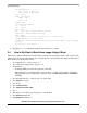
10. erase ff800000 ffdfffff
11. cp.b 1000000 ff800000 1fffff
12. cp.b 2000000 ffa00000 3fffff
Steps 13 to 16 are required to update the environment variables.
13. setenv bootargs root=/dev/ram rw console=ttyS1,115200
14. setenv bootcmd bootm ff800000 ffa00000
15. saveenv
16. reset
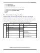
2.5 Default Switch Configuration Table
The CDS system has several options for the switch settings to allow users to easily change the
configuration. Table 2-1, Table 2-2, and Table 2-3 show the default switch settings for targeted
applications. For the processor board (CPU card) switches shown in Table 2-1 and the carrier board
switches shown in Table 2-2, in order to set an option value to 1, set the switch to ON; to set an option
value to 0, set the switch to OFF. For the Arcadia board switches shown in Table 2-3, in order to set an
option value to 1, set the switch to ON; to set an option value to 0, set the switch to OFF.
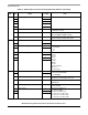
Table 2-1. Default Status of Processor Board (CPU Card) Switches
SW Bit Name
Default
(1 = ON)
Note
1 1 PCI1 bus impedance 1 0 25 Ω
142 Ω (Default)
2 PCI1 debug enable 1 Default
3 DDR debug enable 1
4 Memory debug enable 1
5 Local bus hold LWE[0:1] 1 00 One extra delay
01 Two extra delays
10 Three extra delays
11 Default/specified AC timing
61
7 PCI1 clock select 1 1 Sync (use SYSCLK) default
0 Async (use PCI1CLK)
8 PCI2 clock select 0 1 Sync (use SYSCLK)
0 Async (use PCI2CLK) default