
Specifications


CDS Carrier Architecture
MPC8555E Configurable Development System Reference Manual, Rev. 1
Freescale Semiconductor 3-25
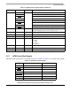
2. Set the WatchDog Register (offset 0x1FF7 from the LCS2* base (typically 0xFD00_0000)) to:
RB(1:0) = %00 (1/16 second resolution)
BMB(4:0) = %00001 (minimum delay)
WDS = %1 (assert NVRST (which will assert HRESET to the processor and other devices)).
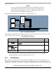
NOTE
The system startup code must initialize the WatchDog timer by writing a
zero to the WatchDog register. Otherwise, the system will continually reset
until power is cycled (because this is, as you might have guessed, a
watchdog timer).
3.12 I2C
CDS makes extensive use of the I2C bus for a variety of purposes, including:
• System configuration
• Non-PCI (local) clock speed selection
• Remote control bus
• Module and system identification
Many of these functions are also available on the daughtercard, so familiarity with the CDC card in use is
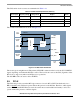
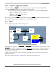
assumed. All current carrier cards implement the architecture of the I2C bus as shown in Figure 3-18.
Figure 3-18. CDS Carrier I2C Architecture
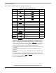
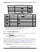
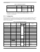
Table 3-24 contains a summary of the various features of the I2C devices. Refer to the programming
manual for detailed programming information, and refer to other sections of this manual for details on how
the I2C-control features are implemented (specifically, Section 3.13, “Configuration”).
Debug
Control
Conn.
Remote
Control
Drive
CADMUS
Configs
ID
EEPROM
Buffer
I2C
To
Daughtercard
Offboard