DB98_16444A(1)_CO 2/9/04 1:47 PM Page 1 2004. 2 WALL MOUNTED TYPE Manual MODEL LINE-UP SPECIFICATIONS 2 0 0 4 .
DB98_16444A(1)_1 2/9/04 10:04 AM Page 1 1 Model Line-Up 1-1. Model Identification 1-2.
DB98_16444A(1)_1 2/9/04 10:04 AM Page 2
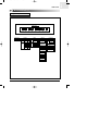
DB98_16444A(1)_1 2/9/04 10:04 AM Page 3 MODEL LINE-UP Model Identification 1-1. Model Identification Wall Mounted Type Air Conditioner ● Standard type Model Code Model Name I Q V 09 A 1 M E ! @ # $ % ^ & * $ Capacity # Tech Sub_Set Set A None Indoor I Tropical T Outdoor X INV+R22 V R22+BLDC D Low Temp.
DB98_16444A(1)_1 1 2/9/04 10:04 AM Page 4 MODEL LINE-UP Model Identification (cont.
DB98_16444A(1)_1 2/9/04 10:04 AM Page 5 MODEL LINE-UP Model Identification (cont.
DB98_16444A(1)_1 1 2/9/04 10:04 AM Page 6 MODEL LINE-UP Model Line-Up 1-2.
DB98_16444A(1)_1 2/9/04 10:04 AM Page 7 2 Specifications 2-1.
DB98_16444A(1)_1 2/9/04 10:04 AM Page 8
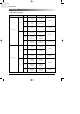
DB98_16444A(1)_1 2/9/04 10:04 AM Page 9 SPECIFICATIONS Table 2-1. Table Model Item SH07APG Indoor unit Type SH09APG Outdoor unit Indoor unit SH12APG Outdoor unit Indoor unit Outdoor unit Wall-mounted Wall-mounted Wall-mounted 2.47 2.70 3.50 2.46 2.90 3.80 0.9 1.4 1.9 Cooling kW Heating |/h Dehumidifying Performance Air Volume Noise 3 m /min 6.5 dB 37 50 40 24 8.2 51 43 24 53 3.21 3.21 3.42 3.41 3.
DB98_16444A(1)_1 2 2/9/04 10:04 AM Page 10 SPECIFICATIONS Table (cont.) Table(cont.) Model Item SH07AS2 Indoor unit Type SH09AS2 Outdoor unit Indoor unit SH12AS4 Outdoor unit Indoor unit Outdoor unit Wall-mounted Wall-mounted Wall-mounted 2.30 2.70 3.50 2.40 2.90 3.80 0.9 1.4 1.9 Cooling kW Heating |/h Dehumidifying Performance Air Volume Noise 3 m /min 6.2 22 6.8 22 8.2 24 dB 36 50 39 51 43 53 2.95 2.87 2.82 3.24 3.22 3.
DB98_16444A(1)_1 2/9/04 10:04 AM Page 11 3 Outline & Dimension 3-1. Indoor Unit 3-2.
DB98_16444A(1)_1 2/9/04 10:04 AM Page 12
DB98_16444A(1)_1 2/9/04 10:04 AM Page 13 OUTLINE & DIMENSION Indoor Unit 3-1.
DB98_16444A(1)_1 Page 14 OUTLINE & DIMENSION Indoor Unit (cont.
DB98_16444A(1)_1 2/9/04 10:04 AM Page 15 OUTLINE & DIMENSION Outdoor Unit 3-2. Outdoor Unit ✳ The figure in parentheses means 12K.
DB98_16444A(1)_1 2/9/04 10:04 AM Page 16 MEMO 16 | SAMSUNG
DB98_16444A(1)_1 2/9/04 10:04 AM Page 17 4 Performance Data 4-1.
DB98_16444A(1)_1 2/9/04 10:04 AM 18 | SAMSUNG Page 18
DB98_16444A(1)_1 2/9/04 10:04 AM Page 19 PERFORMANCE DATA Performance Data 4-1. Performance Data 4-1-1. Capacity ● 7,000BTU ■ Capacity Distribution 3.0 DB32.4/WB24.0 DB30.6/WB22.5 DB27.0/WB19.0 DB24.0/WB17.0 DB21.5/WB15.0 2.0 1.0 4.5 Indoor Temp. 25 35 Heating Capacity(kW) Cooling Capacity(kW) 4.0 3.5 DB15.0 DB20.0 DB25.0 2.5 1.5 1.0/0.0 45 Indoor Temp. Outdoor Temp.(DB C) 7.0/6.0 20.0/15.0 Outdoor Temp.
DB98_16444A(1)_1 Page 20 PERFORMANCE DATA Performance Data (cont.) Capacity (cont.) ● 9,000BTU ■ Capacity Distribution Indoor Temp. 3.0 DB32.4/WB24.0 DB30.6/WB22.5 2.0 DB27.0/WB19.0 DB24.0/WB17.0 DB21.5/WB15.0 Heating Capacity(kW) Cooling Capacity(kW) 4.0 1.0 25 35 4.5 Indoor Temp. 3.5 DB15.0 DB20.0 DB25.0 2.5 1.5 1.0/0.0 45 7.0/6.0 20.0/15.0 Outdoor Temp.(DB/WB C) Outdoor Temp.(DB C) ■ Power consumption Distribution Indoor Temp. 1100.
DB98_16444A(1)_1 2/9/04 10:04 AM Page 21 PERFORMANCE DATA Performance Data (cont.) Capacity (cont.) ● 12,000BTU ■ Capacity Distribution 5.5 Indoor Temp. 4.0 DB32.4/WB24.0 DB30.6/WB22.5 3.0 DB27.0/WB19.0 DB24.0/WB17.0 DB21.5/WB15.0 Heat Capacity(kW) Cooling Capacity(kW) 5.0 Indoor Temp. DB15.0 DB20.0 DB25.0 4.5 3.5 2.0 2.5 35 25 45 1.0/0.0 Outdoor Temp.(DB C) 7.0/6.0 20.0/15.0 Outdoor Temp.(DB/WB C) ■ Power consumption Distribution 1600 Indoor Temp.
DB98_16444A(1)_1 Page 22 PERFORMANCE DATA Performance Data (cont.) 4-1-2. C00ling Capacity Correction Factors ● 7,000BTU 2590.4 2467.0 Capacity(W) 2343.7 2220.3 2097.0 1973.6 1850.3 1726.9 7.5 15.0 Piping Length(m) 847.6 831.0 814.4 797.8 781.1 Input(W) 4 2/9/04 10:04 AM 764.5 747.9 731.3 714.7 698.0 7.5 15.
DB98_16444A(1)_1 2/9/04 10:04 AM Page 23 PERFORMANCE DATA Performance Data (cont.) C00ling Capacity Correction Factors(cont.) ● 9,000BTU 2650 2600 2550 Capacity(W) 2500 2450 2400 2350 2300 2250 2200 7.5 15.0 Piping Length(m) 898.5 898.0 897.5 897.0 Input(W) 896.5 896.0 895.5 895.0 894.5 894.0 893.5 7.5 15.
DB98_16444A(1)_1 Page 24 PERFORMANCE DATA Performance Data (cont.) C00ling Capacity Correction Factors(cont.) ● 12,000BTU 3550.0 3500.0 Capacity(W) 3450.0 3400.0 3350.0 3300.0 3250.0 7.5 15 Piping Length(m) 1185 1180 1175 Input(W) 4 2/9/04 10:04 AM 1170 1165 1160 1155 7.5 15 Piping Length(m) ✳Refrigerant must be added if the piping length is more than 7.5metres. ✳In case of 7K and 9K models, 20g of refrigerant 'R410A' must be added for each extra metre.
DB98_16444A(1)_1 2/9/04 10:04 AM Page 25 PERFORMANCE DATA Performance Data (cont.) 4-1-3. Low Pressure Distribution(Cooling Mode) Low pressure(kg/cm G) ● 7,000BTU 12.0 Indoor Temp. DB32.4/WB24.0 DB30.6/WB22.5 10.0 DB27.0/WB19.0 DB24.0/WB17.0 DB21.5/WB15.0 8.0 6.0 25 35 45 Outdoor Temp.(DB C) ● 9,000BTU Low pressure(kg/cm G) 12.0 Indoor Temp. DB32.4/WB24.0 DB30.6/WB22.5 10.0 DB27.0/WB19.0 DB24.0/WB17.0 DB21.5/WB15.0 8.0 6.0 25 35 45 Outdoor Temp.
DB98_16444A(1)_1 2/9/04 10:04 AM Page 26 MEMO 26 | SAMSUNG
DB98_16444A(1)_1 2/9/04 10:04 AM Page 27 5 Installation 5-1. Selecting Area for Installation 5-2. Installation Diagram of Indoor Unit and Outdoor Unit 5-3. Performing Leak Tests 5-4. Placing the Indoor Unit in Position 5-5.
DB98_16444A(1)_1 2/9/04 10:04 AM Page 28
DB98_16444A(1)_1 2/9/04 10:04 AM Page 29 INSTALLATION Selecting Area for Installation Select an area for installation that is suitable to customer’s needs. 5-1. Selecting Area for Installation 5-1-1. Indoor Unit 1. Make sure that you install the indoor unit in an area providing good ventilation. It must not be blocked by an obstacle affecting the airflow near the air inlet and the air outlet. 2.
DB98_16444A(1)_1 5 2/9/04 10:04 AM Page 30 INSTALLATION Selecting Area for Installation (cont.) 5-1-2. Outdoor Unit 1. Make sure that you install the outdoor unit in area not exposed to the rain or direct sun light.(Install a separate sunblind if exposed to direct sun light.) 2. Make sure that you install the outdoor unit in area allowing the good air moment, not amplifying noise or vibration, especially to avoid disturbing neighbors. (Fix the unit firmly if it is mounted in a high place.) 3.
DB98_16444A(1)_1 2/9/04 10:04 AM Page 31 INSTALLATION Installation Diagram of Indoor Unit and Outdoor Unit 5-2. Installation Diagram of Indoor Unit and Outdoor Unit A B Indoor unit gas leak test Drain hose installation Cut the piping hole sloped Cut theslightly piping hole 3 Indoor unit sloped slightly 1 Piping Vinyl tape 2 Piping may be laid to the rear, left, right or down. Left Right Rear Rear • Wrap the refrigerant pipes and the drain hose up in the absorbent pad and the vinyl tape.
DB98_16444A(1)_1 Page 32 INSTALLATION Installation Diagram of Indoor Unit and Outdoor Unit (cont.) 5-2-1. Fixing the Installation Plate 1. Determine the position of the pipe and drain hose hole referring to the right figure and drill the hole with an inner diameter of 65mm so that it slants slightly downwards. Pipe hole (Ø65mm) 2. If you are fixing the indoor unit to a… Then follow Steps… 3. Window frame 4 to 6. 3.
DB98_16444A(1)_1 2/9/04 10:04 AM Page 33 INSTALLATION Installation Diagram of Indoor Unit and Outdoor Unit (cont.) 5-2-3. Connecting the Assembly Cable (Cooling Only) The outdoor unit is powered from the indoor unit via the assembly cable. (7K/9K/12K) 1. Extend the assembly cable if necessary. 2. Open the front grille by pulling on the tab on the lower right and left sides of the indoor unit. 3. Remove the screw securing the connector cover. 4.
DB98_16444A(1)_1 5 2/9/04 10:04 AM Page 34 INSTALLATION Installation Diagram of Indoor Unit and Outdoor Unit (cont.) 5-2-5. Installing and Connecting the Indoor Unit Drain Hose Care must be taken when installing the drain hose for the indoor unit to ensure that any condensed water is correctly drained outside. When passing the drain hose through the 65mm hole drilled in the wall, check that none of the following situation occur. 5cm less The hose must NOT slope upwards.
DB98_16444A(1)_1 2/9/04 10:04 AM Page 35 INSTALLATION Installation Diagram of Indoor Unit and Outdoor Unit (cont.) 5-2-6. Flare Modification ● TOOLS USED ● FLARE MODIFICATION PROCEDURE 1. Cut the pipe using a pipe cutter. Oblique 90 2. Remove burrs at the tip of the pipe cut. Roughness Burr Pipe Reamer CAUTION • Burrs not removed may result in leakage of gas. 3. Insert a flare nut into the pipe and modify flare. * Unproper flaring D A Outer diameter A(mm) ø6.35mm 1.3 ø9.52mm 1.8 ø12.
DB98_16444A(1)_1 5 2/9/04 10:04 AM Page 36 INSTALLATION Installation Diagram of Indoor Unit and Outdoor Unit (cont.) 5-2-7. Air-Purge Procedure The outdoor unit is loaded with sufficient R22 refrigerant for 5 metres of piping. The air in the indoor unit and in the pipe must be purged. If air remains in the refrigeration pipes, it will affect the compressor, reduce to cooling/heating capacity and could lead to a malfunction. Refrigerant for air purging is not charged in the outdoor unit.
DB98_16444A(1)_1 2/9/04 10:04 AM Page 37 INSTALLATION Installation Diagram of Indoor Unit and Outdoor Unit (cont.) 6. Set valve cork of both liquid side and gas side of packed valve to the open position. 7. Mount the valve stem nuts and the service port cap to the valve, and tighten them at the torque of 183kgf.cm with a torque wrench. 8. Check for gas leakage. ◆ At this time, especially check for gas leakage from 3-Way valve’s stem nuts, and from the service port cap.
DB98_16444A(1)_1 5 2/9/04 10:04 AM Page 38 INSTALLATION Installation Diagram of Indoor Unit and Outdoor Unit (cont.) 5-2-8. Refrigerant Refill ● Refill an air-conditioner with refrigerant when refrigerant has been leaked at installing or using. 1 Purge air(for new installation only). ▼ 2 Turn the 3-Way valve clockwise to close, connect the pressure gauge (low pressure side) to the service valve, and open the 3-Way valve again.
DB98_16444A(1)_1 2/9/04 10:04 AM Page 39 INSTALLATION Installation Diagram of Indoor Unit and Outdoor Unit (cont.) 5-2-9. Refrigerant Adjustment Class At installation Connection Pipe Length Standard 7.5m At service Air-Purge Method Refrigerant Adjustment Refer to the detailed Air-Purge Procedure Unnecessary Air-Purge Method Refrigerant Quantity Purge air using a vacuum pump or an additional refrigerant cylinder. Add "A" of refrigerant (R410A) for every 1m. Max.
DB98_16444A(1)_1 5 2/9/04 10:04 AM Page 40 INSTALLATION Installation Diagram of Indoor Unit and Outdoor Unit (cont.) 5-2-11. "Pump down" Procedure Pump down will be carried out when an evaporator is replaced or when the unit is relocated in another area. 1 Remove the caps from the 2-Way valve and the 3-Way valve. ▼ 2 Turn the 3-Way valve clockwise to close and connect a pressure gauge (low pressure side) to the service valve, and open the 3-Way valve again.
DB98_16444A(1)_1 2/9/04 10:04 AM Page 41 INSTALLATION Performing Leak Tests 5-3. Performing Leak Tests ● Before completing the installation (insulation of the cable, hose and piping and fixing of the indoor unit to the installation plate), you must check that there are no gas leaks. To check for gas leaks on the... Then, using a leak detector, check the... Indoor unit Flare nuts at the end of sections C and D. Outdoor unit Valves on sections A and B.
DB98_16444A(1)_1 5 2/9/04 10:04 AM Page 42 INSTALLATION Placing the Indoor Unit in Position 5-4. Placing the Indoor Unit in Position ● Once you have checked that there are no leaks in the system, you can insulate the piping, hose and cables and place the indoor unit on the installation plate. 1. To avoid condensation problems, place heat-resistant polyethylene foam separately around each refrigerant pipe in the lower part of the indoor unit. 2.
DB98_16444A(1)_1 2/9/04 10:04 AM Page 43 INSTALLATION Checking and Testing Operations 5-5. Checking and Testing Operations ● To complete the installation, perform the following checks and tests to ensure that the air conditioner is operating correctly. ■ PREMIUM 1.
DB98_16444A(1)_1 5 2/9/04 10:04 AM Page 44 INSTALLATION Checking and Testing Operations (cont.) ■ DELUXE 1. Review all the following elements in the installation: ◆ Installation site strength ◆ Piping connection tightness to detect any gas leakages ◆ Connection wiring ◆ Heat-resistant insulation of the piping ◆ Drainage ◆ Earthing wire connection ◆ Correct operations (follow the steps below) 2. Press the On/Off button. Result ◆ The indicator lights on the indoor unit flash at half-second intervals.
DB98_16444A(1)_1 2/9/04 10:04 AM Page 45 6 Features & Operation 6-1. The Feature of key in Remote Control 6-2. Details for Operation Property 6-3. Operating Recommendations 6-4.
DB98_16444A(1)_1 2/9/04 10:04 AM Page 46
DB98_16444A(1)_1 2/9/04 10:04 AM Page 47 FEATURES & OPERATION The Feature of key in Remote Control 6-1. The Feature of key in Remote Control 6-1-1. S✳07APG / S✳09APG / S✳12APG No 1 FUNCTION OF KEY NAMED OF KEY (On/Off) (On/Off) On/Off button. Press the button to stop or run the air conditioner. (UP) Temperature adjustment button(UP). To increase the temperature by the pressing the temperature button. (DOWN) Temperature adjustment button(DOWN).
DB98_16444A(1)_1 6 2/9/04 10:04 AM Page 48 FEATURES & OPERATION The Feature of key of Remote Control (cont.) The Feature of key in Remote Control (cont.) No NAMED OF KEY 9 10 FUNCTION OF KEY Anion button. Press the button to generate ion from the air conditioner. On Timer button. The On Timer enables you to switch on the air conditioner automatically after a given period of time that is from 30 minutes to 24 hours. To set the operating time, press the time display. 11 Off Timer button.
DB98_16444A(1)_1 2/9/04 10:04 AM Page 49 FEATURES & OPERATION The Feature of key of Remote Control (cont.) 6-1-2. S✳07AS2 / S✳09AS2 / S✳12AS4 No NAMED OF KEY FUNCTION OF KEY 1 On/Off & Timer Set/Cancel button. Press the button to stop and run the air conditioner or On/Off timer set up. 2 Mode selection button. Each time you press this button, Mode is changed in the following order. : Auto Mode : Fan Only : Cool Mode : Heat Mode : Dry Mode (UP) Temperature adjustment button(UP).
DB98_16444A(1)_1 6 2/9/04 10:04 AM Page 50 FEATURES & OPERATION Details for Operation Property 6-2. Details for Operation Property 1. AUTO MODE : In this mode, operation mode(COOL, HEAT) is selected automatically by the room temperature of initial operation. √ In case of Heat pump model.
DB98_16444A(1)_1 2/9/04 10:04 AM Page 51 FEATURES & OPERATION Details for Operation Property (cont.) 9. SWING : BLADE-H is rotated vertically by the stepping motor. • S✳07APG / S✳09APG / S✳12APG • *Swing Set : Press the button under the remote control is displayed on LCD the and the blades move up and down. If the one more time press the button, blades location is stop.
DB98_16444A(1)_1 6 2/9/04 10:04 AM Page 52 FEATURES & OPERATION Details for Operation Property (cont.) 6-2-1. Cooling Mode Operating When selecting the Cooling Mode Operation, the unit will operate according to the setting by the remote controller and the operation is as well as the following. Room temperature can be set in 1°C steps in the range of 18 to 30°C. Room Temp.(°C) Ts+1 Ts Time ON Compressor ON OFF ♦ Ts means Remote Controller setting Temperature 6-2-2.
DB98_16444A(1)_1 2/9/04 10:04 AM Page 53 FEATURES & OPERATION Details for Operation Property (cont.) 6-2-4. Sleeping Operation ● AT COOLING MODE 6h When you set the sleep mode, the following movement will start to avoid over cooling. ◆ The indoor fan speed is fixed by setting the remote controller. ◆ The setting temperature will rise by 1°C at the starting of operation and by 1°C one hour later. ◆ The operation will stop after 6 hours.
DB98_16444A(1)_1 Page 54 FEATURES & OPERATION Details for Operation Property (cont.) 6-2-6. Energy saving operation control ● In case of Cooling Only model ● The Energy saving mode is applicable to only in both the COOL mode and AUTO mode. (In case of Heat Pump model : The Energy saving mode is applicable to only in the COOL mode.
DB98_16444A(1)_1 2/9/04 10:04 AM Page 55 FEATURES & OPERATION Details for Operation Property (cont.) 6-2-7. Oxygen generator control(Optional) ◆ If you press the 'Oxygen GENERATOR' button in the remote control, it will output the Oxygen Generator Control signal. ◆ The 'Oxygen GENERATOR' may be selected in all operation status(on or off) ◆ If you select the 'Oxygen' function during operation off, the system will enter the FAN mode, Oxygen function on, and low fan speed.
DB98_16444A(1)_1 6 2/9/04 10:04 AM Page 56 FEATURES & OPERATION Details for Operation Property (cont.) 6-2-10. Indoor fan control in the Heating Mode Indoor fan is controlled depending on the temperature of indoor heat exchanger in the heating mode.
DB98_16444A(1)_1 2/9/04 10:04 AM Page 57 FEATURES & OPERATION Details for Operation Property (cont.) 6-2-11. Overload protection control ● AT HEATING MODE ◆ If indoor heat exchanger temp. is over 53°C, outdoor fan turns off. ◆ If indoor heat exchanger temp. is over 60°C, outdoor compressor stops and Indoor fan speed is low. ◆ After compressor and fan are off if indoor heat exchanger temp. is below 50°C, indoor fan and outdoor compressor and outdoor fan operate normally. Indoor Heat Exchanger Temp.
DB98_16444A(1)_1 6 2/9/04 10:04 AM Page 58 FEATURES & OPERATION Details for Operation Property (cont.) 6-2-12. Low Temp Release ● AT COOLING MODE ◆ If the temperature of indoor heat exchanger is below -1°C for over 6 minutes, the outdoor fan turns off. ◆ If the temperature of indoor heat exchanger increase over 5°C during the first protection function, the first freezing protection function is released and the outdoor fan turns on.
DB98_16444A(1)_1 2/9/04 10:04 AM Page 59 FEATURES & OPERATION Details for Operation Property (cont.) 6-2-13. Defrost control Defrost operation is controlled by sensing the temperature of indoor heat exchanger. ◆ How to sense defrost conditions A condition The temperature of indoor heat exchanger is checked in intervals of 1 minute. In case the temperature of indoor heat exchanger drops more than 0.5°C for 6 minutes, it is considered as one cycle.
DB98_16444A(1)_1 6 2/9/04 10:04 AM Page 60 FEATURES & OPERATION Details for Operation Property (cont.
DB98_16444A(1)_1 2/9/04 10:04 AM Page 61 FEATURES & OPERATION Operating Recommendations 6-3. Operating Recommendations ● Here are a few recommendations that you should follow when using your air conditioner. Topic Heating performances Recommendation The heat pump absorbs heat from outside air and brings it indoors. If the temperature of the outside air drops, the air conditioner will heat less. If you find that the room is not warm enough, use an additional heating appliance.
DB98_16444A(1)_2 6 2/9/04 10:05 AM Page 62 FEATURES & OPERATION Temperature and Humidity Ranges 6-4. Temperature and Humidity Ranges ● The following table indicates the temperature and humidity ranges within which the air conditioner can be used. If the air conditioner is used at... Then... High temperatures The automatic protection feature may be triggered and the air conditioner stopped. Low temperatures A water leakage or some other malfunction may happen if the heat exchanger freezes.
DB98_16444A(1)_2 2/9/04 10:05 AM Page 63 7 Diagram 7-1. Refrigerating Cycle Block Diagram 7-2. Circuit Diagram 7-3.
DB98_16444A(1)_2 2/9/04 10:05 AM Page 64
DB98_16444A(1)_2 2/9/04 10:05 AM Page 65 DIAGRAM Refrigerating Cycle Block Diagram 7-1. Refrigerating Cycle Block Diagram 7-1-1.
DB98_16444A(1)_2 7 2/9/04 10:05 AM Page 66 DIAGRAM Refrigerating Cycle Block Diagram (cont.
DB98_16444A(1)_2 2/9/04 10:05 AM Page 67 DIAGRAM Refrigerating Cycle Block Diagram (cont.) 7-1-2.
DB98_16444A(1)_2 7 2/9/04 10:05 AM Page 68 DIAGRAM Refrigerating Cycle Block Diagram (cont.
DB98_16444A(1)_2 2/9/04 10:05 AM Page 69 DIAGRAM Circuit Diagram 7-2. Circuit Diagram 7-2-1. S✳07APG / S✳09APG / S✳12APG ● Indoor Unit (1) This Document can not be used without Samsung's authorization.
DB98_16444A(1)_2 7 2/9/04 10:05 AM Page 70 DIAGRAM Circuit Diagram (cont.) S✳07APG / S✳09APG / S✳12APG(cont.) ● Indoor Unit (2) This Document can not be used without Samsung's authorization.
DB98_16444A(1)_2 2/9/04 10:05 AM Page 71 DIAGRAM Circuit Diagram (cont.) 7-2-2. S✳07AS2 / S✳09AS2 / S✳12AS4 ● Indoor Unit This Document can not be used without Samsung's authorization.
DB98_16444A(1)_2 7 2/9/04 10:05 AM Page 72 DIAGRAM Circuit Diagram (cont.) ● Outdoor Unit ■ 7K / 9K / 12K C1 MOTOR CAPACITOR C2 COMP CAPACITOR FM O.L.P FAN MOTOR OVER LOAD PROTECTOR Code No : DB98-15123A This Document can not be used without Samsung's authorization.
DB98_16444A(1)_2 2/9/04 10:05 AM Page 73 DIAGRAM Circuit Description 7-3. Circuit Description 7-3-1. Indoor Fan Control ZERO CROSSING PARTS ■ Use SSR(Solid State Relay) of Micom to change the ON Time until the 220V sine wave equals the fan motor rpm to control. In the meantime, the Zero Crossing part will recognize AC220V as 0V to determine the Switching Timing.
DB98_16444A(1)_2 7 2/9/04 10:05 AM Page 74 DIAGRAM Circuit Description (cont.) 7-3-2. Stepping Motor Control S1 M S4 S2 S3 ■ As shown in the above figure, let the electric currents in sequence flow through the 4 windings to revolve the stepping motor. Of 3 methods of 4 couple stepping switch sequence, 1 Phase Exciter Method, 2 Phase Exciter Method, and 1-2 Phase Exciter Method, the last method was adopted for this circuit.
DB98_16444A(1)_2 2/9/04 10:05 AM Page 75 8 Troubleshooting 8-1. Troubleshooting for Non Inverter 8-2.
DB98_16444A(1)_2 2/9/04 10:05 AM Page 76
DB98_16444A(1)_2 2/9/04 10:05 AM Page 77 TROUBLESHOOTING Troubleshooting for Non Inverter 8-1. Troubleshooting for Non Inverter 8-1-1. Items to be checked first 1. The input voltage should be rating voltage ±10% range. The airconditioner may not operate properly if the voltage is out of this range. 2. Is the link cable linking the indoor unit and the outdoor unit linked properly? The indoor unit and the outdoor unit shall be linked by 5 cables.
DB98_16444A(1)_2 8 2/9/04 10:05 AM Page 78 TROUBLESHOOTING Troubleshooting for Non Inverter (cont.) Items to be checked first(cont.) 4. Indoor unit observes operation condition of the air conditioner, and displays self diagnosis details on the display panel.
DB98_16444A(1)_2 2/9/04 10:05 AM Page 79 TROUBLESHOOTING Troubleshooting for Non Inverter (cont.) 8-1-2. Fault Diagnosis by Symptom ■ No Power (completely dead)-Initial diagnosis 1. Checklist : 1) Is input voltage normal? 2) Is AC power linked correctly? 3) Is input voltage of DC regulator IC KA7805 (IC02) normal? (11VDC-12.5VDC) 4) Is output voltage of DC regulator IC KA7805 (IC02) normal? (4.5VDC-5.5VDC) 2.
DB98_16444A(1)_2 8 2/9/04 10:05 AM Page 80 TROUBLESHOOTING Troubleshooting for Non Inverter (cont.) ■ Room temperature sensor failure LAMP OPERATION Description TIMER TURBO 7-segment Display : Lamp off : Lamp flickering Indoor unit room temperature sensor error(open or short) Detach the assembly sensor from the ASS'Y PCB CN43 connector and measure the sensor resistance with an ohmmeter (tester).
DB98_16444A(1)_2 2/9/04 10:05 AM Page 81 TROUBLESHOOTING Troubleshooting for Non Inverter (cont.) ■ Room Pipe sensor failure LAMP OPERATION Description TIMER TURBO 7-segment Display : Lamp off : Lamp flickering Indoor unit heat exchanger temperature sensor error (open or short) 1. Check the assembly condition of the sensor connector(CN43) on the indoor unit Main PCB and if not assembled, reassemble the connector accurately. 2.
DB98_16444A(1)_2 8 2/9/04 10:05 AM Page 82 TROUBLESHOOTING Troubleshooting for Non Inverter (cont.) ■ When the Indoor Unit Fan Does Not Operate. (Initial Diagnosis) LAMP OPERATION Description TIMER TURBO 7-segment Display : Lamp off : Lamp flickering Indoor fan motor malfunction 1.
DB98_16444A(1)_2 2/9/04 10:05 AM Page 83 TROUBLESHOOTING Troubleshooting for Non Inverter (cont.) ■ When the Outdoor Unit Does Not Operate. (Initial Diagnosis) 1.
DB98_16444A(1)_2 8 2/9/04 10:05 AM Page 84 TROUBLESHOOTING Troubleshooting for Non Inverter (cont.) ■ When the UP/DOWN Louver Motor Does Not Operate. (Initial Diagnosis) 1. Checklist : 1) Is input voltage normal? 2) Is the UP/DOWN louver motor properly connected with the connector (CN61)? 2. Troubleshooting procedure Remove power cord and plug in again in approx. 5 seconds. No Is STD lamp blinking? Check as in the procedure "No Power".
DB98_16444A(1)_2 2/9/04 10:05 AM Page 85 TROUBLESHOOTING Troubleshooting for Non Inverter (cont.) ■ When the remote control is not receiving 1. Check if the connector was normally assembled. 2. Put the set in operation and check the voltage of No. 3(+) and No. 2(-) of the main PCB CN91 while operating the remote control. When the voltage descends below 3V, the assembly module PCB is normal and the main PCB is poor. Then replace the main PCB. 3.
DB98_16444A(1)_2 8 2/9/04 10:06 AM Page 86 TROUBLESHOOTING Set up the model Option 8-2. Set up the Model Option 8-2-1. S✳07APG / S✳09APG / S✳12APG ex) Option No. : Step 1 : Enter the Option Setup mode. 1st Take out the batteries of remote control. 2nd Press the temperature insert the battery again. 3rd Make sure the remocon display shown as button simultaneously and . Step 2 : Enter the Option Setup mode and select your option according to the following procedure.
DB98_16444A(1)_2 2/9/04 10:06 AM Page 87 TROUBLESHOOTING Set up the Model Option (cont.) 7 Press button, then the default value is . 8 Push the button to set the display panel to . Every time you push the button, the display panel reads ... repeatedly. 9 8 9 Push the button to set the display panel to . Every time you push the button, the display panel reads ... repeatedly. 7 10 10 11 Push the 12 button to set the display panel to .
DB98_16444A(1)_2 8 2/9/04 10:06 AM Page 88 TROUBLESHOOTING Set up the Model Option (cont.) 8-2-2. S✳07AS2 / S✳09AS2 / S✳12AS4 ex) Option No. : Step 1 : Enter the Option Setup mode. 1st Take out the batteries of remote control. 2nd Press the temperature insert the battery again. 3rd Make sure the remocon display shown as button simultaneously and . Step 2 : Enter the Option Setup mode and select your option according to the following procedure. 1 The default value is Otherwise, push the .
DB98_16444A(1)_2 2/9/04 10:06 AM Page 89 TROUBLESHOOTING Set up the Model Option (cont.) 7 Press button, then the default value is . 8 Push the 7 button to set the display panel to . Every time you push the button, the display panel reads ... repeatedly. 8 9 9 Push the button to set the display panel to . Every time you push the button, the display panel reads ... repeatedly. 10 11 10 Push the 12 button to set the display panel to .
DB98_16444A(1)_2 8 2/9/04 10:06 AM Page 90 TROUBLESHOOTING Set up the Model Option (cont.
DB98_16444A(1)_2 2/9/04 10:06 AM Page 91 MEMO SAMSUNG | 91
DB98_16444A(1)_2 2/9/04 10:06 AM Page 92 MEMO 92 | SAMSUNG
DB98_16444A(1)_CO 2/9/04 10:02 AM Page 1 2004. 2 ELECTRONICS © Samsung Electronics Co.,Ltd.Feb. 2004. Printed in Korea. Code No. DB98-16444A(1) 2 0 0 4 .