
Specifications


SAMSUNG | 73
DIAGRAM
7
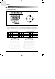
7-3. Circuit Description
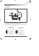
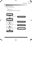
7-3-1. Indoor Fan Control
Circuit Description
■
Use SSR(Solid State Relay) of Micom to change the ON Time until the 220V sine wave equals the fan motor rpm to control. In the
meantime, the Zero Crossing part will recognize AC220V as 0V to determine the Switching Timing.
As the Fan Control Port of Micom detects the "High" signal and the signal turns into "Low" past TR-Array(UL2003), the LED of SSR
obtains 12V, the same input wave with "2" and the Gate of Photo Triac obtains the operating voltage at the same time to determine
the time to turn on SSR. Now the indoor fan motor can operate at the desired rpm.
ZERO CROSSING PARTS
Voltage
Current
Voltage
Current
High RPM Low RPM
DB98_16444A(1)_2 2/9/04 10:05 AM Page 73