AS07AS(6)MA SM_E_15774 2/14/04 2:47 PM Page 47 SERVICE Manual SPLIT TYPE AIR CONDITIONER E DB98-15774A(2) Indoor Unit Outdoor Unit AS07A5(6)MA AS09A5(6)MAF AS12AA(B)MCF US07A5(6)MA US09A5(6)MAF US12AA(B)MCF
AS07AS(6)MA SM_E_15774 2/12/04 9:18 PM Page 2 Safety Precautions The following safety precautions must be taken when using your air conditioner. WARNING INSTALLING THE UNIT Risk of electric shock. • Can cause injury or death. • Disconnect all remote electric power supplies before servicing, installing or cleaning. • This must be done by the manufacturer or its service agent or a similar qualified person in order to avoid a hazard. ◆ The unit should not be installed by the user.
AS07AS(6)MA SM_E_15774 2/12/04 9:18 PM Ι Page 3 Contents DISASSEMBLE AND REASSEMBLE 1. Indoor unit 2. Outdoor unit ΙΙ SET UP THE OPTION CODE ΙΙΙ 4 6 10 TROUBLESHOOTING ΙΛ Λ ΛΙ ΛΙΙ ΛΙΙΙ 1. Items to be checked first 2. Abnormal diagnosis by symptom 13 14 ASSEMBLY DRAWING AND PART’S LIST 1. Indoor unit 2. Outdoor unit 3. Assembly control in 4. Assembly control out 22 24 28 29 REFRIGERATING CYCLE BLOCK DIAGRAM 31 PERFORMANCE CURVE 32 WIRING DIAGRAMS 1. Indoor unit 2.
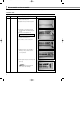
AS07AS(6)MA SM_E_15774 2/12/04 9:18 PM Page 4 Ι Disassemble and reassemble Stop operation of the air conditioner and remove the power cable before repairing the unit. 1 Indoor unit If you disassemble the heat exchanger, you must pump down at first. No. Part Procedure 1 Front Panel 1) Stop the operation of the air conditioner and block the main power. 2) Separate the tape from the front panel. 3) Contract the second finger to the left, and right handle. And pull the inlet grille to open.
AS07AS(6)MA SM_E_15774 2/12/04 9:19 PM Page 5 No. Part Procedure 2 Electrical Parts (Main PCB) 1) Take all the connector of PCB on the upper part. (Included Power cord) Remark 2) Separate the outdoor unit connection wire from the terminal block. 3) If you pull out the main PCB up, it will be taken out. 3 Assembly Tray Drain 1) Separate the drain hose from the extension drain hose. 2) Pull tray drain out from the back body. 4 Heat Exchanger 1) Loosen two ground screws at the right side.
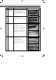
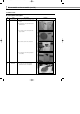
AS07AS(6)MA SM_E_15774 2/12/04 9:19 PM Page 6 Ι Disassemble and reassemble (cont’d) 2 Outdoor unit ■ US07A5(6)MA/US09A5(6)MAF No. 1 Part Common Work Procedure 1) Loosen screws and separate the cover E-part. 2) Separate the connection wire from the terminal block. 3) Loosen five screws and separate the upper cabinet. 4) Loosen the screw of the control box. 5) Loosen nine screws and separate the side cabinet. 2 6 Fan Motor 1) Loosen four screws and separate Guard Fan from the front cabinet.
AS07AS(6)MA SM_E_15774 No. 2/17/04 4:38 PM Part Page 7 Procedure Remark 2) Remove the nut flange (Turn to the clockwise). 3) Separate the fan. 4) Loosen four screws to separate the motor. 3 Heat Exchanger 1) Release the refrigerant. 2) Loosen two screws of left and right side. 3) Disassemble the inlet and outlet pipe by welding. 4) Separate the heat exchanger. 4 Compressor 1) Release the refrigerant. 2) Loosen the nut on the terminal cover and open the terminal cover.
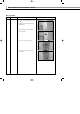
AS07AS(6)MA SM_E_15774 2/12/04 9:19 PM Page 8 Ι Disassemble and reassemble (cont’d) ■ US12AA(B)MCF No. Part 1 Common Work Procedure 1) Loosen a screw and separate the cover E-part. 2) Separate the connection wire from the terminal block. 3) Loosen thirteen screws and separate the front cabinet. 4) Loosen a screw of the control box. 5) Loosen four screws and separate the side cabinet.
AS07AS(6)MA SM_E_15774 2/17/04 4:38 PM No. Part 2 Fan and Motor Page 9 Procedure Remark 1) Remove the nut flange (Turn to the clockwise). 2) Separate the fan. 3) Loosen four screws to separate the motor. 4) Loosen five screws and separate the motor bracket from the base. 3 Heat Exchanger 1) Release the refrigerant. 2) Loosen screws of left and right side. 3) Disassemble the inlet and outlet pipe by welding. 4) Separate the heat exchanger. 4 Compressor 1) Release the refrigerant.
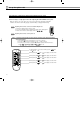
AS07AS(6)MA SM_E_15774 2/12/04 9:19 PM Page 10 ΙΙ Set up the option code The method for setting up the model option with the remote control ◆ It is necessary to set up option codes after replacing the main PCB with service parts. Make sure that you can set up option codes of the remote control after replacing the main PBA. Otherwise, the unit won’t be working properly and all LED lamps on display will be flickering. Step 1 Preparing for the remote control to the main PCB option set. 1.
AS07AS(6)MA SM_E_15774 2/12/04 9:19 PM Page 11 7) If the first number is , it is correct. Otherwise, press the until appears. Step 3 button 8) When pressing the button ~ on the display, select one of them. 9) When pressing the button ~ on the display, select one of them. 10) When pressing the button ~ on the display, select one of them. 11) When pressing the button ~ on the display, select one of them. 12) When pressing the button ~ on the display, select one of them.
AS07AS(6)MA SM_E_15774 2/12/04 9:19 PM Page 12 ΙΙ Set up the option code (cont’d) A table of the option code 12 Model Option code AS07A5MA 010000-1700b7 AS07A6MA 000000-1700b7 AS09A5MAF 010000-1700Fb AS09A6MAF 000000-1700Fb AS12AAMCF 010000-170340 AS12ABMCF 000000-170340
AS07AS(6)MA SM_E_15774 2/12/04 9:19 PM Page 13 ΙΙΙ Troubleshooting 1 Items to be checked first 1) The input voltage should be voltage rating within ±10% range. The air conditioner may not operate properly if the voltage is out of this range. 2) Is the connection cable linking the indoor unit and the outdoor unit properly? The indoor unit and the outdoor unit shall be linked by five cables. Check the terminals if the indoor unit and outdoor unit are properly linked by the same number of cables.
AS07AS(6)MA SM_E_15774 2/12/04 9:19 PM Page 14 ΙΙΙ Troubleshooting (cont’d) 2 Abnormal diagnosis by symptom 1. No Power - Initial diagnosis 1) Checklist : (1) Is input voltage normal? (2) Is AC power linked correctly? (3) Is output voltage of DC regulator IC KA78L05 (IC02) normal? (4.5VDC-5.5VDC) 2) Troubleshooting procedure Remove the power cord and plug in again in approx.
AS07AS(6)MA SM_E_15774 2/12/04 9:19 PM Page 15 1-1 No Power-Initial diagnosis in case of the Outdoor Unit PCB of US12AA(B)MCF 1) Checklist : (1) Is AC voltage between “L1” and “1” of outdoor terminal block is normal? (Input voltage within ±10% range) If the Output is not checked, check “L1” and “1” of Indoor Terminal Block.
AS07AS(6)MA SM_E_15774 2/12/04 9:19 PM Page 16 ΙΙΙ Troubleshooting (cont’d) 2.
AS07AS(6)MA SM_E_15774 2/12/04 9:19 PM Page 17 3.
AS07AS(6)MA SM_E_15774 2/12/04 9:19 PM Page 18 ΙΙΙ Troubleshooting (cont’d) 3-2 US12AA(B)MCF 1) Checklist : (1) Is LED 01(GRN) on? (2) Are all connectors linked correctly? 2) Troubleshooting procedure Check the power supply between “L1” and “L2” of the outdoor terminal block Is voltage rating between “L1” and “1” ? NO Check the indoor PCB again YES Is LED 01 of the indoor PCB on? NO Check the connection wire and No Power Refer to page 14 YES Is the compressor on? NO Check the compressor lead
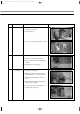
AS07AS(6)MA SM_E_15774 2/12/04 9:19 PM Page 19 4. When the UP/DOWN Louver Motor Does Not Operate - Initial Diagnosis 1) Checklist : (1) Is input voltage normal? (2) Is the UP/DOWN louver motor properly connected with the connector (CN61)? 2) Troubleshooting procedure Remove the power cord and plug it in again in approx. five seconds Does STD lamp blink? NO YES Does it start operating when you push the swing button of the remote control? Check as the procedure "No Power".
AS07AS(6)MA SM_E_15774 2/12/04 9:19 PM Page 20 ΙΙΙ Troubleshooting (cont’d) 5. When there is no cool air in the current mode 1) Checklist : (1) Is the set temperature of the remote control lower than room temperature in the Cool mode? (2) Is the Indoor PCB properly connected with the CN71 connector? 2) Troubleshooting procedure After training on, the Cooling starts operating in five minutes. YES Normal NO Is #9 of Micom (IC04) DC 5.0 V? NO Micom is abnormal.
AS07AS(6)MA SM_E_15774 2/12/04 9:19 PM Page 21 6. When the remote control does not operate 1) Troubleshooting procedure Remove the power cord and plug it in again approx. five Seconds Does STD lamp blink? NO YES The melody sounds from the indoor unit when you push the On/Off button on the remote control. YES Check as the procedure “No Power” Refer to page14 Normal NO Is voltage of battery less than 2.
AS07AS(6)MA SM_E_15774 2/12/04 9:19 PM Page 22 ΙΛ Assembly drawing and part’s list 1 Indoor unit 18 18-6 18-6-1 18-1 18-4 18-5 18-3 24 16 18-2 17 13 13-2 13-4 13-3 13-1 14 15 11 12 10 8 20 25 22 23 19 9 6 5 7 4 21 3 2 1 22
AS07AS(6)MA SM_E_15774 ■ 2/12/04 9:19 PM Page 23 Part’s List No. Code No.
AS07AS(6)MA SM_E_15774 2/12/04 9:19 PM Page 24 ΙΛ Assembly drawing and part’s list (cont’d) 2 Outdoor unit ■ US07A5(6)MA/US09A5(6)MAF 22 23 20 21 7 17 6 8 9 -1 12 4 5 24 2 18 19 3 8- 1 -1 10 16 2 8- 3 17 13 15 11 14 4 8- 1 8- 18
AS07AS(6)MA SM_E_15774 ■ 2/12/04 9:19 PM Page 25 Part’s List Q’TY No. Code No.
AS07AS(6)MA SM_E_15774 2/12/04 9:19 PM Page 26 ΙΛ 24 Assembly drawing and part’s list (cont’d) 25 1 21 5 12 0 2 3 6 4 1 8 7 8- 4 8- 8- 9 7 13 8- 14 8 8 -1 8- 8- 12 3 8- 14 8- 2 8- 8- 11 8- 13 8- 6 15 9 8- 5 16 23 17 10 11 19 18 22 20 ■ US12AA(B)MCF 26
AS07AS(6)MA SM_E_15774 ■ 2/12/04 9:19 PM Page 27 Part’s List No. Code No. Description Specification 1 DB63-00385B GUARD FAN HSWR,OD 2.
AS07AS(6)MA SM_E_15774 2/12/04 9:19 PM Page 28 ΙΛ Assembly drawing and part’s list (cont’d) 3 Assembly control in ■ AS07A5(6)MA/AS09A5(6)MAF/AS12AA(B)MCF ■ Part’s List No. Description 1 HOLDER CONTROL ASS’Y MAIN PCB ASS’Y TERMINAL BLOCK ASS’Y DISPLAY PCB CONNECTOR WIRE PCB U/D SCREW HOLDER CLAMP IN SEAL - PANEL FRONT RH SEAL - H/CONTROL FRONT LABEL ASS’Y THERMISTOR 2 3 4 5 6 7 8 9 10 11 28 Code No.
AS07AS(6)MA SM_E_15774 2/12/04 9:19 PM Page 29 4 Assembly control out ■ US12AA(B)MCF 29
AS07AS(6)MA SM_E_15774 2/12/04 9:19 PM Page 30 ΙΛ Assembly drawing and part’s list (cont’d) 4 Assembly control out (cont’d) ■ 30 Part’s List No. Description Specification Remark 1 PLATE-CONTROL OUT SGCC-M T0.6 - 3 C-OIL (CAPACITOR) 35uF/450VAC - 4 CLIP-CAPACITOR SGCC-MØ50 - 5 SCREW-TAPPING 2S-M4 x L10 SNA 6 C-OIL(CAPACITOR) 1.
AS07AS(6)MA SM_E_15774 2/12/04 9:19 PM Page 31 Λ Refrigerating cycle block diagram Indoor unit Outdoor unit Capillary tube T1 2-way valve Heat exchanger (Evaporator) Propeller fan Cross fan Liquid side Heat exchanger (Condenser) T2 Gas side 3-way valve Cooling Compressor Gas leak check point Refrigerating cycle temperature and pressure STD Pressure Operating Condition Use Temp. Condition [°F(°C )] Outdoor Indoor (psi) 3-Way Valve Cooling Piping Temp.
AS07AS(6)MA SM_E_15774 2/12/04 9:19 PM Page 32 ΛΙ Performance curve ■ AS07A5(6)MA N o t e Data is based on condition of indoor humidity 50%. Air flow should be set at HI. Total power consumption Total power consumption (x10 3kW) 1.0 71 67 63 59 0.9 Indoor intake air WB temperature(°F) 0.8 0.7 0.6 0.5 0.
2/12/04 9:19 PM Page 33 High pressure Condensing pressure (psi.G) 390 86 80 75 70 340 Indoor DB temperature(°F) 290 240 190 140 55 65 75 85 95 105 115 Outdoor ambient DB temperature(°F) Low pressure 90 85 Suction pressure (psi.
AS07AS(6)MA SM_E_15774 2/12/04 9:19 PM Page 34 ΛΙ Performance curve (cont’d) Suction temperature 80 Suction temperature (°F) 70 86 60 80 50 75 70 40 30 Indoor DB temperature (°F) 20 10 0 55 65 75 85 95 105 115 Outdoor ambient DB temperature (°F) Discharge temperature Discharge temperature (°F) 240 86 80 75 70 220 200 180 Indoor DB temperature(°F) 160 140 120 100 55 65 75 85 95 Outdoor ambient DB temperature (°F) 34 105 115
AS07AS(6)MA SM_E_15774 2/12/04 9:19 PM Page 35 ■ AS09A5(6)MAF N o t e Data is based on condition of indoor humidity 50%. Air flow should be set at HI. Total power consumption Total power consumption (x10 3kW) 1.3 71 67 63 59 1.2 1.1 Indoor intake air WB temperature(°F) 1.0 0.9 0.8 0.7 0.
AS07AS(6)MA SM_E_15774 2/12/04 9:19 PM Page 36 ΛΙ Performance curve (cont’d) High pressure Condensing pressure (psi.G) 390 86 80 75 70 340 Indoor DB temperature(°F) 290 240 190 140 55 65 75 85 95 105 115 Outdoor ambient DB temperature(°F) Low pressure 90 Suction pressure (psi.
2/12/04 9:19 PM Page 37 Suction temperature 80 Suction temperature (°F) 70 86 60 80 50 75 70 40 30 Indoor DB temperature(°F) 20 10 0 55 65 75 85 95 105 115 Outdoor ambient DB temperature (°F) Discharge temperature 240 Discharge temperature (°F) AS07AS(6)MA SM_E_15774 86 80 75 70 220 200 180 Indoor DB temperature(°F) 160 140 120 100 55 65 75 85 95 105 115 Outdoor ambient DB temperature (°F) 37
AS07AS(6)MA SM_E_15774 2/12/04 9:19 PM Page 38 ΛΙ Performance curve (cont’d) ■ AS12AA(B)MCF N o t e Changes in the dotted box are caused by the RPM change of outdoor fan. Total power consumption Total power consumption (x10 3kW) 1.5 71 67 63 59 1.4 1.3 Indoor intake air WB temperature(°F) 1.2 1.1 1.0 0.
2/12/04 9:19 PM Page 39 High pressure Condensing pressure (psi.G) 350 86 80 75 70 330 310 290 Indoor DB temperature(°F) 270 250 230 210 190 170 55 65 75 85 95 105 115 Outdoor ambient DB temperature(°F) Low pressure 100 95 Suction pressure (psi.
AS07AS(6)MA SM_E_15774 2/12/04 9:19 PM Page 40 ΛΙ Performance curve (cont’d) Suction temperature 80 Suction temperature (°F) 70 86 60 80 50 75 40 70 30 Indoor DB temperature(°F) 20 10 0 55 65 75 85 95 105 115 Outdoor ambient DB temperature(°F) Discharge temperature 230 Discharge temperature (°F) 220 210 86 80 75 70 Indoor DB temperature(°F) 200 190 180 170 160 150 140 55 65 75 85 95 Outdoor ambient DB temperature(°F) 40 105 115
AS07AS(6)MA SM_E_15774 2/12/04 9:22 PM Page 41 ΛΙΙ Wiring diagrams 1 Indoor unit ■ AS07A5(6)MA/AS09A5(6)MAF/AS12AA(B)MCF This document can not be used without Samsung’s authorization.
AS07AS(6)MA SM_E_15774 2/12/04 9:22 PM Page 42 ΛΙΙ Wiring diagrams (cont’d) 2 Outdoor unit ■ US07A5(6)MA/US09A5(6)MAF DIAGRAM This document can not be used without Samsung’s authorization.
AS07AS(6)MA SM_E_15774 2/12/04 9:24 PM Page 43 ■ US12AA(B)MCF DIAGRAM Motor capacitor : 1.5µF x 450VAC Comp capacitor : 35µF x 450VAC This document can not be used without Samsung’s authorization.
AS07AS(6)MA SM_E_15774 2/12/04 9:40 PM Page 44 ΛΙΙΙ Schematic diagrams 1 Indoor unit ■ AS07A5(6)MA/AS09A5(6)MAF/AS12AA(B)MCF CR71 Model Input Voltage 4uF/300V AS07A5(6)MA/AS09A5(6)MAF 115V/60Hz 1.2uF/450V AS12AA(B)MCF 208V~230V/60Hz This document can not be used without Samsung’s authorization.
AS07AS(6)MA SM_E_15774 2/12/04 9:48 PM Page 45 2 Outdoor unit ■ US12AA(B)MCF This document can not be used without Samsung’s authorization.
AS07AS(6)MA SM_E_15774 2/12/04 9:24 PM Page 46 ELECTRONICS This Service Manual is a property of Samsung Electronics Co.,Ltd. Any unauthorized use of Manual can be punished under applicable lnternational and/or domestic law.