4 Channel Digital Video Image Recorder (DVR) CA7 Installation and Operating Instructions These instructions should be retained in a safe place for future reference.
CONTENTS 1 INTRODUCTION 2 KIT CONTENTS 3 4 6.5.3 Password Setup 21 6.5.4 Clear Account Info 21 6.5.5 Keypad Tone 21 6.5.6 Time Set 22 6.5.7 Event List (Playback Feature) 22 3 DVR FEATURES 5 4 PHYSICAL UNIT 6 6.6 Language 23 6.7 Logout 23 6.8 Exit 23 4.1 Front Panel 4.1.1 DVR Button Functions 6 6 4.2 Rear Panel 8 5 HARDWARE SETUP 9 5.1 Hard Disk Drive Installation 9 5.2 Monitor Connection 9 5.3 Camera(s) Connection 9 5.4 Mouse Connection 10 5.
INTRODUCTION Section 1 The Response 4 Channel DVR provides a total video security solution for 4 channel digital surveillance supporting duplex (simultaneous playback and record) functionality. The DVR’s front panel buttons or mouse can operate all DVR menu settings. Please read before you start: Always use discretion when installing CCTV surveillance equipment especially when there is perceived policy.
KIT CONTENTS Section 2 1 x 4 Channel DVR unit (with a 160GB hard drive unit fitted in the drawer) 1 x Power adaptor and power cord 1 x Video output to monitor cable (1m) 2 x BNC to RCA adaptors 1 x Optical mouse 1 x User manual 1 x PC driver CD for PC back up (for Windows based operating systems only including Vista) Keys for the hard drive drawer What you need to purchase: USB memory stick if you require backing up recorded video on to a PC. (See appendix for the only compatible USB stick models).
DVR FEATURES Section 3 ● True duplex functionality: simultaneous play / record ● PAL / NTSC operation ● 160GB installed hard drive unit ● High quality colour Video at 50fps or 60fps recording / playback ● Recording speed: PAL max. 50fps (quad); NTSC max. 60fps (quad) ● Recording mode: continuous, motion detection, time schedule ● 123 hours continuous recording at 25fps with the 160GB hard drive.
PHYSICAL UNIT Section 4 4.1 Front Panel Channel Buttons 1-4 Hard Drive Drawer CH1 REW CH1 PAUSE CH1 PLAY Quad Button CH1 FWD QUAD STOP UP MENU SEL ESC EDIT REC DOWN PWR Hard Drive Drawer Lock ● LED Lights HDD Rewind, Pause, Play, Forward, Stop and Record Buttons Up/Down, SEL Menu, ESC and EDIT Buttons LED Lights: (a) GREEN (PWR): The DVR unit is powered up and running. (b) RED (HDD): ● System is recording or in playback mode. Hard Drive Drawer Lock 4.1.
– Quad Use this button for full screen display of all 4 video channels on the monitor screen. If you push this button, the DVR will display all 4 channels (cameras) at the same time in quad screen. – ● (REC) Press “REC” button to start manual recording. You will then see a red dot ‘ ● ’ on the selected channel on the screen, which means that the channel is now recording. To stop manual recording, press “REC” again during recording mode. – ■ (STOP) To stop playback, press the “STOP” button.
– UP / DOWN To change the menu field, use the up “ ” or down “ ” buttons. – SEL Use this button to change values on main menu or sub menu setting. Also use this button to increase values when adjusting parameters. 4.2 Rear Panel AC-DC Power Adaptor Jack Vent for Internal Cooling Fan PS/2 VIDEO OUTPUT Video Output ● CH1 CH2 CH3 CH4 Video Input - Channels 1-4 DC12V PS/2 Mouse Port USB Port USB PORT Use this port to backup video on to a USB stick for transferring on to a PC.
HARDWARE SETUP Section 5 5.1 Hard Disk Drive Installation Note: Only read if you wish to replace / upgrade the existing supplied 160GB hard drive unit fitted in the DVR. 1. Unlock the front hard drive drawer using the key supplied. 2. Pull the drawers lever to remove the drawer from the DVR. 3. Remove the x 4 screws on the base of the drawer which secure the hard drive in place to remove the existing unit. 4. Replace with the new hard drive unit, refit and lock the drawer again. 5.
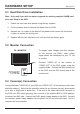
"VIDEO IN" on DVR "VIDEO OUT" on Camera VIDEO INPUT CH1 Camera Power Supply Adaptor CH2 CH3 CH4 DVRs Power Supply Adaptor Video output from Camera to DVR Note: If this DVR is used with the Wireless Colour Camera CCTV Kit (CWFK1), the video output from the receiver can be connected to either channel 1, channel 2, channel 3 or channel 4, to view the wireless camera. 5.4 Mouse Connection Connect the PS/2 mouse to the port shown on the DVR.
SETUP Section 6 If you have just replaced the existing hard drive with a new hard drive on the system, it is advised to format the hard drive first. Please refer to Section 6.5, pages 18- 19. The system includes a login window, and there are three password levels in the system, including admin (highest), operator, and guest (lowest), Fig. 6.01. Fig. 6.01 If the user does not login to the system, the user can only view live video display.
B: Set up using the Mouse After the system has booted-up, click the right mouse button and the login window will appear. Move the cursor to “Account”, and click the left mouse button and input the correct account by moving the cursor over the correct numbers/characters and left clicking the mouse button to select them. Select “Password” and input the correct password. Finally select “Login” to Fig. 6.02 enter the system.
6.1 Camera Use this option for video colour adjustment for each channel (1, 2, 3, 4). Move to the “Display” option to enable or disable the screen display of each camera. Modify the camera name of each channel (Figs. 6.04 and 6.05). Fig. 6.04 Fig. 6.05 6.2 Record This section allows the user to set the DVR to record over timed periods and via motion detection. (Note: If at any time you wish to start manually recording then press the “REC ● ” button once on the DVR.
6.2.1 [RECORD FRAMERATE] Change the record frame rate for each channel - see Fig. 6.07. The higher the record frame rate, the more natural movement you will see in playback. Independent setting for each channel is possible. For PAL video output format, the system Fig. 6.07 default value is 12 frames per second with each channel, which means the system will record 48 frames per second with all channels. The user can set frame rate as 3 ~ 25 frames per second with each channel.
period. The user can select the same record method for the whole 24 hr period in one go. Move the cursor to 24 and press [QUAD] button in the DVR front panel, or left click the mouse button on the time period 24. Grey bar Red bar Green bar Fig. 6.08 - Grey bar: No recording will be made for this time period unless the user activates manual recording. - Red bar: The time period with a red bar will activate continuous recording mode (Time record) unless there is any manual stopping during that period.
6.3.2 [EVENT REC DURATION] This sets the recording duration (in seconds) after motion recording is activated. Selection values are “ 05, 10, 15, 20, 25, 30 ” (in seconds). 6.3.3 [MOTION DETECTION] [CHANNEL] Select the channel (1, 2, 3, 4) for recording by motion detection (Fig. 6.10). [SENSITIVITY] This adjusts the sensitivity of the built-in motion sensor on the DVR system while recording. The lower the number, Fig. 6.10 the higher the sensitivity is. Values are “1, 2, 3, 4, Off ”.
[MOTION AREA] Note: To start Motion Record, the user must complete the “Motion Area” setup. Use this option to select the range of motion detection area. Use the DVR’s front panel buttons or mouse click to assign the area. The front panel and mouse control instructions are below. [Using the front panel buttons] Press [SEL] once to pitch on the area, press [SEL] twice to cancel the area.
6.4.3 [VIDEO ADJUSTMENT] You can move the entire video screen up, down, left and right using this option. Keypad assignment on the front panel is below. – CH1 for up, CH2 for down, CH3 for left, CH4 for right. Mouse function is below: Click the right mouse button and the following icons will appear: . Click the left button to select each icon. “ ” for up, “ ” for down, “ ” for left, “ ” for right, “ ” for ESC. 6.
6.5.1 Hard Disk Setup [OVERWRITE ENABLED] If you select Yes, then recording continues and overwrites the previous recording when the hard disk drive space is full. If you select No, then recording stops when the hard disk drive is full. It won’t record until “overwrite enable” is “Yes” (Fig. 6.14). Fig. 6.14 [FORMATING THE HARD DISC DRIVE] If you format the hard drive, all the video data stored on the hard drive will be deleted.
6.5.2 Account Setup Log into the main menu (see 6. SETUP). Move the cursor down to ‘System’ and press [SEL] button or click the left mouse button to select. In the system menu select ‘Account’ and the following screen will appear. Once the user is logged into the system at admin level, the Account Setup allows the administrator to add new users, delete existing ones and modify the user’s name / password / and level. The system allows up to 4 user accounts.
6.5.3 Password Setup The default password is 111111. All numbers, letters and symbols in the box can be used to set the password (Fig. 6.22). Press [SEL ] to input values, and move the prompt to the option of “Enter”, press [SEL ] to input current password. Fig. 6.22 Button function on the front panel: – CH1 for up, CH2 for down, CH3 for left, CH4 for right. The same operation measure can be used to input the new password and confirm. When the password change has Fig. 6.
6.5.6 Time Set You can adjust the current time, date and year at any time by region. Set your region first and then set the current time so that the video back-up data can be played without time shifting later on. Fig. 6.25 Date and Time format as below: *** 2008 / 08 / 08 – year / month / day *** 01:01:00 – hour: minute: second To move the cursor on the screen, use the “UP” and “DOWN” key on the DVR front panel and then press the [SEL] button to change the numeric value.
To playback by Event list, using the [UP] / [DOWN] or channel number (CH3 for Page Up or CH4 for Page Down) key on the front panel, select the event that you want to playback and press the [PLAY] button. Another way is to move the mouse up or down and click the left mouse button (“ ” for Page Up or “ ” for Page Down), select the event that you want to playback and double click the left mouse button. This will playback the recorded video data. 6.6 Language The system supports multi-language OSD.
PLAYBACK WITH TIME SEARCH FUNCTION Section 7 This is an enhanced playback option, which enables the user to manually adjust to a specific starting time for playback (Fig 7.01). Fig. 7.01 Front Panel Control: In order to playback with time search function, press the [PLAY] button on the front panel first. Press the [SEL] button to change the value of the playback start date & time and press the [PLAY] button again. Playback will start from the date & time indicated by the user.
BACKUP VIA USB MEMORY STICK Section 8 Note: The USB memory stick is not supplied with this kit. Please purchase only the listed USB models in the Appendix section (11.1) as only they are compatible with this DVR. The DVR system has an enhanced back-up feature so that it’s possible to transfer the video data image recorded on the hard drive to a USB memory stick. You must format the USB stick to a ‘FAT32’ File system from a PC first. This can be done as follows: 1.
Fig. 8.02 Fig. 8.03 Select “Start” on the screen to begin the back up process (Figs. 8.02 to 8.04). Fig. 8.04 It will take a few minutes to write the video data to the USB memory stick. The file size number displayed will grow until it’s completed with the message below: WRITING… Then it will show the following message on the screen: FIXATING… Remove the USB stick and attach it into your PC once transfer is completed. Select “Exit” to continue using the DVR.
RECORDING LENGTH Section 9 Video system is “PAL”. Estimate recording time basing on a 160GB hard drive. The best record quality is 3, and the lowest record quality is 1. Record Speed 50F/sec 25F/sec REC Quality DATA RATE (GB/Hour) Record Time (Hour) 3 4.4 36 2 2.8 57 1 2.3 69 3 2.4 66 2 1.6 100 1 1.
PLAYBACK WITH BACKED-UP VIDEO DATA ON PC Section 10 10.1 Software Installation The PC backup CD provided is only compatible with Windows based operating systems including Vista. 1. Insert the Driver Program CD in your CD-ROM. 2. Install by setup. (Fig. 10.01). 3. Set up the install directory. (Fig. 10.02). 4. Execute: Start >Program> Vx 4SLPlayer. Fig. 10.01 Fig. 10.02 10.2 Program Interface Double click the left mouse button on the icon “ ” if located on the desktop to run the program.
10.3 Button Functions Fig. 10.04 1. Open File 2. Fast Backward 3. Play Reverse 4. Previous Frame 5. Pause 6. Next Frame 7. Play 8. Fast forward 9. Still Capture 1. 10. Split 1 11. Split 4 12. Volume Scroll Bar 13. Mute On / Off 14. Playing Scroll Bar 15. Minimize the window 16. Close the window Click “ ” to play the video recorder in “ *.VVF” format (Fig. 10.05). Fig. 10.
2. Still Capture. Click “ ” to capture an image from a video. Click the right mouse button to select “Options…” to setup the path for still capture. Click the left mouse button to select the folder that you want. For example select the folder as “E: \ VOC 4CH \ backup”. 3. In the “Options” window, you can setup other menu selection such as “General & On screen display date/time format” (Fig. 10.06). Fig. 10.06 √ Always on top (A): The client window will always display on top of all the windows.
5. Translating the “VVF File Format (*.VVF)” into “AVI File Format (*.AVI)”. After translating to an AVI file, the file can then be played back using software such as Windows Media player or played back on an MP4 player for example. First click the right mouse button to select the option “Export”, and then click the left mouse button to see the window “Export To AVI”. Secondly select the channels you want to export,.
6. Capture. If you want to save part of a VVF file (*.VVF) on your computer rapidly, you must ensure any video playback is paused. Drag the playing scroll bar to select the start time, click the right mouse button to select the option “Capture”, then left click “Mark In”. Drag the playing scroll bar ahead to select the end time, click the right mouse button to select the option “Capture”, then left click “Mark Out”. Last left click “Export” and there will be a window “Capture” on screen.
TROUBLE SHOOTING Section 11 PROBLEM SOLUTION No picture can be viewed The power supply adaptor for the camera(s) or DVR is not plugged in. Check all video cable connectors between the cameras and the DVR. The TV is not tuned to view the correct channel. Poor picture quality Clean the camera lens. Adjust the contrast/brightness on the TV.
APPENDIX Section 12 12.1 Compatible USB Memory Sticks with the DVR Note that only the following USB devices are compatible with this DVR model.
12.2 Specification ITEM 4 CHANNEL DVR Video format PAL / NTSC Operation system Linux Video input 4 channel composite BNC Video output 1 channel composite BNC Display speed PAL: NTSC: 100fps (4 x 25fps) 120fps (4 x 30fps) Display resolution PAL: NTSC: 704 x 576 704 x 480 Recording resolution PAL: NTSC: 640 x 272, 320 x 136 640 x 224, 320 x 112 Recording speed PAL: Max. 50 frame per second; 3fps ~ max 25fps (each channel) adjustable NTSC: Max. 60 frame per second; 3fps ~ max.
ACCESSORIES IN THE RANGE Section 13 There are a range of accessories available in the Response CCTV product range to expand your system: CWK1 Wired Colour Camera CCTV Kit CA1 2 Channel Digital Video Image Recorder CA2 LCD Screen for Wireless / Wired CCTV Kits CWFK1 Wireless Colour Camera CCTV Kit CA3 Wireless Colour Accessory Camera (requires CWFK1 CCTV KIT to operate) CA5 Professional Heavy Duty Camera CCTV Kit CA6 Dummy Professional Heavy Duty Camera CA8 Wired Internal Colour Dome Camera
DISPOSAL – RECYCLING INSTRUCTIONS Directive (2002/96/EC) This product is classified by the Waste Electrical or Electronic Equipment (WEEE) Directive. It should not be disposed of with other household or commercial waste. At the end of its useful life the packaging and product should be disposed of via a suitable recycling centre. For information on available facilities, please contact your local authority or the retailer from where the product was purchased.
GUARANTEE Section 15 Novar ED&S undertakes to replace or repair at its discretion goods (excluding non rechargeable batteries) should they become defective within 1 year solely as a result of faulty materials and workmanship. If the product has not been installed, operated or maintained in accordance with the instructions, has not been used appropriately or if any attempt has been made to rectify, dismantle or alter the product in any way the guarantee will be invalidated.
Novar Electrical Devices and Systems Limited. (A Honeywell Company) The Arnold Centre, Paycocke Road, Basildon, Essex SS14 3EA. UK www.friedland.co.uk © Novar Electrical Devices and Systems Limited. 2009 50043907 Rev.