General Multilayer Ceramic Capacitors MLCC is an electronic part that temporarily stores an electrical charge and the most prevalent type of capacitor today.
3 CAPACITANCE TEMPERATURE CHARACTERISTIC ● Code Temperature Temperature Characteristics Range C COG C△ 0±30(ppm/ ℃) P P2H P△ -150±60 R R2H R△ -220±60 S2H S△ -330±60 T T2H T△ -470±60 U U2J U△ -750±60 L S2L S△ +350 ~ -1000 A X5R X5R ±15% -55 ~ +85℃ X7R X7R ±15% -55 ~ +125℃ X X6S X6S ±22% -55 ~ +105℃ F Y5V Y5V +22 ~ -82% -30 ~ +85℃ Class Ⅰ S B Class Ⅱ -55 ~ +125℃ Temperature Characteristics Below 2.0pF 2.2 ~ 3.9pF Above 4.
5 CAPACITANCE TOLERANCE ● Code Tolerance A ±0.05pF B ±0.1pF C ±0.25pF D ±0.5pF F ±1pF F ±1% G ±2% J ±5% K ±10% M ±20% Z +80, -20% Nominal Capacitance Less than 10pF (Including 10pF) More than 10pF Code Rated Voltage Code Rated Voltage R 4.0V D 200V Q 6.
7 THICKNESS OPTION ● Size Code Thickness(T) 0201(0603) 3 0402(1005) 0603(1608) 0805(2012) 1206(3216) Code Thickness(T) 0.30±0.03 F 1.25±0.20 5 0.50±0.05 H 1.6±0.20 8 0.80±0.10 I 2.0±0.20 A 0.65±0.10 J 2.5±0.20 C 0.85±0.10 L 3.2±0.30 F 1.25±0.10 F 1.25±0.20 Q 1.25±0.15 H 1.6±0.20 Y 1.25±0.20 I 2.0±0.20 C 0.85±0.15 J 2.5±0.20 F 1.25±0.15 L 3.2±0.30 H 1.6±0.20 F 1.25±0.20 H 1.6±0.20 I 2.0±0.20 J 2.5±0.20 V 2.5±0.
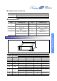
10 RESERVED FOR FUTURE USE ● 6 Code Description of the code N Reserved for future use 11 PACKAGING TYPE ● Code Packaging Type Code Packaging Type B Bulk F Embossing 13" (10,000EA) P Bulk Case L Paper 13" (15,000EA) C Paper 7" O Paper 10" D Paper 13" (10,000EA) S Embossing 10" E Embossing 7" General Capacitors APPEARANCE AND DIMENSION L T W BW CODE DIMENSION ( mm ) EIA CODE L W T (MAX) BW 03 0201 0.6 ± 0.03 0.3 ± 0.03 0.33 0.15 ± 0.05 05 0402 1.0 ± 0.05 0.
RELIABILTY TEST CONDITION NO ITEM 1 App earance PERFORMA NCE TEST CONDIT ION No Abnormal Exterior Appeara nce Thro ugh Micr osco pe(×10) 1 0,0 00㏁ or 500㏁·㎌ which ever is sma ller Insu lation 2 Resistance Apply the Ra ted Voltage Fo r 6 0 ~ 120 Sec.
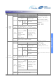
RELIABILTY TEST CONDITION NO ITEM PERFORMANCE TEST CONDITION Capacitance shall be measured by the steps Characteristics Temp. Coefficient (PPM/℃) Ⅰ Step 0 ± 30 1 PH -150 ± 60 2 RH -220 ± 60 SH -330 ± 60 TH -470 ± 60 C0G Class shown in the following table. UL -750 ± 120 SL +350 ~ -1000 Temp.(℃) 25 ± 2 Min. operating temp. ± 2 25 ± 2 3 Max. operating temp ± 2 4 25 ± 2 5 (1) Class Ⅰ Temperature Coefficient shall be calculated from Temperature 7 the formula as below.
RELIABILTY TEST CONDITION NO ITEM PERFORMANCE More Than 75% of the terminal surface is to be soldered newly, So metal part does not come out or dissolve 10 TEST CONDITION Solder Solder Temp. Solder ability Sn-3Ag-0.5Cu 63Sn-37Pb 245±5℃ 235±5℃ Flux Dip Time Pre-heating Apperance No mechanical damage shall occur. Characteristics Capacitance Change Within ±2.5% or Class Ⅰ ±0.25㎊ whichever is RMA Type 3±0.3 sec. 5±0.5 sec. at 80~120℃ for 10~30 sec.
RELIABILTY TEST CONDITION NO ITEM PERFORMANCE Appearance TEST CONDIT ION No mechanical damage shall occur. Characteristics Within ±5.0% or Class Ⅰ Capacitance Temperature Capacitance Change ±0.5㎊ : 40±2 ℃ Relative humidity : 90~95 %RH Duration time : 500 +12/-0 hr. whichever is larger Leave the capacitor in ambient A(X5R)/ Class B(X7R)/ Ⅱ X(X6S) condition for specified time* before Within ±12.5% measurement. CLASSⅠ : 24±2 Hr.
RELIABILTY TEST CONDITION NO ITEM PERFORMANCE Appearance No mechanical damage shall occur. TEST CONDITION Applied Voltage : 200%* of the rated voltage Temperature : max. operating temperature Characteristics Within ±3% or ±0.3㎊, Class Ⅰ Whichever is larger A(X5R)/ Capacitance B(X7R) Class Ⅱ Capacitance Change X(X6S) Duration Time : 1000 +48/-0 Hr. Charge/Discharge Current : 50㎃ max. * refer to table(3) : 150%/100% of the rated Within ±12.
RELIABILTY TEST CONDITION Recommended Soldering Method Size Temperature inch (mm) Characteristic 0201 (0603) Condition Capacitance - Flow Reflow - - ○ 0402 (1005) Class I 0603 (1608) Soldering Method 0805 (2012) Class II By Size & Capacitance ○ ○ ○ C ≥ 1㎌ - ○ - ○ ○ ○ ○ C ≥ 4.7㎌ - ○ - - ○ Array Class I 1206 (3216) ○ C < 4.
PACKAGING ● CARDBOARD PAPER TAPE (4mm) Feeding Hole Chip Inserting Hole D E A F B t P0 P2 W P1 unit : mm Sym bol Type B 0603 (1608) 1.1 ±0.2 1.9 ±0.2 0805 (2012) 1.6 ±0.2 2.4 ±0.2 1206 (3216) 2.0 ±0.2 3.6 ±0.2 W F E P1 P2 P0 D t 8.0 ±0.3 3.5 ±0.05 1.75 ±0.1 4.0 ±0.1 2.0 ±0.05 4.0 ±0.1 Φ1.5 +0.1/-0 1.1 Below ● CARDBOARD PAPER TAPE (2mm) Feeding Hole Chip Inserting Hole D E A F B t P0 P2 W P1 unit : mm Sym bol Type D i m e n s i o n 0201 (0603) A B 0.38 ±0.
PACKAGING ● EMBOSSED PLASTIC TAPE F e e d in g H o le C h ip in se r tin g H o le D E A F W B t1 P0 P2 P1 t0 u n it : m m S ym b o l T yp e 0805 (2 0 1 2 ) 1206 (3 2 1 6 ) 1210 (3 2 2 5 ) 1808 (4 5 2 0 ) 1812 (4 5 3 2 ) 2220 (5 7 5 0 ) B 1 .4 5 ± 0.2 1 .9 ± 0.2 2 .9 ± 0.2 2 .3 ± 0.2 3 .6 ± 0.2 5 .5 ± 0.2 2 .3 ± 0 .2 3 .5 ± 0 .2 3 .7 ± 0 .2 4 .9 ± 0 .2 4 .9 ± 0 .2 6 .2 ± 0 .2 W F E 8 .0 ±0 .3 3 .5 ± 0 .0 5 P1 P2 D 5 .6 0 ± 0 .0 5 t1 t0 2.5 m ax 4 .0 ± 0 .1 1 .7 5 ± 0 .1 1 2 .0 ±0 .
PACKAGING ● REEL DIMENSION E C B R D W t unit : mm Symbol 7" Reel 13" Reel A B φ180+0/ -3 φ60+1/ -3 φ330±2.0 φ80+1/ -3 C D E W φ13 ±0.3 25 ±0.5 2.0± 0.5 9 ±1.5 t R 1.2± 0.2 2.2± 0.2 1.
● BULK CASE PACKAGING - Bulk case packaging can reduce the stock space and transportation costs. - The bulk feeding system can increase the productivity. - It can eliminate the components loss. A B T C D E G H L I unit : mm Symbol A B T C D E Dimension 6.8±0.1 8.8±0.1 12±0.1 1.5+0.1/-0 2+0/-0.1 3.0+0.2/-0 Symbol F W G H L I Dimension 31.5+0.2/-0 36+0/-0.2 19±0.35 7±0.35 110±0.7 5±0.
APPLICATION MANUAL ● ELECTRICAL CHARACTERISTICS ▶ CAPACITANCE - TEMPERATURE CHARACTERISTICS % 8 % C C 40 6 20 4 X5R S2L 2 -5 5 -40 -2 0 25 40 60 -6 0 -4 0 25 -2 0 100 125 COG Te m p .
● STORAGE CONDITION ▶ Storage Environment The electrical characteristics of MLCCs were degraded by the environment of high temperature or humidity. Therefore, the MLCCs shall be stored in the ambient temperature and the relative humidity of less than 40℃ and 70%, respectively. Guaranteed storage period is within 6 months from the outgoing date of delivery.
● ADHESIVES When flow soldering the MLCCs, apply the adhesive in accordance with the following conditions. ▶ Requirements for Adhesives They must have enough adhesion, so that, the chips will not fall off or move during the handling of the circuit board. They must maintain their adhesive strength when exposed to soldering temperature. They should not spread or run when applied to the circuit board. They should harden quickly. They should not corrode the circuit board or chip material.
▶ Bending Stress When double-sided circuit boards are used, MLCCs first are mounted and soldered onto one side of the board. When the MLCCs are mounted onto the other side, it is important to support the board as shown in the illustration. If the circuit board is not supported, the crack occur to the ready-installed MLCCs by the bending stress. nozzle force support pin Manual soldering can pose a great risk of creating thermal cracks in chip capacitors.
▶ Cooling Natural cooling using air is recommended. If the chips are dipped into solvent for cleaning, the temperature difference(△T) must be less than 100℃ ▶ Cleaning If rosin flux is used, cleaning usually is unnecessary. When strongly activated flux is used, chlorine in the flux may dissolve into some types of cleaning fluids, thereby affecting the chip capacitors. This means that the cleaning fluid must be carefully selected, and should always be new. ▶ Notes for Separating Multiple, Shared PC Boards.
Flow Pre-heating 260±3℃ Gradual Cooling 5 sec. max. in the air Soldering Temp. (℃) △T i) 1206(3216) and below : 150℃ max. Pre-heating Temp. (℃) Time (sec.) 120 sec. min. Variation of Temp. △T≤130 Soldering Pre-heating Soldering Cooling Temp (℃) Time (Sec) Time(Sec) Time(Sec) 300±10℃max ≥ 60 ≤ 4 - Condition of Iron facilities Wattage Tip Diameter Soldering Time 20W Max 3㎜ Max 4 Sec Max * Caution - Iron Tip Should Not Contact With Ceramic Body Directly.