MICROWAVE OVEN CM-1819 / CM-1419 CM-1829 / CM-1429 SERVICE Manual CONTENTS MICROWAVE OVEN 1. Precaution 2. Specifications 3. Operating Instructions 4. Disassembly and Reassembly 5. Alignment and Adjustments 6. Troubleshooting P 1 2 3 4 5 6 7 8 9 0 + 20sec 7. Exploded Views and Parts List 8. PCB Circuit Diagrams and Parts List 9.
1. Precaution Follow these special safety precautions. Although the microwave oven is completely safe during ordinary use, repair work can be extremely hazardous due to possible exposure to microwave radiation, as well as potentially lethal high voltages and currents. 1-1 Safety precautions ( ) 1. All repairs should be done in accordance with the procedures described in this manual. 2. Microwave emission check should be performed prior to servicing if the oven is operative. 3.
Precaution 1-2 Special High Voltage Precautions 1. High Voltage Warning Do not attempt to measureany of the high voltages--this includes the filament voltage of the magnetron. High voltage is present during any cook cycle. Discharge the 2 High Voltage Capacitors before servicing ! Before touching any components or wiring, always unplug the oven and discharge the high voltage capacitor (See Figure here) 2. The high-voltage capacitor remains charged about 30 seconds after disconnection.
2. Specifications 2-1 Table of Specifications (CM-1819 / CM-1419) ITEM MODEL CM-1819 CM-1419 TIMER Max. 25 min Max.
3.
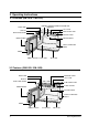
Operating Instructions 3-3 Control Panel (CM-1829 / CM-1429) 1 2 4 1 P 2 3 4 5 6 7 8 9 0 + 20sec 3 5 6 7 8 9 10 1. DISPLAY 2. PROGRAM PAD 3. PROGRAM LOCK PAD 4. NUMBER PADS(TIME, MEMORY PROGRAMMING) 5. POWER LEVEL SELECTOR PAD 6. DEFROST SELECTOR PAD 7. DOUBLE QUANTITY PAD 8. +20sec PAD (ONE TOUCH COOK PAD) 9. STOP/CANCEL PAD 10.
Operating Instructions 3-5 Operation Guide (CM-1819 / CM-1419) Cooking/Reheating 1. Make sure the oven is plugged into a properly earthed electrical outlet and ‘ON’ appears in the display window. 2. Open the door. The oven lamp will be turned on. 3. Put the food into a suitable container, place it in the center of the oven and then close the door securely. Result: The oven lamp will go off. 4. Select the desired power level by rotating the COOKING POWER CONTROL DIAL.
Operating Instructions 3-5 Operation Guide (CM-1819 / CM-1419 continued) To stop the cooking You can stop cooking at any time so that you can: • Check the food • Turn the food over or stir it • Leave it to stand * Temporarily ; Open the door or press button once. Result: Cooking stops. To resume cooking, close the door and press again. * Completely ; Press the button twice. Result: The cooking settings are cancelled.
Operating Instructions 3-5 Operation Guide (CM-1829 / CM-1429) Cooking/Reheating NOTE: When you first plug in the power cord, the oven beeps once and all the indicators show for 5 sec in the display window. NOTE: When heating cycle is completed and you open the door, the oven lamp automatically turns on and goes off 1 min later. NOTE: When you open the door whilst in a heating cycle, the oven stops operating and the oven lamp automatically turns on for 1 min and goes off 1 min later.
Operating Instructions 3-5 Operation Guide (CM-1829 / CM-1429 continued) Using the Defrost Feature NOTE: When the oven was operating for longer than 25 min under Defrosting cycle, you can NOT change the power level from Defrosting to Heating(Cooking/Reheating) mode. NOTE: The oven is designed not to work when power level is set to ‘0’ mode between the heating mode and the defrosting mode. * Use only containers that are microwave-safe. 1. Open the door. 2.
Operating Instructions 3-5 Operation Guide (CM-1829 / CM-1429 continued) Memory Pads Programming 1. Hold down PROGRAM LOCK pad and then press PROGRAM pad. Hold together for 2 sec. Be sure to press the pads firmly. Result: PROG indicator appears in the digital display. 2. Press appropriate NUMBER pad for the desired memory number. Result: Selected memory program code appears below the PROGRAM indicator. 3. Select power level by pressing the POWER LEVEL pad.
Operating Instructions 3-5 Operation Guide (CM-1829 / CM-1429 continued) How to Operate Memory Cooking After having finished memory programming, just press the NUMBER pad of the memory number you want to select. The oven will automatically start heating according to the pre-programmed cooking time and power level after a short delay (5 sec). 1. Make sure the oven is plugged into a properly earthed electrical outlet and ‘ON’ appears in the display window. 2. Open the door. The oven lamp will be turned on.
Operating Instructions 3-5 Operation Guide (CM-1829 / CM-1429 / CM-1819 / CM-1419) Power Levels and Time Variations The power level function enables you to adapt the amount of energy dissipated and thus the time required to cook or reheat your food, according to its type and quantity. You can choose between the power levels below. .....................................................................................................................................................
4. Disassembly and Reassembly 4-1 Replacement of Magnetron Remove the magnetron including the shield case, permanent magnet, choke coils and capacitors (all of which are contained in one assembly). Duct-MGT-L Nut-Flange 1. Remove the outer panel. NOTE: Before servicing, make sure to discharge electric charge remaining on the high voltage capacitors or wait for more than 5 min. 2. Remove the back cover. 3. Disconnect all lead wires from the magnetron. 4. Remove screws securing the duct-MGT and duct-fan. 5.
Disassembly and Reassembly 4-3 Replacement of Door Assembly 4-3-1 Removal of Door Assembly 4-3-2 Removal of Door Handle NOTE: Be sure to wear gloves when you disassemble or assemble the parts. 1. Remove hex bolts securing the upper hinge and lower hinge. Then remove the door assembly. 2. Insert the flat screwdriver or thin metal plate into the gap between the door E and door C to remove Door C from the door assembly. NOTE: Be careful when handling Door C as is fragile.
Disassembly and Reassembly 4-4 Replacement of Fuse and H.V.Fuse 1. Disconnect the oven from the power source. 2. Remove defective fuse from Noise filter. 3. When replacing the fuse, be sure to use an exact replacement part. If new fuse blows out again after replacement, check the primary interlock switch, door sensing switch and interlock monitor switch. 4.
Disassembly and Reassembly 4-6 Replacement of Control Box Ass’y and P.C.Board 6. Remove Control Box Ass’y. 7. To replace Digitron, remove 2 screws securing the PCB4. 8. To replace Start Button Circuitry, remove 3 screws securing the PCB3. (CM-1829/1429) 9. Unbend the metal tabs holding the Panel-Base to Control Box body. 4-6-1 Removal of Control Box Assembly 1. Be sure to discharge any static electric charge built up on your body and avoid touching the touch control circuitry. 2.
Disassembly and Reassembly 4-7 Replacement of Ventilation Motor 1. Remove the outer panel and back-cover. 2. Discharge the high voltage capacitor. 3. Remove all the lead wires from Magnetron and High Voltage Capacitor. 4. Remove 2 screws securing the duct fan. 5. Remove 2 screws securing the Supporter-FanMount. 6. Lift the Ventilation Motor Ass’y slightly upward and pull it out. 7. Remove lead wires and connectors. 8. Remove a screw securing the C-Film to the Supporter-Fan-Mount. 9.
Disassembly and Reassembly 4-10 Replacement of Air Filter 1. Pull out the spacer pins at both ends of the Air Filter. Then the locking clamps inside are released. 2. Lift the Air Filter off the post carefully. Note: Spacer pins are not detachable from the Air Filter. Plastic Spacer Pins 4-11 Replacement of High Voltage Capacitor NOTE: It is not necessary to remove Magnetron in order to remove HVC. 1. Remove the outer panel and back cover. 2. Discharge the high voltage capacitor. 3. Remove HVT wire and H.
5. Alignment and Adjustments PRECAUTION 1. High voltage is present at the high voltage terminals during any cook cycle. 2. It is neither necessary nor advisable to attempt measurement of the high voltage. 3. Before touching any oven components or wiring, always unplug the oven from its power source and discharge the high voltage capacitor. 5-1 High Voltage Transformer 1. Remove connectors from the transformer terminals and check continuity. 2.
Alignment and Adjustments 5-5 High Voltage Diode 1. Isolate the diode from the circuit by disconnecting its leads. 2. With the ohm-meter set at the highest resistance scale, measure across the diode terminals. Reverse the meter leads and read the resistance. A meter with 6V, 9V or higher voltage batteries should be used to check the front-to back resistance of the diode (otherwise an infinite resistance may be read in both directions).
Alignment and Adjustments 5-8 Output Power of Magnetron CAUTION MICROWAVE RADIATION PERSONNEL SHOULD NOT ALLOW EXPOSURE TO MICROWAVE RADIATION FROM MICROWAVE GENERATOR OR OTHER PARTS CONDUCTING MICROWAVE ENERGY. The output power of the magnetron can be measured by performing a water temperature rise test. Equipment needed : * Two 1-liter cylindrical borosilicate glass vessel (Outside diameter 190 mm) * One glass thermometer with mercury column NOTE: Check line voltage under load.
Alignment and Adjustments 5-10 Check for Microwave Leakage 5-10-1 Procedure for Measurement of Microwave Energy Leakage 1) Pour 275 ±15cc of 20°C±5°C ( 68°F±9°F ) water in a beaker which is graduated to 600cc, and place the beaker in the center of the oven. 2) Start to operate the oven and measure the leakage by using a microwave energy survey meter. 3) Set survey meter with dual ranges to 2,450MHz. 4) When measuring the leakage, always use the 2 inch spacer cone with the probe.
6. Troubleshooting PRECAUTION 1. CHECK GROUNDING BEFORE CHECKING FOR TROUBLE. 2. BE CAREFUL OF THE HIGH VOLTAGE CIRCUIT. 3. DISCHARGE THE HIGH VOLTAGE CAPACITOR. 4. WHEN CHECKING THE CONTINUITY OF THE SWITCHES OR TRANSFORMER, DISCONNECT LEAD WIRES FROM THESE PARTS AND THEN CHECK CONTINUITY WITHOUT THE POWER SOURCE ON. TO DO OTHERWISE MAY RESULT IN A FALSE READING OR DAMAGE TO YOUR METER. 5. DO NOT TOUCH ANY PART OF THE CIRCUIT OR THE CONTROL CIRCUIT BOARD, SINCE STATIC DISCHARGE MAY DAMAGE IT.
Troubleshooting 6-1 Electrical Malfunction(continued) SYMPTOM CAUSE CORRECTIONS Oven lamp goes off 1. Loose lead wire or open lamp filament 2. Misadjustment of latch switch 3. Defective latch switch Tighten lamp lead wire or replace with a new lamp Microwave output is low;. Oven takes longer time to cook food. (No heat while oven lamp and ventilation motor.) 1. Decrease in power source voltage. 2. Open or loose wiring of magnetron filament circuit. (Intermittent oscillation) 3. Aging of magnetron 4.
Troubleshooting 6-2 Error Codes & Corrections Code E1 Cause Corrections 1. Improper input power frequency 2. Defective Ass’y Main PCB Check if power frequency is 50Hz. E21 1. Thermistor sensor failure 2. Thermistor sensor open 3. Loose connector CN2 Check resistance of thermistor sensor and replace if defective. Check the circuitry around thermistor sensor. E22 1. Thermistor sensor failure Check resistance of Thermistor sensor and replace if defective. If Thermistor sensor is short, replace.
7.
Exploded Views and Parts List 7-2 Main Parts List No Parts No 1 2 3 4 5 6 7 7 8 8 9 10 11 12 13 14 15 16 17 18 18 18 18 19 19 20 21 22 23 24 25 26 27 28 29 30 31 32 33 34 35 36 37 38 39 40 40 40 40 41 41 41 41 DE70-30123A DE39-20075H DE71-60421A DE71-60422A DE03-30070A DE26-10150A 2501-001015 2501-001018 DE91-70061A DE91-70061C DE59-40001A DE26-20162A DE31-10180A DE61-30189A DE72-50088A DE72-50089A DE72-50090A DE61-50529A DE91-40105A DE91-10513A DE91-10515A DE91-10512A DE91-10514A DE39-40695A DE39-40113
Exploded Views and Parts List 7-2 Main Parts List (continued) No Parts No 42 43 44 45 46 47 48 49 50 51 52 53 54 DE63-90191E DE47-20197A DE92-10157A 3601-001034 2301-001204 3601-001126 DE93-90112A DE61-50541A DE71-60424A DE47-20017A DE32-10013A DE63-90191F DE39-40693A Parts Name CUSHION-GUIDE-E THERMOSTAT ASSY CAVITY FUSE-FERRULE C-FILM,PEF FUSE-FERRULE ASSY-B/RESISTOR BRACKET-EARTH COVER-CEILING THERMOSTAT SENSOR-THERMISTOR CUSHION-GUIDE-F WIRE HARNESS-A Description/Specification PUT-FOAM T10 W2 L450
Exploded Views and Parts List 7-3 Exploded View & Parts List - Door Parts 1 11 2 3 4 5 8 11 10 7 Ref. No. 1 2 3 4 5 6 7 8 9 10 11 Parts No.
Exploded Views and Parts List 7-4 Exploded View & Parts List - Control Parts (CM-1819/1419) 13 12 11 2 7 10 4 8 3 9 1 6 5 Ref. No 1 1 2 3 4 5 6 7 8 9 10 11 12 13 30 Parts No.
Exploded Views and Parts List 7-4 Exploded View & Parts List - Control Parts (CM-1829/1429) 9 1 10 2 11 8 5 4 1 7 3 6 Ref. No Parts No.
Exploded Views and Parts List 7-6 Parts List - Standard Parts Parts No.
P.C.B Circuit Diagrams and Parts List 8-2 P.C.
P.C.B Diagrams and Parts List 8-3 P.C.B Parts List (CM-1819/1419) Parts No.
P.C.B Diagrams and Parts List 8-3 P.C.B Parts List (CM-1819/1419 continued) Parts No. Parts Name Description / Specification Q'ty 2401-000180 2401-000466 2401-000598 2401-000914 2401-000941 2401-001268 2401-001362 2401-001412 2801-003214 3404-000282 3711-000203 3711-000940 3711-000999 DE13-20009A DE39-60001A C-AL C-AL C-AL C-AL C-AL C-AL C-AL C-AL CRYSTAL-UNIT SWITCH-TACT CONNECTOR-HEADER CONNECTOR-HEADER CONNECTOR-HEADER IC WIRE-SO COPPER 1000uF 20% 35V GP 16x25x7.
P.C.B Diagrams and Parts List 8-4 P.C.B Parts List (CM-1829/1429) Parts No. Parts Name Description / Specification Q'ty DE91-10513A 0604-000237 3002-000198 3501-001015 3501-001016 3708-000525 3711-000315 3711-000616 3711-001154 DE07-10088A DE13-20016A DE39-40113B DE39-40692A DE39-40694A DE61-90178A DE91-20593A 0401-001002 ASSY PCB-MAIN PHOTO-COUPLER BUZZER-PIEZO RELAY-POWER RELAY-MINIATURE CONNECTOR-FPC/FC/PIC CONNECTOR-HEADER CONNECTOR-HEADER CONNECTOR-HEADER V.F.
P.C.B Diagrams and Parts List 8-4 P.C.B Parts List (CM-1829/1429 continued) Parts No. 2401-000180 2401-000466 2401-000598 2401-000914 2401-000941 2401-001268 2401-001362 2401-001412 2801-003214 3404-000282 3711-000203 3711-000881 3711-000940 3711-000999 DE13-20009A DE39-60001A 38 Parts Name Description / Specification Q'ty C-AL C-AL C-AL C-AL C-AL C-AL C-AL C-AL CRYSTAL-UNIT SWITCH-TACT CONNECTOR-HEADER CONNECTOR-HEADER CONNECTOR-HEADER CONNECTOR-HEADER IC WIRE-SO COPPER 1000uF 20% 35V GP 16x25x7.
9.
Wiring Diagram & Operating Sequence 9-2 Description of Operating Sequence When the oven is set to power level of 100%, 70% or 50% When the oven is operating under the power level of 100%, 70% or 50%, the coil of power relay 1 and 2 are energized intermittently by ON and OFF cycle of 30 seconds in order to supply power source to the High Voltage Transformer and thus to oscillate the magnetron.
Wiring Diagram & Operating Sequence 9-2 Description of Operating Sequence (continued) Initial operating status of Power Relay when the START button is pressed. Relays are designed to work as shown in the figure below. When the oven is set to DEFROST power position, Inrush Relay1 and Power Relay1 are programmed to work with Inrush Relay2 and Power Relay2 not simultaneously but alternately.
Wiring Diagram & Operating Sequence 9-2 Description of Operating Sequence (continued) High Voltage Transformer input power sensing circuitry Refers to the circuitry that detects and check if the input power is correctly supplied to the primary terminal of High Voltage Transformer when the microwave oven is operating. If any abnormal condition(eg. Micro S/W, Relay open) is detected, the error code (E41, E42) shows on the display window.