MICROWAVE OVEN CM1019 / CM1029 SERVICE Manual CONTENTS MICROWAVE OVEN 1. Precaution 2. Specifications 3. Operating Instructions 4. Disassembly and Reassembly 5. Alignment and Adjustments 6. Troubleshooting P + 30sec 7. Exploded Views and Parts List 8. PCB Circuit Diagrams and Parts List 9.
1. Precaution Follow these special safety precautions. Although the microwave oven is completely safe during ordinary use, repair work can be extremely hazardous due to possible exposure to microwave radiation, as well as potentially lethal high voltages and currents. 1-1 Safety precautions ( ) 1. All repairs should be done in accordance with the procedures described in this manual. 2. Microwave emission check should be performed prior to servicing if the oven is operative. 3.
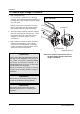
Precaution 1-2 Special High Voltage Precautions 1. High Voltage Warning Do not attempt to measureany of the high voltages--this includes the filament voltage of the magnetron. High voltage is present during any cook cycle. Before touching any components or wiring, always unplug the oven and discharge the high voltage capacitor (See Figure here) Discharge the 2 High Voltage Capacitors before servicing ! Screwdriver 2. The high-voltage capacitor remains charged about 30 seconds after disconnection.
2. Specifications 2-1 Table of Specifications (CM1019) ITEM MODEL CM1019 TIMER Max. 25 min POWER SOURCE 230V/50HZ, AC POWER CONSUMPTION MICROWAVE : 1,700W OUTPUT POWER 1,000W (IEC-705) OPERATING FREQUENCY 2,450MHz MAGNETRON OM75P(20)ESS COOLING METHOD FAN MOTOR OUTSIDE DIMENSIONS 464(W) x 368(H) x 557(D) NET WEIGHT 25 Kg SHIPPING WEIGHT 28 Kg 2-2 Table of Specifications (CM1029) ITEM MODEL CM1029 TIMER Max.
3.
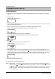
Operating Instructions 3-3 Control Panel (CM1029) 1 2 4 P + 30sec 3 5 6 7 8 9 10 1. DISPLAY 2. PROGRAM PAD 3. PROGRAM LOCK PAD 4. NUMBER PADS(TIME, MEMORY PROGRAMMING) 5. POWER LEVEL SELECTOR PAD 6. DEFROST SELECTOR PAD 7. DOUBLE QUANTITY PAD 8. +30sec PAD (ONE TOUCH COOK PAD) 9. STOP/CANCEL PAD 10.
Operating Instructions 3-5 Operation Guide (CM1019) Cooking/Reheating 1. Make sure the oven is plugged into a properly earthed electrical outlet and ÔONÕ appears in the display window. 2. Open the door. The oven lamp will be turned on. 3. Put the food into a suitable container, place it in the center of the oven and then close the door securely. Result: The oven lamp will go off. 4. Select the desired power level by rotating the COOKING POWER CONTROL DIAL.
Operating Instructions 3-5 Operation Guide (CM1019 continued) To stop the cooking You can stop cooking at any time so that you can: · Check the food · Turn the food over or stir it · Leave it to stand * Temporarily ; Open the door or press button once. Result: Cooking stops. To resume cooking, close the door and press again. * Completely ; Press the button twice. Result: The cooking settings are cancelled. If you want to cancel any cooking settings before starting cooking, simply press once.
Operating Instructions 3-5 Operation Guide (CM1029) Cooking/Reheating NOTE: When you first plug in the power cord, the oven beeps once and all the indicators show for 5 sec in the display window. NOTE: When heating cycle is completed and you open the door, the oven lamp automatically turns on and goes off 1 min later. NOTE: When you open the door whilst in a heating cycle, the oven stops operating and the oven lamp automatically turns on for 1 min and goes off 1 min later.
Operating Instructions 3-5 Operation Guide (CM1029 continued) Using the Defrost Feature NOTE: When the oven was operating for longer than 25 min under Defrosting cycle, you can NOT change the power level from Defrosting to Heating(Cooking/Reheating) mode. * Use only containers that are microwave-safe. 1. Open the door. 2. Place the frozen food in the centre of the plate tray. 3. Close the door. 4.
Operating Instructions 3-5 Operation Guide (CM1029 continued) Memory Pads Programming 1. Hold down PROGRAM LOCK pad and then press PROGRAM pad. Hold together for 2 sec. Be sure to press the pads firmly. Result: PROG indicator appears in the digital display. 2. Press appropriate NUMBER pad for the desired memory number. Result: Selected memory program code appears below the PROGRAM indicator. 3. Select power level by pressing the POWER LEVEL pad.
Operating Instructions 3-5 Operation Guide (CM1029 continued) How to Operate Memory Cooking After having finished memory programming, just press the NUMBER pad of the memory number you want to select. The oven will automatically start heating according to the pre-programmed cooking time and power level after a short delay (5 sec). 1. Make sure the oven is plugged into a properly earthed electrical outlet and ÔONÕ appears in the display window. 2. Open the door. The oven lamp will be turned on. 3.
Operating Instructions 3-5 Operation Guide (CM1019 / CM1029) Power Levels and Time Variations The power level function enables you to adapt the amount of energy dissipated and thus the time required to cook or reheat your food, according to its type and quantity. You can choose between the power levels below. ..................................................................................................................................................... Power Level Percentage CM1019/1029 ...............
4. Disassembly and Reassembly 4-1 Replacement of Magnetron Remove the magnetron including the shield case, permanent magnet, choke coils and capacitor (all of which are contained in one assembly). Duct-Fan Duct-MGT-L Nut-Flange 1. Remove the outer panel. NOTE: Before servicing, make sure to discharge electric charge remaining on the high voltage capacitors or wait for more than 5 min. 2. Remove the back cover. 3. Disconnect all lead wires from the magnetron. 4.
Disassembly and Reassembly 4-3 Replacement of Door Assembly 4-3-1 Removal of Door Assembly 4-3-2 Removal of Door Handle NOTE: Be sure to wear gloves when you disassemble or assemble the parts. 1. Remove hex bolts securing the upper hinge and lower hinge. Then remove the door assembly. 2. Insert the flat screwdriver or thin metal plate into the gap between the door E and door C to remove Door C from the door assembly. NOTE: Be careful when handling Door C as is fragile.
Disassembly and Reassembly 4-4 Replacement of Fuse and H.V.Fuse 1. Disconnect the oven from the power source. 2. Remove defective fuse from Noise filter. 3. When replacing the fuse, be sure to use an exact replacement part. If new fuse blows out again after replacement, check the primary interlock switch, door sensing switch and interlock monitor switch. 4.
Disassembly and Reassembly 4-6 Replacement of Control Box AssÕy and P.C.Board 6. Remove Control Box AssÕy. 7. To replace Digitron, remove 2 screws securing the PCB4. 8. To replace Start Button Circuitry, remove 3 screws securing the PCB3. (CM1029) 9. Unbend the metal tabs holding the Panel-Base to Control Box body. 4-6-1 Removal of Control Box Assembly 1. Be sure to discharge any static electric charge built up on your body and avoid touching the touch control circuitry. 2.
Disassembly and Reassembly 4-7 Replacement of Fan Motor 1. Remove the outer panel and back-cover. 2. Discharge the high voltage capacitor. 3. Remove all the lead wires from Magnetron and High Voltage Capacitor. 4. Remove 2 screws securing the duct fan. 5. Remove 2 screws securing the Supporter-FanMount. 6. Lift the Fan Motor AssÕy slightly left and pull it out. 7. Remove lead wires and connectors. 8. Turn the fan motor assÕy over so that the bracket side is up. 9. Remove 2 screws securing the Fan Motor.
Disassembly and Reassembly 4-10 Replacement of High Voltage Capacitor NOTE: It is not necessary to remove Magnetron in order to remove HVC. 1. Remove the outer panel and back cover. 2. Discharge the high voltage capacitor. 3. Remove HVT wire and H.V.Fuse. 4. Remove screws securing HVC bracket. H.V.
5. Alignment and Adjustments PRECAUTION 1. High voltage is present at the high voltage terminals during any cook cycle. 2. It is neither necessary nor advisable to attempt measurement of the high voltage. 3. Before touching any oven components or wiring, always unplug the oven from its power source and discharge the high voltage capacitor. 5-1 High Voltage Transformer 1. Remove connectors from the transformer terminals and check continuity. 2.
Alignment and Adjustments 5-5 High Voltage Diode 1. Isolate the diode from the circuit by disconnecting its leads. 2. With the ohm-meter set at the highest resistance scale, measure across the diode terminals. Reverse the meter leads and read the resistance. A meter with 6V, 9V or higher voltage batteries should be used to check the front-to back resistance of the diode (otherwise an infinite resistance may be read in both directions).
Alignment and Adjustments 5-8 Output Power of Magnetron CAUTION MICROWAVE RADIATION PERSONNEL SHOULD NOT ALLOW EXPOSURE TO MICROWAVE RADIATION FROM MICROWAVE GENERATOR OR OTHER PARTS CONDUCTING MICROWAVE ENERGY. The output power of the magnetron can be measured by performing a water temperature rise test. Equipment needed : * Two 1-liter cylindrical borosilicate glass vessel (Outside diameter 190 mm) * One glass thermometer with mercury column NOTE: Check line voltage under load.
Alignment and Adjustments 5-10 Check for Microwave Leakage 5-10-1 Procedure for Measurement of Microwave Energy Leakage 1) Pour 275 ±15cc of 20¡C±5¡C ( 68¡F±9¡F ) water in a beaker which is graduated to 600cc, and place the beaker in the center of the oven. 2) Start to operate the oven and measure the leakage by using a microwave energy survey meter. 3) Set survey meter with dual ranges to 2,450MHz. 4) When measuring the leakage, always use the 2 inch spacer cone with the probe.
6. Troubleshooting PRECAUTION 1. CHECK GROUNDING BEFORE CHECKING FOR TROUBLE. 2. BE CAREFUL OF THE HIGH VOLTAGE CIRCUIT. 3. DISCHARGE THE HIGH VOLTAGE CAPACITOR. 4. WHEN CHECKING THE CONTINUITY OF THE SWITCHES OR TRANSFORMER, DISCONNECT LEAD WIRES FROM THESE PARTS AND THEN CHECK CONTINUITY WITHOUT THE POWER SOURCE ON. TO DO OTHERWISE MAY RESULT IN A FALSE READING OR DAMAGE TO YOUR METER. 5. DO NOT TOUCH ANY PART OF THE CIRCUIT OR THE CONTROL CIRCUIT BOARD, SINCE STATIC DISCHARGE MAY DAMAGE IT.
Troubleshooting 6-1 Electrical Malfunction(continued) SYMPTOM CAUSE CORRECTIONS Oven lamp goes off 1. Loose lead wire or open lamp filament 2. Misadjustment of latch switch 3. Defective latch switch Tighten lamp lead wire or replace with a new lamp Microwave output is low;. Oven takes longer time to cook food. (No heat while oven lamp and ventilation motor.) 1. Decrease in power source voltage. 2. Open or loose wiring of magnetron filament circuit. (Intermittent oscillation) 3. Aging of magnetron 4.
Troubleshooting 6-2 Error Codes & Corrections Code E1 E5 (CM1029) Cause Corrections 1. Improper input power frequency 2. Defective AssÕy Main PCB Check if power frequency is 50Hz. Replace AssÕy Main PCB or MICOM. 1. Memory IC (EEPROM IC) failure 2. MICOM failure Check Memory IC (IC3) and replace if defective. Replace Assy Main PCB or MICOM.
7.
Exploded Views and Parts List 7-2 Main Parts List No. Parts No.
Exploded Views and Parts List 7-2 Main Parts List (continued) No.
Exploded Views and Parts List 7-3 Exploded View & Parts List - Door Parts 1 11 2 3 4 5 8 11 9 10 7 No. Parts No. 6 Parts Name Description/Specification Q'ty Remark 1 DE64-40298A DOOR-C PP CM1819 1 2 DE92-50132C ASSY DOOR-E CM1019 COATING BLK 1 3 DE64-90145A DECORATION-DOOR ABS CM1819 1 4 DE67-20174A SCREEN-DOOR(B) TEMP-GLASS T3.
Exploded Views and Parts List 7-4 Exploded View & Parts List - Control Parts (CM1019) 13 12 11 2 7 10 4 8 3 9 1 6 5 No. Parts No. Parts Name Description/Specification Q'ty Remarks 1 DE97-00052A ASSY PCB-MAIN CM1019 230V50Hz VFD 1 2 DE70-30126A PANEL-BASE RESIN-ABS ME CM1819 1 3 DE71-60427A COVER-PANEL STS430 T0.
Exploded Views and Parts List 7-4 Exploded View & Parts List - Control Parts (CM1029) 9 1 10 2 11 8 5 4 1 7 3 6 No. Parts No. Parts Name 1 DE97-00053A ASSY PCB-MAIN CM1029 230V50Hz VFD 1 2 DE70-30125A PANEL-BASE RESIN-ABS TC CM1829 1 3 DE34-10237B SWITCH-MEMBRANE PE-SHEET CM1029 230V0.5A 265X5 200GF 1 4 DE71-60426A COVER-PANEL STS430 T0.
Exploded Views and Parts List 7-6 Parts List - Standard Parts Parts No.
8. P.C.B Circuit Diagrams and Parts List 8-1 P.C.
P.C.B Circuit Diagrams and Parts List 8-2 P.C.
P.C.B Diagrams and Parts List 8-3 P.C.B Parts List (CM1019) Parts No. DE97-00052A Parts Name ASSY PCB-MAIN Description / Specification CM1019 230V50Hz VFD Q'ty Remarks 1 3002-000198 BUZZER-PIEZO 80dB 4KHz ST 1 BUZ1 3406-000175 SWITCH-ROTARY 28V 10mA DP36T 18.8mm 1 ECD2 3406-001032 SWITCH-ROTARY 28VDC 10mA DP6T 20mm 1 ECD1 3501-001015 RELAY-POWER 24V 21.8mA 16A 1FormA 20mS 10m 2 RY1,2 3501-001016 RELAY-MINIATURE 24V 12.
P.C.B Diagrams and Parts List 8-3 P.C.B Parts List (CM1019 continued) Parts No. 36 Parts Name Description / Specification Q'ty Remarks 2401-000180 C-AL 1000uF 20% 35V GP 16x25x7.5m 1 C01 2401-000466 C-AL 10uF 20% 35V GP TP 5x7 5 1 C05 2401-000598 C-AL 1uF 20% 50V GP TP 4x7 5 2 C08,C14 2401-000914 C-AL 22uF 20% 16V TP 5x11 5mm 1 C12 2401-002075 C-AL 22uF 20% 25V GP 5x11mm 5mm 1 C18 2401-001268 C-AL 4.
P.C.B Diagrams and Parts List 8-4 P.C.B Parts List (CM1029) Parts No. Parts Name Description / Specification Q'ty Remarks DE91-00053A ASSY PCB-MAIN CM1029 230V50Hz VFD 1 3002-000198 BUZZER-PIEZO 80dB 4KHz ST 1 BUZ1 3501-001015 RELAY-POWER 24V 21.8mA 16A 1FormA 20mS 10m 2 RY1,2 3501-001016 RELAY-MINIATURE 24V 12.5mA 5A 1FormA 8mS 4mS 3 RY3,4,6 3708-000525 CONNECTOR-FPC/FC/PIC 10P 2.54mm STRAIGHT SN 1 CN8 3711-000315 CONNECTOR-HEADER 1WALL 7P 1R 3.
P.C.B Diagrams and Parts List 8-4 P.C.B Parts List (CM1029 continued) Parts No. Parts Name Description / Specification Q'ty Remarks 2401-000180 C-AL 1000uF 20% 35V GP 16x25x7.5m 1 C01 2401-000466 C-AL 10uF 20% 35V GP TP 5x7 5 1 C05 2401-000598 C-AL 1uF 20% 50V GP TP 4x7 5 2 C08,14 2401-000914 C-AL 22uF 20% 16V TP 5x11 5mm 1 C12 2401-000941 C-AL 22uF 20% 25V GP 5x11mm 5mm 1 C18 2401-002075 C-AL 4.7uF 20% 50V GP 5x11mm 5mm 1 C13 2401-001363 C-AL 470uF 20% 16V GP 10x12.
9.
Wiring Diagram & Operating Sequence 9-2 Description of Operating Sequence When the oven is set to power level of 100%, 70% or 50% and Def. level 30% or 18% When the oven is operating under the power level of 100%, 70% or 50% and Def. level 30% or 18% the coil of power relay are energized intermittently by ON and OFF cycle of 30 seconds in order to supply power source to the High Voltage Transformer and thus to oscillate the magnetron.
Wiring Diagram & Operating Sequence 9-2 Description of Operating Sequence (continued) Initial operating status of Power Relay when the START button is pressed.