DIGITAL CAMCORDER SCD180 VP-D190MS/D190MSi SERVICE Manual For mechanical disassembly and adjustment, refer to the “Mechanical Manual” (CSM2000 AD68-30200A). DIGITAL CAMCORDER CONTENTS ✼ Service Tool 1. Precautions 2. Product Specifications and Comparison Chart 3. Disassembly and Reassembly 4. Alignment and Adjustment 5. Exploded View and Parts List 6. Electrical Parts List 7. PCB Diagrams © Samsung Electronics Co.,Ltd. Jun. 2002 Printed in Korea AD68-00564G 8. Wiring Diagram 9.
1. Precautions 1. Be sure that all of the built-in protective devices are replaced. Restore any missing protective shields. 2. When reinstalling the chassis and its assemblies, be sure to restore all protective devices, including : control knobs and compartment covers. 3. Make sure that there are no cabinet openings through which people--particularly children --might insert fingers and contact dangerous voltages.
Precautions 11. High voltage is maintained within specified limits by close-tolerance, safety-related components and adjustments. If the high voltage exceeds the specified limits, check each of the special components. 12. Design Alteration Warning : Never alter or add to the mechanical or electrical design of this unit. Example : Do not add auxiliary audio or video connectors. Such alterations might create a safety hazard. Also, any design changes or additions will void the manufacturer’s warranty. 13.
2. Product Specifications and Comparison Chart Operation Description System Video signal VP-D190MS/D190MSi: PAL, CCIR standards, SCD180: NTSC standards Video recording system 2 rotary heads, Helical scanning system Audio recording system Rotary heads, PCM system Usable cassette Digital video tape (6.35mm width): Mini DV cassette Tape speed SP: approx. 18.8mm/s Tape recording time SP: 60 minutes (when using DVM 60), LP: 90 minutes (when using DVM 60) FF/REW time Approx. 150 sec.
Products Specifications and Comparison Chart 2-2 Samsung Electronics
3. Disassembly and Reassembly 3-1. Cabinet and PCB 3-1-1 Ass’y Case Top Removal 1 Screw 2EA Removal 2 Bracket Accessory Shoe Removal 3 Screw 1EA Removal 4 Ass’y-Case Top Removal Fig.
Disassembly and Reassembly 3-1-2 Ass’y-Case Front Removal 2 Ass’y Case Front Removal 1 Screw 1EA Removal Fig.
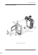
Disassembly and Reassembly 3-1-3 Ass’y Case Left Removal 6 Screw 1EA Removal 1 Screw 1EA Removal 3 Screw 1EA Removal 7 Ass’y-Case Left Removal 4 Screw 3EA Removal 5 Cover Connector Removal & 2 Screw 3EA LCD FPC Removal Removal Fig.
Disassembly and Reassembly 3-1-4 Ass’y LCD Removal 2 Ass’y-Cover LEFT Removal 1 Screw 2EA Removal 4 Ass’y LCD Removal 3 Screw 2EA Removal Fig.
Disassembly and Reassembly 3-1-5 Ass’y Right Removal 4 GYRO PCB Removal 3 Screw 1EA Removal Window-Remocon Removal 2 1 Screw 3EA Removal Fig.
Disassembly and Reassembly 3-1-6 Ass’y Right(2) Removal 1 Screw 1EA Removal 3 Screw 1EA Removal 2 Screw 2EA Removal A 4 Screw 2EA Removal B 6 Remove the Ass’y-Right in the direction of arrow A. 5 Screw 1EA Removal Fig.
Disassembly and Reassembly 3-1-7 Ass’y EVF Removal 2 Screw 2EA Removal 3 Ass’y-EVF Romoval 1 Screw 1EA Removal Fig.
Disassembly and Reassembly 3-1-8 Ass’y Main PCB Removal 2 Main PCB Removal 1 Screw 3EA Removal Fig.
4. Alignment and Adjustment 4-1. VCR Adjustment 4-1-1. VCR Adjustment Preparation 1. How to get into the VCR adjust mode. STEP 1 1. Connect the power source. 2. Set the mode switch of the video camera to "VCR" position. 3. Push the “TAPE EJECT” switch so that Door Housing is opened. STEP 2 1. Press and hold the "F.ADV" button on the remote control and "DISPLAY" button on the video camera at the same time for more than 5 seconds. 2.
Alignment and Adjustment Fig.1. RIGHT CASE Display Tape Eject Fig.2. REMOCON KEY STEP 3 . If you want to finish the adjustment mode, you have to do Power Reset. The Power Reset means that you pull out the power source and pull in it again.
Alignment and Adjustment 4-1-2. VCR Adjustment 1.
Alignment and Adjustment 4-2 Camera Adjustment Note: How to adjust the camera system. 1) EEPROM stores confirmed adjustment value of each adjustment step. 2) DSP (Digital Signal Process : ICP06-MAIN BOARD) digitalizes the camera signal. 3) When changing ICP08-MAIN BOARD of EEPROM, readjust main board. While changing LCD board- and EVF board- always readjust each part. Since EEPROM stores confirmed adjustment value of each adjustment step, readjusting must be performed in order to store the changed data.
Alignment and Adjustment 4. Functions of each button on the Remote Control Button START/STOP (Confirm) STOP (Data Down) PLAY (Data Up) FF (Mode Up) Description Stores changed value in the adjustment and auto adjustment mode. Changes data in the adjustment state. Changes mode. REW (Mode Down) In adjustment mode, the buttons of the remote control is as the followings. Note: In service adjustment mode, button names are different from those in customer function control mode. e.g.
Alignment and Adjustment model NTSC ADDR data PAL data d7 d6 d5 CONTENT d4 d3 d2 d1 d0 ODF 0CD 0CE 0CF 0D0 0D6 0DB 0DE FF FF FF FF FF FF FF FF FF FF FF FF FF FF FF FF CAMERA TABLE INITIAL( 'AA'+CONFIRM) AUTO HALL ADJUST AUTO IRIS ADJUST AUTO WB ADJUST (0D4:INDDOR, 0D5:OUTDOOR) AUTO LENS ADJUST(WARNING! DON'T USE WITHOUT AN INFINITE COLLIMATOR) ZOOM LEVER CENTER POSITION SETTING NO USED 3MM LENS AUTO ADJUST AT SERVICE FIELD(DISTANCE 3M+/-1Cm) 000 001 002 003 004 005 006 007 008 009 00A 00B 00C
Alignment and Adjustment model NTSC ADDR data 027 028 029 02A 02B 02C 02D 02E 02F 030 031 032 033 034 035 036 037 038 039 03A 03B 03C 03D 03E 03F 040 041 042 043 044 045 046 047 048 049 04A 04B 04C 04D 04E 04F 050 051 052 053 054 055 056 22 FF FF FF FF FF FF FF FF 45 38 78 20 78 80 90 30 CF 18 80 80 80 90 80 03 60 FF FF FF FF FF FF FF FF FF FF FF FF FF FF FF FF FF FF FF 02 FF FF PAL data 22 FF FF FF FF FF FF FF FF 4C 38 80 20 80 80 90 30 CF 18 80 80 80 90 80 03 60 FF FF FF FF FF FF FF FF FF FF FF FF FF F
Alignment and Adjustment model NTSC ADDR data 057 058 059 05A 05B 05C 05D 05E 05F 060 061 062 063 064 065 066 067 068 069 06A 06B 06C 06D 06E 06F 070 071 072 073 074 075 076 077 078 079 07A 07B 07C 07D 07E 07F 080 081 082 083 084 085 086 4-8 FF 01 10 30 2C 20 20 20 20 A5 30 52 5E 80 A0 81 C8 EC 21 84 84 10 01 10 10 09 20 0E 08 03 20 00 00 00 50 0A 08 00 00 05 00 16 24 00 06 04 02 60 PAL data FF 01 10 04 38 20 25 20 20 A1 2F 52 53 80 A0 81 C8 EE 21 84 84 20 01 12 10 10 20 0E 08 03 20 00 00 00 50 0A 08 00
Alignment and Adjustment model NTSC ADDR data 087 088 089 08A 08B 08C 08D 08E 08F 090 091 092 093 094 095 096 097 098 099 09A 09B 09C 09D 09E 09F 0A0 0A1 0A2 0A3 0A4 0A5 0A6 0A7 0A8 0A9 0AA 0AB 0AC 0AD 0AE 0AF 0B0 0B1 0B2 0B3 0B4 0B5 0B6 60 4E 48 00 02 01 00 02 02 15 2D 10 F0 F0 08 10 FF FF 28 04 0F F4 04 18 40 50 00 55 00 33 00 A0 00 40 89 60 4C 43 DD 07 0C 0C 10 15 00 58 20 75 PAL data 88 60 55 00 02 01 00 02 02 17 29 10 F0 F0 08 10 FF FF 28 04 0F F4 04 18 40 50 00 55 00 33 00 A0 00 40 89 60 4C 42 DD 0
Alignment and Adjustment model NTSC ADDR data 0B7 0B8 0B9 0BA 0BB 0BC 0BD 0BE 0BF 0C0 0C1 0C2 0C3 0C4 0C5 0C6 0C7 0C8 0C9 0CA 0CB 0CC 0CD 0CE 0CF 0D0 0D1 0D2 0D3 0D4 0D5 0D6 0D7 0D8 0D9 0DA 0DB 0DC 0DD 0DE 0DF 0E0 0E1 0E2 0E3 0E4 0E5 0E6 4-10 80 20 15 87 DC 00 5C 0B BA 81 07 89 C0 82 30 85 11 00 FF FF 1A 00 FF FF FF FF FF FF FF FF FF FF 00 FF FF FF FF FF FF FF FF 0A 40 00 58 E0 08 0A PAL data 80 20 19 87 DA 00 5B 0B A0 81 1A 89 C0 82 30 85 11 00 FB FF 19 00 FF FF FF FF FF FF FF FF FF FF 00 FF FF FF FF F
Alignment and Adjustment model NTSC ADDR data 0E7 0E8 0E9 0EA 0EB 0EC 0ED 0EE 0EF 0F0 0F1 0F2 0F3 0F4 0F5 0F6 0F7 0F8 0F9 0FA 0FB 0FC 0FD 0FE 0FF 100 101 102 103 104 105 106 107 108 109 10A 10B 10C 10D 10E 10F 110 111 112 113 114 115 116 0A 0F 06 F8 F0 0E 09 0C FF FF FF FF FF FF FF FF FF FF FF FF FF FF FF FF FF 00 00 9E 13 7A 33 A7 00 00 00 80 00 01 10 40 6E FF 04 00 00 01 30 00 PAL data 0A 0F 05 F3 E8 0E 09 0C FF FF FF FF FF FF FF FF FF FF FF FF FF FF FF FF FF 00 00 AD 04 0A 33 A6 00 00 00 80 00 00 10 3
Alignment and Adjustment model NTSC ADDR data 117 118 119 11A 11B 11C 11D 11E 11F 120 121 122 123 124 125 126 127 128 129 12A 12B 12C 12D 12E 12F 130 131 132 133 134 135 136 137 138 139 13A 13B 13C 13D 13E 13F 140 141 142 143 144 145 146 4-12 C0 01 B5 68 C0 C0 38 38 00 10 FB 1D 00 00 00 20 25 DC 01 7A 00 00 00 00 00 A8 0C CC 04 D8 78 E0 06 F8 7C 62 B1 59 8F 00 00 90 90 90 00 C0 52 35 PAL data C0 01 B5 68 00 C0 38 38 00 10 FD 1D 00 00 00 20 26 DD 02 92 00 00 00 00 00 A8 0C CC 04 D8 78 E0 06 F8 7C 62 B1 4
Alignment and Adjustment model NTSC ADDR data 147 148 149 14A 14B 14C 14D 14E 14F 150 151 152 153 154 155 156 157 158 159 15A 15B 15C 15D 15E 15F 160 161 162 163 164 165 166 167 168 169 16A 16B 16C 16D 16E 16F 170 171 172 173 174 175 176 00 00 00 00 00 00 00 00 00 A8 0C 50 0C B0 10 70 00 06 62 10 36 A5 2D 7F 00 06 46 66 0D FC 00 00 39 8A 24 59 D9 F2 72 B0 00 80 98 1B 22 4E 48 18 PAL data 00 00 00 00 00 00 00 00 00 A8 0C 50 0C A0 10 70 00 06 62 10 36 A5 2D 7F 00 06 46 66 0C FE 00 00 32 9D 24 59 D9 F2 72 B
Alignment and Adjustment model NTSC ADDR data 177 178 179 17A 17B 17C 17D 17E 17F 180 181 182 183 184 185 186 187 188 189 18A 18B 18C 18D 18E 18F 190 191 192 193 194 195 196 197 198 199 19A 19B 19C 19D 19E 19F 1A0 1A1 1A2 1A3 1A4 1A5 1A6 4-14 0D E8 10 04 00 07 EB E4 00 02 07 12 28 44 68 96 EA 02 07 12 28 44 68 96 EA 54 A8 26 5F 15 E4 0A 78 12 E7 1C 78 48 B0 23 5A 17 E7 08 76 FF 00 B0 PAL data 0A E8 10 04 00 07 EB E4 00 04 09 12 25 42 6A 96 EA 02 07 12 25 42 6A 96 EA 51 A6 2E 71 13 E0 0B 8E 13 E3 1C 8E 4
Alignment and Adjustment model NTSC ADDR data 1A7 1A8 1A9 1AA 1AB 1AC 1AD 1AE 1AF 1B0 1B1 1B2 1B3 1B4 1B5 1B6 1B7 1B8 1B9 1BA 1BB 1BC 1BD 1BE 1BF 1C0 1C1 1C2 1C3 1C4 1C5 1C6 1C7 1C8 1C9 1CA 1CB 1CC 1CD 1CE 1CF 1D0 1D1 1D2 1D3 1D4 1D5 1D6 40 B0 F0 04 00 00 00 00 00 01 F6 02 77 10 38 E0 1A 80 87 00 85 00 83 50 7C F9 38 38 04 B0 80 30 C0 9E 23 7A 00 5F 48 AA 00 90 12 90 0F BF 10 18 PAL data 40 B0 F0 04 00 00 00 00 00 01 F6 02 77 10 38 D0 1A 80 87 00 85 00 83 50 7C F9 38 38 04 B0 80 2A B8 AD 04 0A 00 5F 48 A
Alignment and Adjustment model NTSC ADDR data 1D7 1D8 1D9 1DA 1DB 1DC 1DD 1DE 1DF 1E0 1E1 1E2 1E3 1E4 1E5 1E6 1E7 1E8 1E9 1EA 1EB 1EC 1ED 1EE 1EF 1F0 1F1 1F2 1F3 1F4 1F5 1F6 1F7 1F8 1F9 1FA 1FB 1FC 1FD 1FE 1FF 4-16 10 00 00 38 09 05 1A 01 08 0C 04 59 00 60 00 00 00 00 00 00 00 00 00 00 00 A7 01 80 66 40 40 F8 F8 40 40 F8 F8 3B 56 24 19 PAL data 10 00 00 38 06 05 20 01 05 0C 04 41 00 60 00 00 00 00 00 00 00 00 00 00 00 A6 01 88 66 40 40 F8 F8 40 40 F8 F8 3B 56 24 19 d7 d6 d5 CONTENT d4 d3 d2 d1 d
Alignment and Adjustment 4-2-2 Camera Adjustment Note : "XX XX" indicate the previous preset value and adjusted value. Press the START/STOP (Confirm) button to store the adjusted value. CAMERA ADJ EPR:XX OCD EVR:XX (Stored value) (Adjusted value) 1. LENS ZOOM TRACK Caution : For whole zoom range, it shall be in focus. The location of a focus lens is moving depending on the location of zoom lens. During adjusting, micom measures the focus location from a near distance to a long.
Alignment and Adjustment 3. AUTO HALL 4. AUTO IRIS LEVEL 1) Camera mode & 3100˚ K gray scale chart 2) Connect a video output terminal to a TV. 3) Press the FF(Mode Up)/REW(Mode Down) button so that OSD shows "OCD XX XX". 4) Press the START/STOP (Confirm) button. 5) Then micom finds out max. Hall value with an iris opened and min. Hall value with an iris closed. Store max. and min. value of Hall in OAD and OAC respectively. 6) The OSD shows “OK” after finishing the adjustment.
Alignment and Adjustment 5. AUTO WHITE BALANCE (indoor) 1) Camera mode & 3100˚ K/5100˚ K gray scale chart 2) Connect a video output terminal to a vectorscope and a TV. 3) Press the FF(Mode Up)/REW(Mode Down) button so that OSD shows "OD4 XX XX". 4) Ensure that camera picks up image 40µs on 3100˚K gray scale chart precisely and the illumination is 1500-2000 Lux. 5) Press the START/STOP (Confirm) button to ensure that white spot on a vectorscope is moving in the middle of screen.
Alignment and Adjustment 8. R-Y NEGATIVE GAIN (indoor) 8-b. R-Y NEGATIVE GAIN (outdoor) 1) Camera mode & 3100˚ K color bar chart 2) Connect a video output terminal to a vectorscope and a TV. 3) Press the FF(Mode Up)/REW(Mode Down) button so that OSD shows "171 XX XX". 4) Ensure that camera picks up image on 3100˚ K color bar chart precisely and the illumination is 1500-2000 Lux. 5) Press the PLAY (Data Up)/STOP (Data Down) so that the cyan level is 60IRE.
Alignment and Adjustment 9. B-Y POSITIVE GAIN (indoor) 1) Camera mode & 3100˚ K color bar chart 2) Connect a video output terminal to a vectorscope and a TV. 3) Press the FF(Mode Up)/REW(Mode Down) button so that OSD shows "174XX XX". 4) Ensure that camera picks up image on 3100˚ K color bar chart precisely and the illumination is 1500-2000 Lux. 5) Press the PLAY (Data Up)/STOP (Data Down) so that the blue level is 40IRE. 6) Press the START/STOP (Confirm) button to store data.
Alignment and Adjustment 10-b. B-Y NEGATIVE GAIN (outdoor) 1) Camera mode & 5100˚ K color bar chart (3100°K color bar chart + C16 filter) 2) Connect a video output terminal to a vectorscope and a TV. 3) Press the FF(Mode Up)/REW(Mode Down) button so that OSD shows "O89 XX XX". 4) Ensure that camera picks up image on 5100˚ K color bar chart precisely and the illumination is 1500-2000 Lux. 5) Press the PLAY (Data Up)/STOP (Data Down) so that the yellow level is 48IRE.
Alignment and Adjustment 12. R-Y NEGATIVE HUE (indoor) 1) Camera mode & 3100˚ K color bar chart 2) Connect a video output terminal to a vectorscope and a TV. 3) Press the FF(Mode Up)/REW(Mode Down) button so that OSD shows "173 XX XX". 4) Ensure that camera picks up image on 3100˚ K color bar chart precisely and the illumination is 1500-2000 Lux. 5) Press the PLAY (Data Up)/STOP (Data Down) so that the cyan vector is 280˚ . 6) Press the START/STOP (Confirm) button to store data.
Alignment and Adjustment 13-b. B-Y POSITIVE HUE (outdoor) 1) Camera mode & 5100˚ K color bar chart (3100°K color bar chart + C16 filter) 2) Connect a video output terminal to a vectorscope and a TV. 3) Press the FF(Mode Up)/REW(Mode Down) button so that OSD shows "O71 XX XX". 4) Ensure that camera picks up image on 5100˚ K color bar chart precisely and the illumination is 1500-2000 Lux. 5) Press the PLAY (Data Up)/STOP (Data Down) so that the blue vector is 345˚ .
Alignment and Adjustment 4-3. LCD Adjustment Notes: For LCD adjustment, use the buttons on the video camera and the remote control. After each adjustment step is completed, OSD shows "OK". EEPROM(ICL202) stores confirmed adjustment value of each adjustment step. After finishing the adjustment, turn power off. 1. How to get into the LCD adjust mode. STEP 1 1. Connect the power source (battery/DC cable). 2. Set the "CAMERA/PLAYER" switch to "CAMERA" position. 3. Camera screen and OSD appears. 4.
Alignment and Adjustment 3. Adjust Mode NTSC PAL 00 55 55 01 55 (adjust) 55 (adjust) 02 80 (adjust) 80 (adjust) 03 83 (adjust) 83 (adjust) 04 80 (adjust) 80 (adjust) 05 89 89 06 89 89 07 FF FF 08 86 86 09 47 47 0A 55 55 0B 60 60 0C 80 80 0D 17 17 0F 17 17 10 FF FF 11 04 04 12 00 00 13 80 81 14 0C 0C 15 00 00 16 0A 0A 17 15 15 18 55 55 19 02 02 1A 02 02 4.
Alignment and Adjustment 3) Brightness a) Connect a probe to TP-G b) Check the wave form of Tp-G on screen of oscilloscope c) Move address to (01 USR BRT) USR BRT address number is 01 check and understand following figure. 4) Adjustment of TP-R a) Connect a probe (No. 1) to TP-G b) Connect a probe (No.
Alignment and Adjustment 5) Adjustment of TP-B How to adjust (TP-B) is on same process of TP-R Don’t forget! to you must compare TP-G with TPB too B 4-28 Samsung Electronics
Alignment and Adjustment 4-4. CVF Adjustment Notes : For CVF adjustment, use the buttons on the video camera and the remote control. After each adjustment step is completed, OSD shows "OK". EEPROM(ICV02) stores confirmed adjustment value of each adjustment step. After finishing the adjustment, turn power off. 1. How to get into the CVF adjust mode. STEP 1 1) Connect the power source (battery/DC cable). 2) Set the "CAMERA/VCR" switch to "CAMERA" position and LCD is close. 3) Camera screen and OSD appears.
Alignment and Adjustment 3. Adjust Mode NTSC PAL 00 55 55 01 55 (adjust) 55 (adjust) 02 90 (adjust) 90 (adjust) 03 90 (adjust) 90 (adjust) 04 80 (adjust) 80 (adjust) 05 89 89 06 89 89 07 FF FF 08 86 86 09 00 00 0A 80 80 0B 60 60 0C 80 80 0D 17 17 0F 19 (adjust) 19 (adjust) 10 00 00 11 04 04 12 00 00 13 00 01 14 0C 0C 15 06 06 16 0A 0A 17 15 15 18 FF FF 19 FF FF 1A FF FF 4. How to adjust LCD CONN.
Alignment and Adjustment 3) Brightness a) Connect a probe to TP-G b) Check the wave form of Tp-G on screen of oscilloscope c) Move address to (01 USR BRT) USR BRT address number is 01 check and understand following figure. R 5) Adjustment of TP-B How to adjust (TP-B) is on same process of TP-R Don’t forget! you must compare TP-G with TP-B too G 4) Adjustment of TP-R a) Connect a probe (No. 1) to TP-G b) Connect a probe (No.
Alignment and Adjustment (waveform of G and B) Adjust so that white level of G and B signal is same. (waveform of G and R) Adjust so that white level of G and R signal is same.
Alignment and Adjustment 4-5. EVF Adjustment 4-5-1. EVF adjustment Preparation STEP 1 STEP 2 1) Connect the power source (battery/DC cable). 2) Set the "POWER(CAMERA/PLAYER)" switch to "CAMERA" position. Press and hold the "EDIT(+)" button and "SELFTIMER" button on the video camera at the same time for more than 5 seconds. STEP 3 Press the “DISPLY” button to make color bar appear. LCD 01 MODE 1 EPR:XX EVR:XX Monitor screen Note : "XX" indicates variable values. 4-5-2.
Alignment and Adjustment 4-34 Samsung Electronics
5.
Exploded View and Parts List 5-1 Ass’y-Camera 5-2 Samsung Electronics
Exploded View and Parts List Loc.
Exploded View and Parts List 5-2 Ass’y EVF (SCD180) 5-4 Samsung Electronics
Exploded View and Parts List Loc. No New Part No Description and Specification Remark 150 155 157 159 161 165 166 167 169 170 171 172 174 175 176 177 908 ASSY-EVF;EVF(NTSC) COVER-LCD/LIGHT EVF;ABS 94-HB BLK HOLDER-LCD/LIGHT EVF;PC+G/F 20% BLK HOLDER-LENS EVF;ABS 94-HB BLACK KNOB-EVF;POM BLACK LENS-EVF UP G3;PMMA ASSY BL;EVF(0.24"") LCD-PANNEL;EVF(0.24"") BODY-LENS;PC BLACK BUTTON-LOCK;POM BLACK ASS'Y-EYE/CUP;ASSY BLACK HOUSING-EVF;PC BLACK SPRING-LOCK ;SWPB T0.
Exploded View and Parts List 5-3 Ass’y CVF (VP-D190MS/D190MSi) 5-6 Samsung Electronics
Exploded View and Parts List Loc. No New Part No Description and Specification Remark 151 154 156 158 160 162 163 164 169 170 171 172 174 175 176 178 198 199 908 ASSY-CVF CAP-LENS CVF;ABS 94-HB BLK COVER-LCD/LIGHT CVF;ABS 94-HB BLK HOLDER-LCD/LIGHT CVF;PC+G/F 20% BLK HOLDER-LENS CVF;ABS 94-HB BLACK KNOB-CVF;POM BLACK LENS-CVF UP G1;PMMA LENS-G2 CVF;PC BODY-LENS;PC BLACK BUTTON-LOCK;POM BLACK ASS'Y-EYE/CUP;ASSY BLACK HOUSING-EVF;PC BLACK SPRING-LOCK ;SWPB T0.
Exploded View and Parts List 5-4 Ass’y LCD 5-8 Samsung Electronics
Exploded View and Parts List List Loc. No New Part No Description and Specification 261 262 264 CASE-LCD BOTTOM INSULATION;BE-CU CASE-LCD TOP VP-D190MS CASE-LCD TOP VP-D190MSi CASE-LCD TOP SCD180 SHAFT-LCD;SUS303 KNOB-LCD;ABS 94HB BRKT-HOLDER;SUS304 1/2H T0.3 SPRING-LCD;SUS304-WPB T0.2 ASSY-BACK LIGHT;ASSY ASSY LCD BOARD;ASSY LCD DISPLAY;LCD SONY COVER-HINGE BOTTOM;ABS94HB L/GRAY (HF06601/G6238) COVER-HINGE TOP;Mg ASSY-LCD FPC; ASSY-HINGE; BADGE-SAMSUNG(26) SHEET-LCD;PET T0.
Exploded View and Parts List 5-5 Ass’y LEFT 5-10 Samsung Electronics
Exploded View and Parts List Loc. No New Part No Description and Specification 135 232 233 234 235 236 238 240 243 244 245 246 247 248 250 253 254 255 257 258 259 340 341 902 903 908 909 919 920 COVER-CONNECTOR; BRACKET-BATTERY EJECT;SUS T1.0 BUTTON-MENU;ABSB 94HB CASE-LEFT;Mg COVER-JACK DC;PE COVER-TERMINAL;PC V0+GLASS 15% HOLDER-TRIPOD;AL KNOB-BATTERY EJECT;AL SPRING-BATTERY EJECT;SWPB T0.2 INDICATOR-CHARGE;PMMA RED HOLDER-CHARGE;ABS 94HB BLK ASSY-DOOR JACK; ASSY-JACK BOARD; BRACKET-AV;SUS T1.
Exploded View and Parts List 5-6 Ass’y HOUSING (5) 5-12 Samsung Electronics
Exploded View and Parts List Loc. No New Part No 200 203 204 205 207 208 210 212 213 214 218 219 220 226 229 902 908 909 914 917 Description and Specification Remark AD97-05529A AD63-00354A AD97-03828A AD61-00809A AD64-00650A AD64-00651A AD64-00649A AD64-00652A AD61-00812A AD61-00795A AD97-04006A AD97-03830A AD63-00305A AD97-04027A AD63-00303A 6001-001526 ASSY-COVER HOUSING(MS) COVER-HOUSING;Mg ASSY-BELT GRIP;ASSY BRACKET-GRIP BACK;SUS304 1/2H T0.
Exploded View and Parts List 5-7 Ass’y RIGHT 5-14 Samsung Electronics
Exploded View and Parts List Loc. No New Part No 181 184 185 186 188 189 190 192 193 194 903 914 917 Description and Specification Remark AD97-03825A AD64-00641A AD61-00787A AD61-00818A 6044-000274 AD61-00807A AD97-04289A AD97-04357A AD61-00845A AD97-04003A 6001-001527 ASSY-LINK HOUSING;ASSY CASE-RIGHT;Mg BRACKET-GRIP FRONT;AL BRACKET-WASHER GRIP;SUS T0.3 RING-E;ID2.0,OD5,T0.4,PASS,STS304 SHAFT-GRIP;STS ASSY-SPEAKER;ASSY ASSY-CAP HOOD;BRACKET-LOCK HOLDER;SUS 1/2H T0.5 ASSY-ZOOM;SCREW-MACHINE;+CH(0.
Exploded View and Parts List 5-8 Mechanical Parts (1) (MAIN CHASSIS) 5-16 Samsung Electronics
Exploded View and Parts List Loc. No New Part No Description and Specification 302 303 304 305 402 403 M401 M402 M403 M404 M405 M406 M407 M408 M409 M410 M411 M412 M413 M414 M415 M416 SCREW-MACHINE;BH,+,M1.4,L2.5,BLK,SWRCH18 SCREW-MACHINE;TH,+,M1.4,L4.12,ZPC(YEL),S SCREW-MACHINE;BH,+,M1.4,L3.0,BLK(LOCK),S SCREW;-,BLK,L2.2,S45C-HC,BH,+,-,M1.4 WASHER-PLAIN;POLYSLIDE,-,ID0.8,D3.0,T0.2 WASHER-PLAIN;LUMINA,CUT,ID1.1,OD2.8,T0.
Exploded View and Parts List 5-9 Mechanical Parts (2) (SUB CHASSIS) 5-18 Samsung Electronics
Exploded View and Parts List Loc. No New Part No Description and Specification 301 401 402 S301 S302 S303 S304 S305 S306 S307 S308 S309 S310 S311 S312 S313 S314 S315 SCREW;BH,+,M1.4,D3.0 , WH WASHER-PLAIN;POLYSLIDER,-,ID0.8,D2.5,T0. WASHER-PLAIN;POLYSLIDE,-,ID0.8,D3.0,T0.2 SPRING-TENSION;DD-3,SUS304-WPB,•’0.12,-, SPRING-BRAKE S;DD-3,SUS304-WPB,•’0.18,-, SPRING-MAIN BRAKE T;DD-3,SWP-B,•’0.
Exploded View and Parts List 5-20 Samsung Electronics
6. Electrical Parts List Loc. NoPart No Desc & Spec ASSY-EIS BOARD Remark Loc.
Electrical Parts List Loc. No Part No Desc & Spec Remark Loc. NoPart No Desc & Spec Remark C109 2203-000438 C-CERAMIC,CHIP;1nF,10%,50V,X7R,TP,1005,- C316 2203-005061 C-CERAMIC,CHIP;100nF,+80-20%,16V,Y5V,TP, C110 2203-000812 C-CERAMIC,CHIP;0.
Electrical Parts List Loc. No Part No Desc & Spec Remark Loc. NoPart No Desc & Spec C512 2203-002717 C-CERAMIC,CHIP;10nF,+80-20%,50V,Y5V,TP,1 C901 2203-000234 C-CERAMIC,CHIP;0.
Electrical Parts List Loc. NoPart No Desc & Spec Remark Loc. NoPart No Desc & Spec Remark C956 2203-005923 C-CERAMIC,CHIP;1000NF,20%,6.3V,X5R,TP,16 CP05 C957 2203-005923 C-CERAMIC,CHIP;1000NF,20%,6.3V,X5R,TP,16 CP06 2203-005061 C-CERAMIC,CHIP;100nF,+80-20%,16V,Y5V,TP, 2203-005065 C-CERAMIC,CHIP;1000nF,+80-20%,10V,Y5V,TP C958 2203-005923 C-CERAMIC,CHIP;1000NF,20%,6.3V,X5R,TP,16 CP07 2203-005061 C-CERAMIC,CHIP;100nF,+80-20%,16V,Y5V,TP, C959 2203-005923 C-CERAMIC,CHIP;1000NF,20%,6.
Electrical Parts List Loc. No Part No Desc & Spec Remark Loc. NoPart No Desc & Spec CP52 2404-001020 C-TA,CHIP;10uF,20%,10V,GP,TP,3216,3.2 L102 2703-000396 INDUCTOR-SMD;10uH,10%,2.5x2x1.8mm CP53 2203-005061 C-CERAMIC,CHIP;100nF,+80-20%,16V,Y5V,TP, L103 2703-001883 INDUCTOR-SMD;22uH,10%,2.5x2x1.8mm CP54 2404-001247 C-TA,CHIP;22UF,20%,4V,WT,TP,2012 L201 2703-000396 INDUCTOR-SMD;10uH,10%,2.5x2x1.8mm CP55 2203-000330 C-CERAMIC,CHIP;0.
Electrical Parts List Loc. NoPart No Desc & Spec Remark Loc. NoPart No Desc & Spec Remark L931 2703-000408 INDUCTOR-SMD;3.3uH,20%,3.2x2.5x2.2mm Q917 0506-001066 TR-ARRAY;UMF5,NPN/PNP,2,150MW,SC-88,TP, L932 2703-001865 INDUCTOR-SMD;33UH,20%,6X6X2.8MM Q918 0506-001066 TR-ARRAY;UMF5,NPN/PNP,2,150MW,SC-88,TP, LP01 2703-001883 INDUCTOR-SMD;22uH,10%,2.5x2x1.8mm Q920 0504-000168 TR-DIGITAL;RN1104,NPN,100MW,47K/47K,SSM, LP02 2703-001883 INDUCTOR-SMD;22uH,10%,2.5x2x1.
Electrical Parts List Loc. NoPart No Desc & Spec Remark Loc. NoPart No Desc & Spec R255 2007-007589 R-CHIP;68Kohm,1%,1/16W,DA,TP,1005 R366 2007-000153 R-CHIP;22Kohm,5%,1/16W,DA,TP,1005 R256 2007-007589 R-CHIP;68Kohm,1%,1/16W,DA,TP,1005 R371 2007-007148 R-CHIP;3.
Electrical Parts List Loc. NoPart No Desc & Spec Remark Loc.
Electrical Parts List Loc. No Part No Desc & Spec Remark Loc. NoPart No Desc & Spec 2007-000140 R-CHIP;1Kohm,5%,1/16W,DA,TP,1005 R920 2007-000140 R-CHIP;1Kohm,5%,1/16W,DA,TP,1005 R657 2007-000162 R-CHIP;100Kohm,5%,1/16W,DA,TP,1005 R921 2007-007310 R-CHIP;8.2Kohm,1%,1/16W,DA,TP,1005 R701 2007-000140 R-CHIP;1Kohm,5%,1/16W,DA,TP,1005 R922 2007-000148 R-CHIP;10Kohm,5%,1/16W,DA,TP,1005 2007-007470 R-CHIP;7.
Electrical Parts List Loc. NoPart No Desc & Spec Remark Loc.
Electrical Parts List Loc. NoPart No Desc & Spec Remark Loc. NoPart No Desc & Spec C702 2203-000257 C-CERAMIC,CHIP;10nF,10%,50V,X7R,TP,1608 C767 2404-001246 C-TA,CHIP;10UF,20%,6.3V,WT,TP,2012 C703 2203-001140 C-CERAMIC,CHIP;68nF,10%,16V,X7R,TP,1608, C768 2203-000257 C-CERAMIC,CHIP;10nF,10%,50V,X7R,TP,1608 C704 2203-000604 C-CERAMIC,CHIP;22nF,10%,25V,X7R,TP,1608 C769 2203-000888 C-CERAMIC,CHIP;4.
Electrical Parts List Loc. NoPart No Desc & Spec Remark Loc. NoPart No Desc & Spec Remark R711 2007-000092 R-CHIP;15Kohm,5%,1/16W,DA,TP,1608 CC06 R712 2007-000134 R-CHIP;33Kohm,5%,1/16W,DA,TP,1608 CNC01 3708-000382 CONNECTOR-FPC/FFC/PIC;16P,0.5mm,ANGLE,SN 2404-000212 C-TA,CHIP;3.
Electrical Parts List Loc. NoPart No Desc & Spec Remark Loc. NoPart No Desc & Spec RV03 2007-000103 R-CHIP;120Kohm,5%,1/16W,DA,TP,1608 CM42 RV04 2007-000067 R-CHIP;15Kohm,1%,1/16W,DA,TP,1608 CM43 2203-005061 C-CERAMIC,CHIP;100nF,+80-20%,16V,Y5V,TP, RV05 2007-000772 R-CHIP;33Kohm,1%,1/16W,DA,TP,1608 CM50 2203-005061 C-CERAMIC,CHIP;100nF,+80-20%,16V,Y5V,TP, RV07 2007-000078 R-CHIP;1Kohm,5%,1/16W,DA,TP,1608 CM51 2404-001246 C-TA,CHIP;10UF,20%,6.
Electrical Parts List Loc. NoPart No Desc & Spec Remark Loc. NoPart No Desc & Spec Remark RM01 2007-000162 R-CHIP;100Kohm,5%,1/16W,DA,TP,1005 RM53 2007-000242 R-CHIP;1.
Electrical Parts List Loc. NoPart No Desc & Spec Remark Loc. NoPart No Desc & Spec CL129 2203-005887 C-CERAMIC,CHIP;680NF,+80-20%,10V,Y5V,TP, RL116 2007-000828 R-CHIP;39Kohm,1%,1/16W,DA,TP,1608 CL130 2203-005887 C-CERAMIC,CHIP;680NF,+80-20%,10V,Y5V,TP, RL117 2007-000090 R-CHIP;10KOHM,5%,1/16W,DA,TP,1608 CL131 2203-002793 C-CERAMIC,CHIP;1000nF,+80-20%,25V,Y5V,TP RL118 2007-000094 R-CHIP;22Kohm,5%,1/16W,DA,TP,1608 CL132 2203-001628 C-CERAMIC,CHIP;0.
Electrical Parts List Loc. No Part No Desc & Spec Remark Loc. NoPart No Desc & Spec Remark C51 2401-000037 C-AL;470uF,20%,16V,GP,TP,8x11.5,5 R16 2007-000768 R-CHIP;330OHM,5%,1/8W,DA,TP,3216 C55 2203-000239 C-CERAMIC,CHIP;0.
PCB Diagrams 7.
PCB Diagrams 7-1 Audio PCB (Component Side) 7-2 (Conductor Side) Samsung Electronics
PCB Diagrams 7-2 Main PCB (Component Side) Samsung Electronics (Conductor Side) 7-3
PCB Diagrams 7-3 EVF PCB (Component Side) 7-4 (Conductor Side) Samsung Electronics
PCB Diagrams 7-4 CVF PCB (Component Side) Samsung Electronics (Conductor Side) 7-5
PCB Diagrams 7-5 LCD PCB 7-6 Samsung Electronics
PCB Diagrams 7-6 CCD PCB (Component Side) Samsung Electronics (Conductor Side) 7-7
PCB Diagrams 7-7 EIS PCB (Component Side) 7-8 (Conductor Side) Samsung Electronics
PCB Diagrams 7-8 DSC PCB (Component Side) Samsung Electronics (Conductor Side) 7-9
PCB Diagrams 7-10 Samsung Electronics
8.
Wiring Diagram 8-2 Samsung Electronics
Schematic Diagrams 9.
Schematic Diagrams 9-1 System Control 9-2 Samsung Electronics
Schematic Diagrams 9-2 Servo Samsung Electronics 9-3
Schematic Diagrams 9-3 Timer 9-4 Samsung Electronics
Schematic Diagrams 9-4 Camera Samsung Electronics 9-5
Schematic Diagrams 9-5 DC/DC Converter 9-6 Samsung Electronics
Schematic Diagrams 9-6 Audio Samsung Electronics 9-7
Schematic Diagrams 9-7 Video 9-8 Samsung Electronics
Schematic Diagrams 9-8 DSC 1 Samsung Electronics 9-9
Schematic Diagrams 9-9 DSC 2 9-10 Samsung Electronics
Schematic Diagrams 9-10 Function Samsung Electronics 9-11
Schematic Diagrams 9-11 JACK BOARD 9-12 Samsung Electronics
Schematic Diagrams 9-12 TERMINAL SCHEMATIC Samsung Electronics 9-13
Schematic Diagrams 9-13 EVF 9-14 Samsung Electronics
Schematic Diagrams 9-14 LCD Samsung Electronics 9-15
Schematic Diagrams 9-15 CCD 9-16 Samsung Electronics
Schematic Diagrams 9-16 EIS Samsung Electronics 9-17
Schematic Diagrams 9-17 CVF 9-18 Samsung Electronics
표지 영문 2001.7.4 2:0 PM 페이지1 DIGITAL COMCORDER DECK CSM-2000 ◈ File with the SERVICE MANUAL. DIGITAL CAMCORDER DECK CONTENTS 1. Operation 2. Adjustment 3.
표지 영문 2001.7.4 2:0 PM 페이지2 ELECTRONICS Ⓒ Samsung Electronics Co., Ltd. APR.
1. 동작 영문 2001.7.4 2:3 PM 페이지1-1 1.
1. 동작 영문 2001.7.
1. 동작 영문 2001.7.4 2:3 PM 페이지1-3 1-2 Switch Modes Table 1-1 Switch Mode Code Modes signal 2+common Rotation Angle of Gear Mode Mechanical state EJECT 18kΩ -68.5°~ -46.6° Open housing UNLOAD 36 -4°~ 4° Standby Cassette down LD 1 54 51°~ 59° Idler Rotate and stop in loading mode LD 2 72 70°~ 140.8° Capstan Rotate in unload mode STOP 90 199.89°~ 207.85° stop PLAY 0 269.3°~ 288.5° In REC/PB/CUE/FF/PAUSE ※ Fig is based Eject Mode.
1. 동작 영문 2001.7.
1. 동작 영문 2001.7.4 2:3 PM 페이지1-5 Operation 1-3-2 Chassis Sub Mode Chassis Sub OFF Motor Loading ➊ rotates. ↓ Gear Wheel ➋ rotates. ↓ Gear Mode Switch ➌ rotates. ↓ Gear Cam Main ➍ rotates. ↓ Lever Cam ➍ rotates. ↓ Chassis Sub ➏ moves.
1. 동작 영문 2001.7.4 2:3 PM 페이지1-6 Operation 1-3-3 Brake S(SUB/MAIN) Mode Sub Brake Motor Loading ➊ rotates. ↓ Chassis Sub ➋ slides. ↓ Slide Main ➌ slides in direction of arrow. ↓ Brakes S ❹ released or operated to Reel Disk S ❺ by slide Main ❸.
1. 동작 영문 2001.7.4 2:3 PM 페이지1-7 Operation 1-3-4 Brake T Mode Motor Loading ➊ rotates. ↓ Chassis Sub ➋ slides. ↓ Slide Main ➌ slides in direction of arrow.
1. 동작 영문 2001.7.4 2:3 PM 페이지1-8 Operation 1-3-5 Arm Tension Mode Motor Loading ➊ rotates. ↓ Chassis Sub ➋ slides. ↓ Arm Tension ❻ slides in direction of arrow by Guide tension cam ❸ and cam curve A ❹ ↓ Brake tension ❼ released or operated connection with Arm Tension. ↓ After Loading finished, Arm Tension ❻ is controled by cam curve ❾ of Gear Mode Switch ❽.
1. 동작 영문 2001.7.4 2:3 PM 페이지1-9 Operation 1-3-6 Arm Pinch Mode Motor Loading ❶ rotates. ↓ Chassis Sub ❷ moves. ↓ Arm Pinch ❹ rotates cam curve A ❸ of Chassis Sub ❷. ↓ After Chassis Sub ❷ is finished loading, slider main ❺ slides in direction of arrow. ↓ Pinch Roller ❻ contacts shaft of Motor capstan ❼. ↓ Motor loading ❶ rotates in reverse. ↓ Slide main ❺ moves in reverse direction of arrow. ↓ Pinch Roller ❻ released from shaft of Motor Capstan ❼ by spring force of spring Lever pinch ❽.
1. 동작 영문 2001.7.4 2:3 PM 페이지1-10 Operation 1-3-7 Arm Review Mode Motor Loading ❶ rotates. ↓ Chassis Sub ❷ moves.
1. 동작 영문 2001.7.4 2:3 PM 페이지1-11 Operation 1-3-8 Pole Base S, T Mode Motor Loading ❶ rotates. ↓ Gear Wheel ❷ rotates. ↓ Gear Mode Switch ❸ rotates. ↓ Gear Cam Main ❹ rotates. ↓ Gear connector ❺ rotates. ↓ Arm Loading S and T are actuated by Gear Loading S ❻ and T ❼. ↓ Pole Base S ❽ and T ❾ slide along S and T rails. ↓ Pole Base S ❽ and T ❾ attach to V home of Base Drum .
1. 동작 영문 2001.7.4 2:3 PM 페이지1-12 Operation 1-3-9 Reel Driving Motor Capstan ❶ rotates. ↓ Gear Capstan ❷ rotates. ↓ Belt timming ❸ transmits rotation to Gear pully ❹. ↓ Gear Idler ❺ engages Reel Disk T ❻ or Reel Disk S ❻. ↓ Reel Disk T ❻ or Reel Disk S ❼ rotates.
1. 동작 영문 2001.7.4 2:3 PM 페이지1-13 1-4 Mode Transitions 1-4-1 Cassette in → Cassette down Cassette in By Catch ❶ of Housing release the Cassette-lid lock Housing down Chassis Sub’ s Cover stopper❷ opens cassette-lid By Key Release ❸ of Cover reel releases reel-lock of Cassette tape. Housing is locked by Lever lock ❹ and Chassis Sub’ s catch ❺ By Lever lock ❻ pushed Lever Eject ❼ and turns on S/W Cassette-in ❽.
1. 동작 영문 2001.7.4 2:4 PM 페이지1-14 Operation 1-4-2 Loading Cassette in Housing down. Motor Loading rotates. Gear Gear Gear Gear Gear ✽ This operation makes tape loading. Drum rotates. Worm Loading Motor Worm Loading Wheel Mode switch Cam Main rotate. Motor Capstan rotates. Gear Capstan, Belt Timing, Clutch and Gear ldler rotate in order. Chassis Sub moves in direction of arrow. Reel T rotates. Motor Capstan stops. Gear Connecter, Gear Loading S and T rotate.
1. 동작 영문 2001.7.
1. 동작 영문 2001.7.4 2:4 PM 페이지1-16 Operation 1-4-3 Stop → Play Push PLAY Key. Motor Loading rotates Forward. Drum rotates forward Gear Warm Motor, Gear Warm Loading Gear Wheel, Gear Mode switch Gear cam Main rotates Silder Main moves in direction of arrow. Brake S,T released from Reel S,T Arm Tension is moved in direction of arrow by Switch Mode’s Cam Curve causing tension to tape.
1. 동작 영문 2001.7.
1. 동작 영문 2001.7.4 2:4 PM 페이지1-18 Operation 1-4-4 Stop → FF Push FF Key. Motor Loading rotates foward. Drum rotates foward. Gear Worm Motor, Gear Worm Loading Gear Wheel, Gear Mode Switch Gear Cam Main rotates Slider Main moves in direction of arrow Brake S, T released from Reel S,T Arm Tension is moved in direction of arrow by Cam curve of Switch Mode causing tension to tape.
1. 동작 영문 2001.7.
1. 동작 영문 2001.7.4 2:4 PM 페이지1-20 Operation 1-4-5 Stop → REW Push REW Key. Motor Loading rotates forward. Drum rotates forward Gear Worm Motor Gear Worm Loading Gear Wheel,Gear Mode Switch Gear Cam Main rotate. Silder Main moves in direction of arrow. Arm Tension is moved in direction of arrow by switch cam of gear mode causing tension to tape Brake S released from Reel S, Pinch Roller moves in direction of arrow and attaches to Capstan Shaft, which puts the tape between roller and capstan shaft.
1. 동작 영문 2001.7.
1. 동작 영문 2001.7.4 2:4 PM 페이지1-22 Operation 1-4-6 Stop → REC Set Camera mode. Motor Loading rotates forward. Drum rotates forward. Gear Worm Motor, Gear Worm Loading Gear Wheel, Gear Mode switch, Gear Cam Main rotate. Silder Main moves in direction of arrow. Arm Tension is moved in direction arrow by Cam of Switch Mode. Pinch Roller moves in direction of arrow and attaches to Capstan Shaft Brake S, T released from Reel S, T Motor Capstan rotates in reverse. Motor Loading stops.
1. 동작 영문 2001.7.
1. 동작 영문 2001.7.4 2:4 PM 페이지1-24 Operation 1-4-7 Stop → Unload Push Eject key. Drum rotates forward. Motor Loading rotates in reverse. Gear Worm Motor, Gear Wheel Loading, Gear Wheel Worm, Gear Mode Switch, Gear Cam Main rotate. Motor Capstan rotates forward. Gear Connector, Gear Loading S,T rotates. Gear Capstan, Belt Timming, Gear Pully and Gear ldler rotate in order. Drum stops. Arm Loading S, T move in direction of arrow and Pole Base S, T silde.
1. 동작 영문 2001.7.
1. 동작 영문 2001.7.4 2:4 PM 페이지1-26 Operation 1-4-8 CUE Push FF Key. ✽ Act PLAY mode. Motor Capstan rotates approx. 10.5 times faster than PLAY mode. Gear Capstan, Belt Timming, Gear Pully, Gear Idler rotate in order. Reel S rotates approx. 10.5 times faster than PLAY mode. Reel T rotates approx. 10.5 times faster than PLAY mode. ✽ Tape fed by Motor Capstan is wound up to Reel T.
1. 동작 영문 2001.7.
1. 동작 영문 2001.7.4 2:4 PM 페이지1-28 Operation 1-4-9 REW Push REW Key. ✽ Act in PLAY mode. Motor Capstan Stops Motor Capstan rotates in reverse approx. 9.5 times faster than PLAY mode Gear Capstan, Belt timming,Gear pully and Gear Idler rotate in oncler Reel T rotates in reverse approx. 9.5 times faster than PLAY mode. Reel S rotates in reverse approx. 9.5 times faster tnan PLAY mode. ✽ Tape fed by Motor Capstan is wound up to Reel S.
1. 동작 영문 2001.7.
1. 동작 영문 2001.7.