SyncMaster UD46A, UD55A LCD Display User Manual The color and the appearance may differ depending on the product, and the specifications are subject to change without prior notice to improve the performance.
Safety Instructions Notational Note These safety instructions must be followed to ensure your safety and prevent property damage. Make sure to read the instructions carefully and use the product in the correct manner. Warning / Caution Failure to follow directions noted by this symbol could result in bodily harm or damage to the equipment.
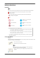
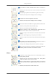
Safety Instructions Do not use a cleaning agent that contains alcohol or solvents, or that is surface active. Otherwise, the exterior may discolor or crack or the panel coating may come off. Do not spray water or cleaning agent directly onto the monitor. Otherwise, the liquid may sink into the monitor and cause a fire, electric shock, or failure. • Clean the exterior of the monitor using a soft cloth dampened with a small amount of water.
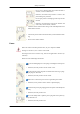
Safety Instructions Do not connect multiple appliances to the same power outlet. • Otherwise, this may cause fire due to overheating. Do not disconnect the power cord while using the product. • Otherwise, this may result in damage to the product due to electric shock. To disconnect the apparatus from the mains, the plug must be pulled out from the mains socket, therefore the mains plug shall be readily operable. • Otherwise, this may cause electric shock or fire.
Safety Instructions Do not install it in a badly ventilated location such as a bookcase or closet. • Otherwise, this may result in fire due to an increase in the internal temperature. When putting the product down, make sure to put it down softly. • Otherwise, this may result in damage to the screen display. Do not place the front of the product on the floor. • Otherwise, this may result in damage to the screen display. Ensure that an authorized installation company installs the wall mount.
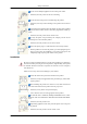
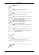
Safety Instructions Do not place this product in a location exposed to moisture, dust, smoke, water, or in a car. • Otherwise, this may result in electric shock or fire. When you drop the product or the case is broken, turn the power off and disconnect the power cord. Contact a Service Center. • Otherwise, this may result in electric shock or fire. During a lightning or thunderstorm, power off the product and remove the power cable. • Otherwise, this may result in electric shock or fire.
Safety Instructions Set a resolution and frequency appropriate to the product. • Otherwise, your eyesight may be damaged. When using headphones or earphones, do not turn the volume too high. • Having the sound too loud may damage your hearing. To avoid eyestrain, do not sit too close to the product. Take a rest for at least five (5) minutes after using the monitor for one (1) hour. This reduces eye fatigue.
Safety Instructions When replacing the battery, insert it with the right polarity (+, -). • Otherwise, the battery may become damaged or it may cause fire, personal injury or damage due to leakage of the internal liquid. Use only the specified standardized batteries, and do not use a new battery and a used battery at the same time. • Otherwise, the batteries may be damaged or cause fire, personal injury or damage due to a leakage of the internal liquid.
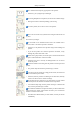
Safety Instructions Do not install the product in a location low enough for children to reach. • Otherwise, it may fall and result in personal injury. • Since the front part of the product is heavy, install the product on a level and stable surface. Do not put any heavy objects on the product. • This may result in personal injury and/or damage to the product. Precautions when handling the panel Do not stand the product as shown in the image. The panel is fragile and can get damaged.
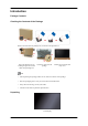
Introduction Package Contents Checking the Contents of the Package Remove the lock from the package box, as shown in the figure above. Lift up the package box by holding the grooves on both sides of the package box. Check the contents of the package. Remove the styrofoam and vinyl cover. Note • After unpacking the package, make sure to check the contents of the package. • Store the packaging box in case you need to move the Product later. • If any items are missing, contact your dealer.
Introduction Manuals Quick Setup Guide Warranty Card User Manual (Not available in some locations) Cables Power Cord D-Sub Cable Remote Control Batteries (AAA X 2) Holder Guide(4EA) (Not available in some locations) (For Video Wall) / Others Holder-Ring (4EA) / Screw (1EA) Screw (4EA) (For function knob) Screw (8EA) Sold separately Semi Stand KIT Wall Mount KIT TV Tuner Box (US Only)
Introduction Sold separately RGB to BNC Cable RGB to Component Cable Network Box HDMI to HDMI Cable Stereo Cable AV Cable DP Cable Bracket decoration (top, bottom, Left, Right) Screw (16EA) Note Accessories that can be purchased with the product vary by country. Your LCD Display Function knob The function knob has a remote-control sensor, a light sensor and function keys. If mounting the display onto a wall, you can move the function knob to the side of the display.
Introduction Automatically detects the intensity of ambient light around a selected display and adjusts the screen brightness. Note It work when you use the MDC program. Power indicator Shows PowerSaver mode by blinking green Note See PowerSaver described in the manual for further information regarding power saving functions. For energy conservation, turn your LCD Display OFF when it is not needed or when leaving it unattended for long periods.
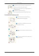
Introduction Attaching the knob to the side Attaching the function knob to the display • The function knob can be attached to any screw hole on the display. • Align the screw holes of the display and function knob. Next, fasten using the screw. Note Using a screw other than the one supplied can damage the display. Detaching the function knob Hold the area marked in the picture. Push the areas marked. Hold the areas marked, and lift the function knob.
Introduction IR OUT Receives a signal from the remote control and outputs the signal through Loopout when a removable sensor board is connected. CONTROL IN Connects to the function (Power/Source) control buttons and receives the light sensor signal and remote control's IR signal. DVI OUT (LOOPOUT) • Connect a monitor to another monitor through a DVI, DVI to HDMI cable. • Connect a DVI or DVI-HDMI cable to [DVI OUT (LOOPOUT)] on the product and [DVI IN] or [HDMI IN] on another monitor.
Introduction DVI IN (PC Video Connection Terminal) Connect the [DVI IN] port on the monitor to the DVI port on the PC using the DVI cable. RGB/DVI/DP/HDMI AUDIO IN (PC/DVI/ DP/HDMI Audio Connection Terminal (Input)) Connect the [RGB/DVI/DP/HDMI AUDIO IN] terminal of the monitor and the speaker output terminal of your computer's sound card using a stereo cable (sold separately). DP IN Receives a signal from the Display port.
Introduction Note • A normal external device (DVD player or camcorder, etc.) or a TV tuner box (US Only) can be connected to the [HDMI IN 1] terminal. • To use a TV tuner box (US Only), make sure to connect it to the [HDMI IN 1] terminal. HDMI IN 2 (MAGICINFO) • Connect the [HDMI IN 2 (MAGICINFO)] terminal at the back of your LCD Display to the HDMI terminal of your digital output device using a HDMI cable. • Up to HDMI 1.3 can be supported.
Introduction POWER ON/OFF Switches the LCD Display On/Off. POWER The power cord plugs into the LCD Display and the wall outlet. Kensington Lock slot An anti-theft lock allows you to use the product securely even in public places. The locking device shape and locking method depend on the manufacturer. Refer to the user guide provided with your anti-theft locking device for details. To lock the product, follow these steps: 1. Fix the cable of your anti-theft locking device to a heavy object such as a desk.
Introduction SOURCE OFF Number Buttons + VOL CONTENT (HOME) MagicInfo Lite TOOLS Up-Down Left-Right / Enter buttons RETURN The Color button / The PC/DVI/HDMI/DP selection button MagicInfo 3D ( )/ / / ( )/ D.MENU MUTE CH MENU BLANK INFO EXIT LOCK Power on the product. SOURCE OFF Number Buttons Select a connected source device. Power off the product. Enter the password in the OSD menu, or change the channel. Press to select additional channels(digital) being broadcasted by the same station.
Introduction Not available. CONTENT (HOME) Not available. MagicInfo Lite Quickly select frequently used functions. TOOLS - Enabled only when a TV tuner box(sold separately) is connected. Up-Down Left-Right / Enter buttons Up-Down Left-Right button : Move to the upper, lower, left or right menu, or adjust an option's setting. Enter button : Activates a highlighted menu item. Return to the previous menu.
Introduction Attaching the holders • Fix the holders into s on the back of the product using the screws. When displays are connected to form a video wall, the holders will make the gap between displays uniform on all four sides.
Introduction For a 3x3 video wall • To attach the decoration brackets to the sides of a video wall or Samsung UD installed, remove the stickers from the screw holes first. Note • Do not remove the stickers if you do not want to attach the decoration brackets. • To attach the decoration brackets to a 3x3 video wall, ensure you connect all the displays before attaching the brackets. User Installation Guide Note • Be sure to call an installation expert of Samsung Electronics to install the product.
Introduction • A Samsung Electronics service center can provide details. Tilt Angle and Rotation 1 2 1. The product can be tilted up to 15 degrees from a vertical wall. 2. To use the product in portrait mode, rotate it clockwise so that the LED indicator is at the bottom. Ventilation requirement 1. Vertical wall mount condition A : min.
Introduction 2. Embedded Mount guide A : min. 40 mm B : min. 70 mm C : min. 50 mm D : min. 50 mm E : Ambient temperature Measuring point < 35°C • When embedding the product in a wall, be sure there is some space behind the product for ventilation, as shown above, and maintain the ambient temperature at 35°C or lower. Note A Samsung Electronics service center can provide details.
Introduction Dimensions (unit:mm) UD55A
Introduction Notice • All drawings are not necessarily to scale. Some dimensions are subject to change without prior notice. • For securing the bracket on a wall, use only machine screws of 6 mm diameter and 8 to 12 mm length. Installing the Wall Mount Preparing before installing Wall-Mount To install a wall-mount from another manufacturer, use the Holder-Ring. Installing the Wall Mount Kit The wall mount kit (sold separately) allow you to mount the product on the wall.
Introduction Wall Mount Kit Specifications (VESA) Note Install your wall mount on a solid wall perpendicular to the floor. When attaching to other building materials, please contact your nearest dealer. If you install the product on a slanted wall, it may fall and result in severe personal injury. Note • Standard dimensions for wall mount kits are shown in the table below. • When purchasing our wall mount kit, a detailed installation manual and all parts necessary for assembly are provided.
Introduction pin TxD(No.2) RxD(No.3) GND(No.
Introduction Control codes • • • Get control Header command 0xAA command type DATA Length ID CheckSum 0 Set control Header command 0xAA command type ID DATA Length DATA 1 Value CheckSum commanding words No.
Introduction Header command ID 0xAA 0x11 Header command ID 0xAA DATA Length DATA 1 1 Power DATA Length DATA 1 1 1 0x11 CheckSum 12 If you want to control every mechanism connected with Serial Cable regardless of its ID, set ID part to "0xFE" and send commands. At the time, each product will follow commands but it will not respond with ACK. • Power Control • Function Personal Computer turns TV / Monitor power ON/OFF.
Introduction • Volume Control • Function Personal Computer changes volume of TV / Monitor. • • Get Volume Status Header command 0xAA 0x12 DATA Length ID CheckSum 0 Set Volume Header command ID 0xAA DATA Length DATA 1 Volume 0x12 CheckSum Volume : Volume value code to be set on TV / Monitor.
Introduction Input Source : Input Source code to be set on TV / Monitor. 0x14 PC 0x1E BNC 0x18 DVI 0x0C AV 0x04 S-Video 0x08 Component 0x20 MagicInfo 0x1F DVI_VIDEO 0x30 RF(TV) 0x40 DTV 0x21 HDMI1 0x22 HDMI1_PC 0x23 HDMI2 0x24 HDMI2_PC 0x25 DisplayPort Caution DVI_VIDEO, HDMI1_PC, HDMI2_PC → Get Only In the case of MagicInfo, only possible with models include MagicInfo In the case of TV, only possible with models include TV.
Introduction Caution Only works with models include TV. • • Get Screen Mode Status Header command 0xAA 0x18 DATA Length ID CheckSum 0 Set Picture Size Header command ID 0xAA DATA Length DATA 1 Screen Mode 0x18 CheckSum Screen Mode : Screen Mode code to be set on TV / Monitor.
Introduction • Ack Header command ID 0xAA 0xFF DATA Length Ack/Nak r-CMD Val1 3 ‘A’ 0x19 Screen Size Check Sum Screen Size : Screen Size of TV / Monitor. (Range : 0 ~ 255, Unit : Inch) • Nak Header command 0xAA 0xFF ID DATA Length Ack/Nak r-CMD Val1 3 ‘N’ 0x19 ERR Check Sum ERR : Error code that shows what occurred error is. • PIP ON / OFF Control • Function The PC turns the PIP function of a TV / Monitor ON / OFF. This does not operate in MagicInfo mode.
Introduction Header command 0xAA 0xFF ID DATA Length Ack/Nak r-CMD Val1 3 ‘N’ 0x3C ERR Check Sum ERR : Error code that shows what occurred error is. • Auto Adjustment Control (PC, BNC Only) • Function Personal Computer controls PC system screen automatically.
Introduction • • Get Video Wall Mode Header command 0xAA 0x5C DATA Length ID CheckSum 0 Set Video Wall Mode Header command 0xAA 0x5C ID DATA Length DATA 1 Video Wall Mode CheckSum Video Wall Mode : Video Wall Mode code to be set on TV / Monitor.
Introduction Header command ID 0xAA DATA Length DATA 1 Safety Lock 0x5D CheckSum Safety Lock : Lock code to be set on TV / Monitor. 1 : ON 0 : OFF • Ack Header command ID 0xAA 0xFF DATA Length Ack/Nak r-CMD Val1 3 ‘A’ 0x5D Safety Lock DATA Length Ack/Nak r-CMD Val1 3 ‘N’ 0x5D Safety Lock Check Sum Safety Lock : Same as above • Nak Header command ID 0xAA 0xFF ERR : Error code that shows what occurred error is.
Connections Connecting a Computer Note Do not connect the power cable before connecting all other cables. Ensure you connect a source device first before connecting the power cable. There are several ways to connect the computer to the monitor. Choose one from the following options. Using the D-sub (Analog) connector on the video card. • Connect the D-sub to the 15-pin, [RGB/COMPONENT IN] port on the back of your LCD Display and the 15 pin D-sub Port on the computer.
Connections • Connect the DVI Cable to the [DVI IN] port on the back of your LCD Display and the DVI port on the computer. Using the DP (Digital) connector on the video card. • Connect the [DP IN] port on the LCD Display to the DP port on the PC using the DP cable. Using the HDMI (Digital) connector on the video card. • Connect the [HDMI IN 1] port on the LCD Display to the HDMI port on the PC using the HDMI cable.
Connections Connecting to Other devices Note • Do not connect the power cable before connecting all other cables. Ensure you connect a source device first before connecting the power cable. • AV input devices such as DVD players, VCRs or camcorders as well as your computer can be connected to the LCD Display. For detailed information on connecting AV input devices, refer to the contents under Adjusting Your LCD Display.
Connections Connecting AV Devices 1. Connect an audio cable to [AV/COMPONENT AUDIO IN [R-AUDIO-L]] on the product and the audio port on an external device such as a VCR or DVD player. 2. Connect a video cable to [AV IN] on the product and the video output port on the external device. 3. Then, start the DVD, VCR or Camcorders with a DVD disc or tape inserted. 4. Press SOURCE on the product or remote control and select "AV". Connecting to a Camcorder 1. Locate the AV output jacks on the camcorder.
Connections 3. Press SOURCE on the product or remote control and select "AV". 4. Then, start the Camcorders with a tape inserted. Note The audio-video cables shown here are usually included with a Camcorder. (If not, check your local electronics store.) If your camcorder is stereo, you need to connect a set of two cables. Connecting Using a HDMI Cable 1. Connect an HDMI cable to [HDMI IN 2 (MAGICINFO)] or [HDMI IN 1] on the product and the HDMI output port on a digital device. 2.
Connections Connecting Using a DVI to HDMI Cable Connect a DVI-HDMI cable to [HDMI IN 2 (MAGICINFO)] or [HDMI IN 1] and the DVI output port on the digital device. Connect the red and white jacks of an RCA to stereo (for PC) cable to the same colored audio output terminals of the digital output device, and connect the opposite jack to the [RGB/DVI/DP/HDMI AUDIO IN] terminal of the LCD Display. 3.
Connections Note • Press SOURCE on the product or remote control and select "Component". • Then, start the DVD Player with a DVD disc inserted. • A RGB to component cable is optional. • For an explanation of Component video, consult your DVD manual. Connecting a DTV Set Top (Cable/Satellite) Box Connect a RGB to Component cable between the [RGB/COMPONENT IN] port on the LCD Display and the PR, Y, PB jacks on the Set Top Box.
Connections Connecting to an Audio System 1. Connect a set of Stereo Cable between the AUX L, R jacks on the AUDIO SYSTEM and [AUDIO OUT] on LCD Display. Connecting a Network Box (sold separately) Note • Network boxes are sold separately. • For more information on how to purchase and install a network box, contact Samsung Electronics. Connecting the Power Connect the [POWER] terminal of the product and the [POWER] terminal of the installed network box using a power extension cable.
Connections Connecting to MAGICINFO OUT Connect the MAGICINFO terminal on the network box to the HDMI IN2(MAGICINFO) terminal on the product using the MAGICINFO OUT-HDMI cable. Note A MAGICINFO OUT-HDMI cable is provided with the network box. Connecting a LAN Cable Connect the LAN cable between the [LAN] port on the network box and the [LAN] port on your PC.
Connections Connecting a USB devices You can connect USB devices such as a mouse or keyboard.
Using the Software Monitor Driver Note When prompted by the operating system for the monitor driver, insert the CD-ROM included with this monitor. Driver installation is slightly different from one operating system to another. Follow the directions appropriate for the operating system you have. Prepare a blank disk and download the driver program file at the Internet web site shown here. Internet web site : http://www.samsung.com/ Installing the Monitor Driver (Automatic) 1.
Using the Software Note This monitor driver is certified by Microsoft, and installing it will not damage your system. The certified driver will be posted on Samsung Monitor homepage. http://www.samsung.com/ Installing the Monitor Driver (Manual) Microsoft® Windows Vista™‚ Operating System 1. Insert your Manual CD into your CD-ROM drive. 2. Click 3. Click "Personalization" and then "Display Settings". 4. Click "Advanced Settings...". 5. Click "Properties" in the "Monitor" tab.
Using the Software Note This monitor driver is under certifying MS logo, and this installation will not damage your system. The certified driver will be posted on Samsung Monitor homepage. 6. Click "Update Driver..." in the "Driver" tab. 7. Check the "Browse my computer for driver software" checkbox and click "Let me pick from a list of device drivers on my computer". 8. Click "Have Disk...” and select the folder (for example, D:\Drive) where the driver setup file is located, and click "OK".
Using the Software 9. Select the model that matches your monitor from the list of monitor models on the screen, and click "Next". 10. Click "Close" → "Close" → "OK"→ "OK" on the following screens displayed in sequence.
Using the Software 1. Insert CD into the CD-ROM drive. 2. Click "Start" → "Control Panel", then click the "Appearance and Themes" icon. 3. Click "Display" icon and choose the "Settings" tab then click "Advanced...". 4. Click the "Properties" button on the "Monitor" tab and select "Driver" tab. 5. Click "Update Driver..." and select "Install from a list or..." then click "Next" button. 6. Select "Don't search, I will...", then click "Next" and then click "Have disk".
Using the Software 7. Click the "Browse" button then choose A:(D:\Driver) and choose your monitor model in the model list and click the "Next" button. 8. If you can see the following message window, then click the "Continue Anyway" button. Then click "OK" button. Note This monitor driver is certified by Microsoft, and this installation will not damage your system. The certified driver will be posted on Samsung Monitor homepage. http://www.samsung.com/ 9.
Using the Software 10. Monitor driver installation is completed. Microsoft® Windows® 2000 Operating System When you can see "Digital Signature Not Found" on your monitor, follow these steps. 1. Choose "OK" button on the "Insert disk" window. 2. Click the "Browse" button on the "File Needed" window. 3. Choose A:(D:\Driver), then click the "Open" button and then click "OK" button. How to install 1. Click "Start", "Setting", "Control Panel". 2. Double click the "Display" icon. 3.
Using the Software 4. Select the "Monitor" tab. 5. Click the "Change" button in the "Monitor Type" area. 6. Choose "Specify the location of the driver". 7. Choose "Display a list of all the driver in a specific location...", then click "Next" button. 8. Click the "Have Disk" button. 9. Specify A:\(D:\driver), then click "OK" button. 10. Select "Show all devices" and choose the monitor that corresponds to the one you connected to your computer and click "OK". 11.
Using the Software MDC Program Installation/Uninstallation Installation 1. Insert the installation CD into theCD-ROM drive. 2. Click the MDC Unified installation program. Note If a software installation window is not displayed on the main screen, install with the "MDC Unified"execution file in the MDC folder on the CD. 3. Click “Next” in the displayed Installation Wizard screen. 4. In the "License Agreement" window displayed, select "I accept the terms in the license agreement" and click "Next". 5.
What is MDC? Multiple display control "MDC" is an application that allows you to easily control multiple display devices simultaneously using a PC. Connecting to MDC Using MDC via RS-232C (serial data communications standards) An RS-232C serial cable must be connected to the serial ports on the PC and monitor.
Using MDC via Ethernet Enter the IP for the primary display device and connect the device to the PC. One display device can connect to another using an RS-232C serial cable.
Connection Management Connection management includes the Connection list and Connection list modification options. Connection list – Connection list shows the details of the connections such as connection setting (IP/ COM, Port No, MAC, and Connection Type), connection status, Set ID Range, and detected devices. Each connection can contain a maximum of 100 devices connected in serial daisy-chain fashion.
Auto Set ID Auto Set ID feature assigns a Set ID for all the LFDs connected in daisy-chain of a selected connection. There can be a maximum of 100 LFDs in a connection. The Set ID is assigned sequentially in the daisychain running from 1 to 99, and then finally to Set ID 0. Cloning Using the Cloning feature, you can copy the setting of one LFD and apply it to multiple selected LFDs. You can select specific tab categories or all tab categories for cloning, using the copy setting option window.
Command Retry This feature is used to specify the maximum number of times the MDC command will be retried in case of there being no reply or a corrupted reply from an LFD. The retry count value can be set using the MDC options window. The retry count value must be between 1-10. The default value is 1.
Getting Started with MDC 1 To start the program, click Start 2 Click Add to add a display device. z Programs Samsung MDC Unified. If the connection is established via RS232C, go to Serial and specify the COM Port.
z If the connection is established via Ethernet, enter the IP that was entered for the display device.
Main Screen Layout 1 6 5 4 2 3 1 Menu Bar Change the status of a display device or the properties of the program. 2 Device Category View a list of connected display devices or device groups. 3 Schedule Category View a list of schedules for display devices. 4 Set List Select the display device you want to adjust. 5 Modify the Set List Add, edit, regroup or delete sets. 6 Help Topics Display help topics for the program.
Menus You can power on or off a selected device or change the input source or volume of the device. Choose display devices from the list of sets, and select the Home tab. 1 Home Select an item and change the corresponding setting. Power z On: Power on a selected display. z Off: Power off a selected dis Input Input Source : Change the input source. z Input sources available can vary depending on the Display Device Models. The input source can be changed only for displays that are turned on.
This menu shows a list of display devices which have following errors - fan error, temperature error, brightness sensor error, or lamp error. Select a display device from the list. The Repair button will be enabled. Click the refresh button to refresh the error status of the display device. The recovered display device will disappear from the Fault Device List. Fault Device Alert Display device in which error is detected will be reported by email. Fill in all required fields.
Screen Adjustment The screen settings (contrast, brightness, etc.) can be adjusted. Choose display devices from the list of sets, and select the Picture tab. Custom Select an item and change the corresponding screen setting. z Color and Tint are not available if the input source is PC. z Red, Green, Blue and PC Screen Adjustment are not available if the input source is Video.
Options Dynamic Contrast Adjust the Dynamic Contrast for the selected display device. Gamma Control Change the gamma value for the selected display. Auto Motion Plus This option is used to view dynamic images. z Off: Disable the Auto Motion Plus function. z Clear: Set the level of Auto Motion Plus to clear. This mode is suitable to display vivid images. z Standard: Set the level of Auto Motion Plus to standard. z Smooth: Set the level of Auto Motion Plus to smooth.
Size Picture Size Adjust the screen size for the selected display device. The Detail item will be disabled if Picture Size is set to a mode that does not support detailed configuration. The -/+ buttons can be used to adjust Zoom. The screen can be relocated using the up/down/left/right buttons. Detail You can view details of the selected screen size. PC Screen Adjustment Frequency adjustment or fine-tuning is available by using the -/+ buttons in Coarse or Fine.
Sound Adjustment You can change the sound settings. Choose display devices from the list of sets, and select the Sound tab. The Bass or Treble item will be disabled if the item is not supported by the selected set. Bass Adjust the bass for the selected display. Treble Adjust the treble for the selected display. Balance (L/R) Adjust the volume of the left and right speakers of the selected display device. SRS TS XT Enable or disable the SRS TS XT effect for the selected display device.
System Setup Choose display devices from the list of sets, and select the System tab. Video Wall The Video Wall function can be used to display part of a whole picture or repeat the same picture on each of connected multiple display devices. Video Wall is enabled only when devices are in the group. Video Wall Enable or disable Video Wall. Format Select the format to display the split screen.
H Select the number of horizontal display devices. A maximum of 15 displays can be arranged in a row. A maximum of 6 can be assigned to V if 15 is assigned to H. V Select the number of vertical display devices. A maximum of 15 displays can be arranged in a row. A maximum of 6 can be assigned to V if 15 is assigned to H. Screen Position View the layout of displays (configured by the screen divider) or change the layout as required. Screen Position and Preview are enabled when Video Wall is set to on.
PIP Basic information required to adjust PIP will appear in the menu screen. z PIP will be disabled when Video Wall is ON. z Note that Picture Size is disabled when PIP is ON. PIP Size View the PIP Size of the current display. PIP Source Select a PIP input source. Sound Select Select and enable the sound from either the primary screen or secondary screen. Channel The channel can be changed if PIP Source is TV.
General User Auto Color Automatically adjust the screen colors. Available only in PC mode. Auto Power Set the product to automatically power on. Standby Control Set the standby mode to activate if an input source is not detected. Fan & Temperature Configure the settings required to detect the fan speed and internal temperature for the product's protection. Fan Control Select a method to configure the fan speed. Fan Speed Configure the fan speed.
Security Safety Lock Lock the on-screen menus. To unlock the menus, set Safety Lock to Off. Button Lock Lock the buttons on the display device. To unlock the buttons, set Button Lock to Off. OSD Display Source OSD Select whether to display a message when the Source is changed. Not Optimum Mode OSD Select whether to display a message when a non-compatible mode is selected. No Signal OSD Select whether to display a message when there is no input signal.
Time Clock Set Change the current time on the selected display device according to the time set on a PC. If the time is not set on the display device, null values will be displayed. Timer z On Time: Set the time to power on the selected display device. z Off Time: Set the time to power off the selected display device. z Volume: Specify the volume of the display device when it is powered on by On Time. z Source: Specify the input source of the display device when it is powered on by On Time.
Once EveryDay Mon~Fri Mon~Sat Sat~Sun Manual The checkboxes to select days of the week below Repeat are enabled only if Manual is selected. Holiday Management Holiday Management allows you to prevent devices that are set to be powered on by the Timer from turning on at a specified date. The Holiday Management function can be enabled or disabled in the Timer settings menu. z Add: You can specify holidays: Click the Add button in the Holiday Management window.
Screen Burn Protection Pixel Shift Move the screen slightly at specified time intervals to prevent screen burn-in. Screen Saver This function prevents screen burn-in when the screen of the selected display device is left idle for an extended period of time. z Interval: Set the interval to activate the Screen Saver. z Mode: The Time setting can vary for each Mode.
The Safety Screen function can be used to prevent screen burn-in when a stationary image displays on the screen of a display device for an extended period of time. Lamp Control Lamp Control is used to adjust the backlight to reduce power consumption. Automatically adjust the backlight of the selected display device at a specified time. If Manual Lamp Control is adjusted, Auto Lamp Control will automatically switch to Off. Manually adjust the backlight for the selected display.
2 Reset Reset Picture Reset the screen settings. Reset Sound Reset the sound settings. Reset System Reset the system settings. Reset All Reset the screen, sound and system settings at the same time. 3 Edit Column Select the items you want to display in the list of sets. 4 Information View the program information.
Other Functions Resizing a Window Place the mouse pointer on a corner of the program window. An arrow will appear. Move the arrow to customize the size of the program window.
Group Management Creating Groups Create groups and manage the list of sets on a group basis. Duplicate group names cannot be used. 1 Right-click and select Group>Edit in the display device list section on the left side of the program window. 2 In the Edit Group window displayed, click Add on the sub level or Add on the same level. z Add on the sub level: Create a sub-group under the selected group. z Add on the same level: Create a group on the same level as the selected group.
The Add on the same level button is enabled only if at least one group is created. 3 Enter the group name. Deleting Groups 1 2 3 Select a group name, and click Edit. In the Edit Group window displayed, click Delete. Click Yes. The group will be deleted. Renaming Groups 1 2 Select a group name, and click Edit. In the Edit Group window displayed, click Rename. Rename 3 If a cursor appears in the old group name, enter a new group name.
Schedule Management Creating Schedules Create and register a schedule on a group basis. 1 Click All Schedule List in the schedule section on the left side of the program window. The Add button will be enabled in the middle. 2 Click the Add button. The Add Schedule window will appear.
3 Click Add below the Device Group item, and select the group you want to add a schedule to. 4 Select Date&Time/Action and click OK. The schedule will be added and a list of schedules will appear in the set list window. z Device Group: Select a group. z Date&Time z Instant Execution: Run the schedule immediately. Timer Set the date, time and interval to run the schedule. Action: Select a function that will activate at the specified time and interval.
Troubleshooting Guide Issue The display you want to control does not appear on the system information chart. Solution 1. Check the connection of the RS232C cable (check that the cable is properly connected to appropriate serial port). 2. Check that another display with a duplicate ID is not connected. Connecting displays with a duplicate ID can cause the displays not to be shown due to data collision. 3. Check that the display ID is within the range of 0 and 99. (Change the ID using the Display menu.
How display properties are shown when multiple displays are used 1 2 3 When no display is selected: The default value is displayed. When one display is selected: Settings for the selected display are displayed. When two displays are selected (e.g. in sequence of ID 1 andID 3): The settings for ID 1 are displayed before the settings for ID 3. 4 When the All+Select checkbox is checked and all displays are selected: The default settings are displayed.
Adjusting the LCD Display Input Available Modes • PC / DVI / DisplayPort • AV • Component • HDMI • MagicInfo • TV Note • A TV tuner box (sold separately) must be connected to use the TV. (US Only) • MagicInfo can only be enabled when a network box is connected. Source List Use to select PC, HDMI or other external input sources connected to the LCD Display. Use to select the screen of your choice. 1. PC 2. DVI 3. AV 4. Component 5.
Adjusting the LCD Display However, the picture may display abnormally if the connected external input signal is different from the selected video signal. PIP Note The PIP function is not available when Video Wall is On. When external AV devices such as VCRs or DVDs are connected to the LCD Display , PIP allows you to watch video from those devices in a small window super-imposed on the PC Video signal. (Off/On) Note • PIP turns off when the LCD Display is switched to an external source.
Adjusting the LCD Display • HDMI : PC • Display Port : PC Size Changes the Size of the PIP window. Note Picture > Size will be changed to 16:9 when PIP is On. Position Changes the Position of the PIP window. Transparency Adjusts the Transparency of PIP windows.
Adjusting the LCD Display Edit Name Name the input device connected to the input jacks to make your input source selection easier. VCR / DVD / Cable STB / HD STB / Satellite STB / AV Receiver / DVD Receiver / Game / Camcorder / DVD Combo / DHR / PC / DVI PC / DVI Devices Note • The displayed devices differ depending on the external input mode. • When connecting a PC to the HDMI terminal, set Edit Name to PC. In other cases, set Edit Name to AV.
Adjusting the LCD Display Source AutoSwitch When the Source AutoSwitch is On, the display video source will automatically be searched for active video. The Primary Source selection will be activated, if the current video source is not recognized. Secondary source selection will become active, if no primary video source is available. If the primary or secondary source is not recognized, the display will search again, if no active video is found the display will show the no-input-signal message.
Adjusting the LCD Display Specify Primary Source for the automatic input source. Secondary Source Specify Secondary Source for the automatic input source. Picture [PC / DVI / DisplayPort / MagicInfo Mode] Available Modes • PC / DVI / DisplayPort • AV • Component • HDMI • MagicInfo • TV Note • A TV tuner box (sold separately) must be connected to use the TV. (US Only) • MagicInfo can only be enabled when a network box is connected.
Adjusting the LCD Display Recommended for displaying advertisements (e.g. videos or indoor or outdoor ads). 3. Custom Custom By using the on-screen menus, the contrast and brightness can be changed to your personal preference. Note • By adjusting the picture using the Custom function, MagicBright will change to Custom mode. • Not available when Dynamic Contrast is set to On. 1. Contrast Adjusts the Contrast. 2. Brightness Adjusts the Brightness. 3. Sharpness Adjusts the Sharpness. 4.
Adjusting the LCD Display Color Tone Note Not available when Dynamic Contrast is set to On. The color tones can be changed. 1. Off 2. Cool 3. Normal 4. Warm 5. Custom Note If you set the Color Tone to Cool, Normal, Warm, or Custom, the Color Temp. function is disabled. If you set the Color Tone to Off, the Color Control function is disabled Color Control Adjusts individual Red, Green, Blue color balance. Note Not available when Dynamic Contrast is set to On. 1. Red 2. Green 3.
Adjusting the LCD Display Note • Not available when Dynamic Contrast is set to On. • This function is only enabled if the Color Tone is set to Off. Image Lock Image Lock is used to fine-tune and get the best image by removing noise that creates unstable images with jitters and shakiness. If satisfactory results are not obtained using the Fine adjustment, use the Coarse adjustment and then use Fine again. Note Available in PC mode only. Coarse Removes noise such as vertical stripes.
Adjusting the LCD Display Note • Not available when Dynamic Contrast is set to On. • Available in PC mode only. Signal Balance Selects either On or Off with the signal balance. Signal Control Note Available when Signal Balance is set to On. 1. R-Gain 2. G-Gain 3. B-Gain 4. R-Offset 5. G-Offset 6.
Adjusting the LCD Display Size The Size can be switched. 1. 16:9 2. 4:3 HDMI Black Level When a DVD or set-top box is connected to your product via HDMI or DVI port, it may cause a degradation in the screen quality, such as an increase in the black level, a low contrast, or discoloration, etc., depending on the external device connected. In this case, adjust the screen quality of your product by configuring the HDMI Black Level. 1. Normal 2.
Adjusting the LCD Display Adjusts the Brightness of the PIP window on the screen. 3. Sharpness Adjusts the Sharpness of the PIP window on the screen. 4. Color Adjusts the Color of the PIP window on the screen. Note PIP input only operates in DVI, AV, HDMI, or Component mode. 5. Tint Adds a natural tone to the PIP window. Note PIP input only operates in DVI, AV, HDMI, or Component mode.
Adjusting the LCD Display Uniformity Enhancer Make the screen brightness even throughout the whole screen. 1. Off 2. On Picture Reset Reset the screen settings. Picture [ AV / HDMI / Component / TV Mode] Available Modes • PC / DVI / DisplayPort • AV • Component • HDMI • MagicInfo • TV Note Mode • A TV tuner box (sold separately) must be connected to use the TV. (US Only) • MagicInfo can only be enabled when a network box is connected.
Adjusting the LCD Display The LCD Display has four automatic picture settings ("Dynamic", "Standard", "Movie" and "Custom") that are preset at the factory. Dynamic, Standard, Movie, or Custom can be activated. Note Not available when Dynamic Contrast is set to On. 1. Dynamic 2. Standard 3. Movie 4. Custom Custom By using the on-screen menus, the contrast and brightness can be changed to your personal preference. Note Not available when Dynamic Contrast is set to On. Contrast Adjusts the Contrast.
Adjusting the LCD Display Color Tone The color tones can be changed. The individual Color components are also user adjustable. Note Not available when Dynamic Contrast is set to On. 1. Off 2. Cool2 3. Cool1 4. Normal 5. Warm1 6. Warm2 Note If you set the Color Tone to Cool2, Cool1, Normal, Warm1, or Warm2, the Color Temp. function is disabled. Color Temp. Color temp. is a measure of the 'warmth' of the image colors.
Adjusting the LCD Display Video mode (HDMI [Video Timing], AV or Component): 16:9 - Zoom1 - Zoom2 - 4:3 - Screen Fit - Custom 1. 16:9 - Sets the picture to 16:9 wide mode. 2. Zoom 1 - Magnifies the size of the picture on the screen. 3. Zoom 2 - Magnifies the size of the picture more than Zoom 1. 4. 4:3 - Sets the picture to 4:3 normal mode. 5. Screen Fit - Displays the input scenes as they are without any cutoff when HDMI 720p, 1080i, 1080p signals are input. 6.
Adjusting the LCD Display etc., depending on the external device connected. In this case, adjust the screen quality of your product by configuring the HDMI Black Level. 1. Normal 2. Low Note For Timing which can be used for both the PC and the DTV in HDMI and DTV mode, HDMI Black Level will be activated. Film Mode Film Mode calibrates unnatural pictures that may occur in a movie (which is in 24 frames). Moving subtitles may appear corrupted when this mode is enabled.
Adjusting the LCD Display Adjusts the Sharpness of the PIP window on the screen. Dynamic Contrast Dynamic Contrast automatically detects the distribution of the visual signal and adjusts to create an optimum contrast. 1. Off 2. On Note Disabled when PIP is set to On. Lamp Control Adjusts the inverter lamp in order to reduce energy consumption. Note Not available when Dynamic Contrast is set to On. Uniformity Enhancer Make the screen brightness even throughout the whole screen. 1. Off 2.
Adjusting the LCD Display Sound Available Modes • PC / DVI / DisplayPort • AV • Component • HDMI • MagicInfo • TV Note • A TV tuner box (sold separately) must be connected to use the TV. (US Only) • MagicInfo can only be enabled when a network box is connected. Mode The LCD Display has a built-in high fidelity stereo amplifier. 1. Standard Selects Standard for the standard factory settings. 2. Music Selects Music when watching music videos or concerts. 3.
Adjusting the LCD Display Note • You can hear the sound even when sound value is set to 0. • If you adjust sound using Custom function, Mode will turn to Custom mode. Bass Emphasizes low frequency audio. Treble Emphasizes high frequency audio. Balance Allows you to Adjusts the sound balance between the left and right speakers. Auto Volume Reduces the difference in volume control between broadcasters. 1. Off 2.
Adjusting the LCD Display 1. Off 2. On Sound Select Enable the sound of either the primary or secondary display in PIP mode. Note Available when PIP is set to On. 1. Main 2. Sub Sound Reset Reset the sound settings. Setup Available Modes • PC / DVI / DisplayPort • AV • Component • HDMI • MagicInfo • TV Note • A TV tuner box (sold separately) must be connected to use the TV. (US Only) • MagicInfo can only be enabled when a network box is connected.
Adjusting the LCD Display Language You can choose one of 14 languages. Note The language chosen affects only the language of the OSD. It has no effect on any software running on the computer. Time Clock Set, Sleep Timer, Timer1 / Timer2 / Timer3, and Holiday Management can be set. Clock Set Current Time Setting. Sleep Timer Turns the LCD Display off automatically at certain times. 1. Off 2. 30 3. 60 4.
Adjusting the LCD Display 5. 120 6. 150 7. 180 Timer1 / Timer2 / Timer3 You can set the LCD display to automatically turn on or off at a specified time. Note • Holiday : Select Apply to disable the timer on holidays and Don't Apply to enable the timer on holidays. • Only enabled when the clock is set using the Clock Set menu. • The Manual option allows you to select a day of the week. • Source : Selects the external input source that will be displayed when the selected monitor is turned on.
Adjusting the LCD Display • Delete Selected You can delete selected holidays. Note • • Only enabled when registered holidays are selected. • More than one holiday can be selected and deleted. Delete All You can delete all the registered holidays. Menu Transparency Change the transparency of the background of the OSD. 1. High 2. Medium 3. Low 4.
Adjusting the LCD Display Safety Lock Change PIN The password can be changed. The preset password for the LCD Display is "0000". Note If you forgot your password, press the remote buttons INFO →EXIT →MUTE to reset the password to "0000." Lock This is the function that locks the OSD in order to keep the current settings or to prevent others from adjusting the settings. Note Selecting Lock On will enable Lock Off. To disable the Lock function, enter the password for Lock Off.
Adjusting the LCD Display Video Wall A Video Wall is a set of video screens connected together, so that each screen shows a part of the whole picture or where the same picture is repeated on each screen. When the Video Wall is on, you can adjust the Video Wall screen setting. Note • When a Horizontal or Vertical split is over four, use a resolution of XGA (1024 x 768) or greater to prevent any picture degradation. • Size will be disabled when Video Wall is running. • Disabled when PIP is set to On.
Adjusting the LCD Display Horizontal Sets how many parts the screen should be divided horizontally. Fifteen adjustment levels: 1~15. Note If Vertical is set to 15, the maximum value for Horizontal is 6. Vertical Sets how many parts the screen should be divided vertically. Fifteen adjustment levels: 1~15. Note If Horizontal is set to 15, the maximum value for Vertical is 6. Screen Position The screen can be divided into several images.
Adjusting the LCD Display Note When more than four displays are connected, we recommend a resolution of XGA (1024*768) or greater to prevent any picture degradation. Safety Screen The Safety Screen function is used to prevent afterimages that may appear when a still picture is displayed on the screen over a long time. Note This function is not available when the power is turned off.
Adjusting the LCD Display Sets how many pixels the screen moves vertically. Five adjustment levels: 0, 1, 2, 3, and 4. Time Set the time interval for performing the horizontal or vertical movement, respectively. Timer Timer You can set the timer for Screen Burn Protection. If you start the operation to erase any residual image, the operation will be performed for the set period of time and then automatically finish. • Off • On Mode You can change the Safety Screen Type.
Adjusting the LCD Display Period Use this function to set the execution period for each mode set in the timer. Time Within the set period of time specify a time for execution. • Mode - Bar, Eraser, Pixel : 10~50 sec Bar This function prevents after-images on the screen by moving long black and white vertical lines. Eraser This function prevents after-images on the screen by moving a rectangular pattern.
Adjusting the LCD Display Pixel This function prevents after-images by moving many pixels on the screen. Side Gray Select the brightness of the grey for the screen background.
Adjusting the LCD Display 5. 1366 X 768 Note Selecting the menu is only allowed when the graphics resolution is set to 1024 x 768 @ 60Hz, 1280 x 768 @ 60Hz, 1360 x 768 @ 60Hz or 1366 x 768 @ 60Hz. Power On Adjustment Adjusts the Power On time for the screen. Caution: Set the Power On time to be longer to avoid overvoltage. OSD Rotation OSD Rotate 1. Landscape 2. Portrait Advanced Settings Configures the settings more elaborately.
Adjusting the LCD Display Fan Control (UD46A model Only) Selects auto or manual for the fan speed settings. • Auto • Manual Fan Speed Setting(UD46A model Only) Sets the fan speed within a range of 0 and 100. Note Enabled when Fan Control is set to Manual. Temperature Control Detects the product's internal temperature and specifies the desired temperature. The product is set to 77°C by default.
Adjusting the LCD Display Current Temperature Shows the current temperature of the product. Auto Power Enables or disables Auto Power for the product. • Off • On Note When Auto Power is On, the product will power on automatically as soon as it is connected to power. Button Lock Locks or unlocks the monitor control buttons on the product.
Adjusting the LCD Display User Auto Color 1. Auto Color Automatically adjusts the colors. 2. Reset Resets the color settings. Note Enabled only in PC mode. Standby Control Sets the standby mode, which will be activated when no input signal is detected. • Off A message will read if no input signal is detected. • On Power-saving mode will be activated if no input signal is detected.
Adjusting the LCD Display Lamp Schedule Adjusts the luminance to a user-specified value at a specified time. OSD Display Displays or hides a menu item on the screen.
Adjusting the LCD Display • Off • On MDC OSD • Off • On Software Upgrade Performs a software upgrade. 1. Connect the product to a computer via a digital signal such as DVI or HDMI. Click the BMP image file converted from an SW code. The image below will appear on the screen of the product. 2. While a BMP image onto which the software code has been converted is displayed on the screen, select Software Upgrade.
Adjusting the LCD Display Note • This only operates with a digital signal, such as in DVI, HDMI1, or HDMI2 mode. (The input resolution must be identical to the panel resolution.) • In HDMI1 and HDMI2 modes, the timing values used for both the PC and TV are only supported if the Edit Name is set to PC or DVI PC. • This is only supported if the Size is set to 16:9. Setup Reset Reset all the values for a setting. Reset All Reset all the settings for the display.
Adjusting the LCD Display ID Setup Assigns an individual ID to the SET ID Input Use to select the transmitter functions of the individual SET. Only a SET where the ID corresponds to the transmitter setting becomes activated. MDC Connection Selects a port to receive the MDC inputs from. Network Setting IP Setting • Auto • Manual - IP Address : Manually enter the IP Address if IP Setting is set to Manual.
Adjusting the LCD Display - Subnet Mask : Manually enter the Subnet Mask if IP Setting is set to Manual. - Gateway : Manually enter the Gateway if IP Setting is set to Manual. MagicInfo Available Modes • PC / DVI / DisplayPort • AV • Component • HDMI • MagicInfo • TV Note • A TV tuner box (sold separately) must be connected to use the TV. (US Only) • MagicInfo can only be enabled when a network box is connected. Note • The remote control can be used to select MagicInfo.
Adjusting the LCD Display It is highly recommended not to turn off the AC power during an operation. • For pivoted LCD Displays, ticker transparency is not supported. • For pivoted LCD Displays, a screen resolution of up to 720*480(SD) is supported for movies. • For drive D, EWF is not applied. • To save Setup contents that have been changed when EWF is in the Enable state, you must Commit them. • By selecting Disable, Enable or Commit, the system is restarted. MagicInfo 1.
Adjusting the LCD Display When using multiple languages, you can choose and set a specific language among them. Note English is set as the default language. You do not need to select a language if you will be using English as the menu display language. 4. Select Screen Type - step 4 You can select which rotation type will be applied to your device. 5.
Adjusting the LCD Display Shows the settings that have been selected by the user. Note If the MagicInfo icon is not displayed on the notification area, double click the MagicInfo icon on the window desktop. The icon will appear.
Troubleshooting Self-Test Feature Check Note Check the following items yourself before calling for assistance. Contact a Service Center for problems that you cannot solve by yourself. Self-Test Feature Check 1. Turn off both your computer and the LCD Display. 2. Unplug the video cable from the back of the computer. 3. Turn on the LCD Display.
Troubleshooting • Do not use benzene, thinner or other flammable substances. 2) Maintaining the Flat Panel Display Screen. Clean with a soft cloth (cotton flannel). • Never use acetone, benzene or thinner. (They may cause flaws or deformation of the screen surface.) • The user is responsible for any damage caused by using these substances. Symptoms and Recommended Actions Note A LCD Display recreates visual signals received from the computer.
Troubleshooting (Refer to Connecting a Computer) Problems related to the Screen Note Problems related to the LCD Display screen and their solutions are listed. Q: The screen is blank and the power indicator is off. A: Ensure that the power cord is firmly connected and the LCD Display is on. (Refer to the Connecting a Computer) Q: "No Signal" message. A: Ensure that the signal cable is firmly connected to the PC or video sources.
Troubleshooting Q: The color image is distorted by dark shadows. A: Adjust color using Custom under OSD Color Adjustment menu. Q: The color white is poor. A: Adjust color using Custom under OSD Color Adjustment menu. Q: The Power Indicator blinks. A: The LCD Display is currently saving the changes made in the settings to the OSD memory. Q: The screen is blank and the power indicator light blinks every 0.5 or 1 seconds. A: The LCD Display is using its power management system.
Troubleshooting A: The frequency can be changed by reconfiguring the video card. Note That video card support can vary, depending on the version of the driver used. (Refer to the computer or the video card manual for details.) Q: How can I adjust the resolution? A: Windows XP: Control Panel → Appearance and Themes → Display → Settings. A: Windows ME/2000: Control Panel → Display → Settings. * Contact the video card manufacturer for details.
Specifications General General Model Name SyncMaster UD46A SyncMaster UD55A 46 inch / 116cm 55 inch / 138 cm LCD Panel Size Display area 1018.0mm (H) x 572.6 mm (V)/ 1209.6 mm (H) x 680.4 mm (V) / 40.08 inches (H) x 22.54 inches (V) 47.62 inches (H) x 26.79 inches (V) Synchronization Horizontal 30 ~ 81 kHz Vertical 56 ~ 85 Hz Display Color 16.
Specifications VESA Mounting Interface 600.0 mm x 400.0 mm Environmental considerations Operating (With Network Temperature : 50°F ~ 104°F (10°C ~ 40°C) Box) Humidity : 10 % ~ 80 %, non-condensing Operating (Without Network Temperature : 32°F ~ 104°F (0°C ~ 40°C) Box) Humidity : 10 % ~ 80 %, non-condensing Storage Temperature : -4°F ~ 113°F (-20°C ~ 45°C) Humidity : 5 % ~ 95 %, non-condensing Plug and Play Capability This product can be installed and used with any Plug-and-Play compatible systems.
Specifications State (Typical) Normal Op- Power saving eration mode Power off Power off (Power Swich) Typical : 175 Watts UD55A State Normal Op- Power saving eration mode Power off Power off (Power Swich) Power Indicator On Blinking Amber Off Rating : 225 Watts Less than 1 Watts Less than 1 Watts 0 Watts Power Consumption (Typical) Typical : 206 Watts Note • The actual power consumption may be different from the indicated power consumption above if the system conditions or settings ar
Specifications Display Mode Horizontal Frequency (kHz) Vertical Frequency (Hz) Pixel Clock (MHz) Sync Polarity (H/V) VESA, 1024 x 768 56.476 70.069 75.000 -/- VESA, 1024 x 768 60.023 75.029 78.750 +/+ VESA, 1152 x 864 67.500 75.000 108.000 +/+ VESA, 1280 x 768 47.776 59.870 79.500 -/+ VESA, 1280 x 960 60.000 60.000 108.000 +/+ VESA, 1280 x 1024 63.981 60.020 108.000 +/+ VESA, 1280 x 1024 79.976 75.025 135.000 +/+ VESA, 1360 x 768 47.712 60.015 85.
Information For a Better Display Adjust the computer resolution and screen injection rate (refresh rate) on the computer as described below to enjoy the best picture quality. You can have an uneven picture quality on screen if the best picture quality is not provided for TFT-LCD. • Resolution: 1920 x 1080 • Vertical frequency (refresh rate): 60 Hz TFT-LCD panels manufactured by using advanced semiconductor technology with a precision of 1ppm (one millionth) and above is used for this product.
Information Power Off, Screen Saver, or Power Save Mode • Turn the power off for 2 hours after 12 hours in use • Set the Monitor to power off with the PC Display Properties Power Scheme. • Use a Screen saver if possible - Screen saver in one color or a moving image is recommended. • The Image Retention Free function applied to the product is recommended. - For detailed configuration procedures, refer to the back page.
Information Change the characters color periodically • Use Bright colors with little difference in luminance. - Cycle : Change the characters color and background color every 30 minutes • Every 30 minutes, change the characters with movement. • Have the images and logo cycle periodically. - Cycle: Display moving image together with Logo for 60 seconds after 4 hours in use.
Information • Apply the Screen Erasing function - Symptom: 2 Vertical blocks move while erasing the display
Appendix Contact SAMSUNG WORLDWIDE Note If you have any questions or comments relating to Samsung products, please contact the SAMSUNG customer care center. North America U.S.A 1-800-SAMSUNG (726-7864) http://www.samsung.com CANADA 1-800-SAMSUNG (726-7864) www.samsung.com/ca www.samsung.com/ca_fr (French) MEXICO 01-800-SAMSUNG (726-7864) http://www.samsung.com Latin America ARGENTINA 0800-333-3733 http://www.samsung.com BRAZIL 0800-124-421 http://www.samsung.
Appendix Europe http://www.samsung.com/be_fr (French) BOSNIA 05 133 1999 - BULGARIA 07001 33 11 http://www.samsung.com CROATIA 062 SAMSUNG (062 726 7864) http://www.samsung.com CZECH 800 - SAMSUNG (800-726786) http://www.samsung.com DENMARK 70 70 19 70 http://www.samsung.com FINLAND 030 - 6227 515 http://www.samsung.com FRANCE 01 48 63 00 00 http://www.samsung.com GERMANY 01805 - SAMSUNG (726-7864, http://www.samsung.
Appendix Europe EIRE 0818 717100 http://www.samsung.com LITHUANIA 8-800-77777 http://www.samsung.com LATVIA 8000-7267 http://www.samsung.com ESTONIA 800-7267 http://www.samsung.com TURKEY 444 77 11 http://www.samsung.com CIS RUSSIA 8-800-555-55-55 http://www.samsung.com GEORGIA 8-800-555-555 http://www.samsung.com ARMENIA 0-800-05-555 http://www.samsung.com AZERBAIJAN 088-55-55-555 http://www.samsung.com KAZAKHSTAN 8-10-800-500-55-500 7799) (GSM: http://www.samsung.
Appendix Asia Pacific 1-800-8-SAMSUNG(726-7864) for Globe 02-5805777 SINGAPORE 1800-SAMSUNG (726-7864) http://www.samsung.com THAILAND 1800-29-3232 http://www.samsung.com 02-689-3232 TAIWAN 0800-329-999 http://www.samsung.com 0266-026-066 VIETNAM 1 800 588 889 http://www.samsung.com Middle East IRAN 021-8255 http://www.samsung.com OMAN 800-SAMSUNG (726-7864) http://www.samsung.com KUWAIT 183-2255 http://www.samsung.com BAHRAIN 8000-4726 http://www.samsung.
Appendix • If a defect is caused by external environmental factors. (Internet, Antenna, Wired Signal, etc.) • If a product is reinstalled or devices are connected additionally after installing the purchased product for the first time. • If a product is reinstalled to move to a different spot or to move to a different house. • If customer requests instructions on how to use because of another company's product.
Appendix Example: If the same light repeats itself 60 times per second, this is regarded as 60 Hz. Horizontal Frequency The time to scan one line connecting the right edge to the left edge of the screen horizontally is called the Horizontal Cycle. The inverse number of the Horizontal Cycle is called Horizontal Frequency.
Appendix Correct disposal of batteries in this product that the battery contains mercury, cadmium or lead above the reference levels in EC Directive 2006/66. If batteries are not properly disposed of, these substances can cause harm to human health or the environment. To protect natural resources and to promote material reuse, please separate batteries from other types of waste and recycle them through your local, free battery return system.